Table of Contents
Advertisement
Quick Links
Advertisement
Table of Contents

Related Manuals for Newland NLS-EM3070 Series


Summary of Contents for Newland NLS-EM3070 Series
- Page 1 NLS-EM3070 Series OEM Scan Engine Integration Guide...
- Page 2 All pictures in this manual are for reference only and actual product may differ. Regarding to the product modification and update, Fujian Newland Auto-ID Tech. Co., Ltd. reserves the right to make changes to any software or hardware to improve reliability, function, or design at any time without notice. The information contained herein is subject to change without prior notice.
- Page 3 Revision History Version Description Date V1.0.0 Initial release. January 17, 2013 Added the USB HID-POS feature in the Communication Interfaces section in Chapter 4. V1.0.1 May 29, 2015 Note: You must have firmware version V1.03.083 or higher to use the new feature above.
-
Page 4: Table Of Contents
Table of Contents Chapter 1 Introduction ............................1 Overview ..............................1 Aimer ................................ 1 Illumination ............................... 1 Chapter 2 Installation ............................2 General Requirements ..........................2 ESD ..............................2 Dust and Dirt ............................. 2 Ambient Environment ........................2 Thermal Considerations ........................2 Installation Orientation ........................ - Page 5 Current .............................. 7 Chapter 4 Interfaces ............................8 Host Interface Connector ......................... 8 Dimensions of the Host Interface Connector ................... 9 Flat Flexible Cable .......................... 10 Cable Connection ........................... 10 Communication Interfaces ........................10 Control Interfaces ........................... 11 Reset ............................... 11 Trigger .............................
-
Page 7: Chapter 1 Introduction
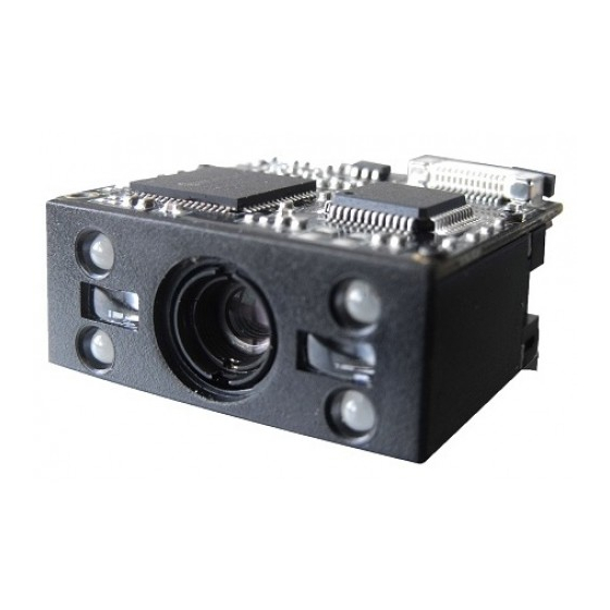
Chapter 1 Introduction Overview NLS-EM3070 series OEM scan engines (hereinafter referred to as “the EM3070” or “the engine”), armed with the Newland patented , a computerized image recognition system, bring about a new era of 2D barcode scan engines. The EM3070’s decoder chip ingeniously blends technology and advanced chip design &... -
Page 8: Chapter 2 Installation
Chapter 2 Installation General Requirements ESD protection has been taken into account when designing the EM3070 and the engine is shipped in ESD safe packaging. Always exercise care when handling the engine outside its package. Be sure grounding wrist straps and properly grounded work areas are used. Dust and Dirt The EM3070 must be sufficiently enclosed to prevent dust particles from gathering on the imager and lens. -
Page 9: Installation Orientation
Installation Orientation The following figure illustrates a front view of the EM3070 after installation. Optics Window Placement The window should be positioned properly to let the illumination and aiming beams pass through as much as possible and no reflections back into the engine (reflections can degrade the reading performance). The window should be mounted close to the front of the engine (parallel). -
Page 10: Window Material And Color
Window Material and Color Wavelengths of illumination and aiming beams should be taken into consideration when choosing window material and color, to achieve the possible highest spectral transmission, lowest haze level and homogeneous refractive index. It is suggested to use PMMA or optical glass with spectral transmittance over 90% and haze less than 1%. -
Page 11: Ambient Light
Ambient Light The EM3070 shows better performance with ambient light. However, high-frequency pulsed light can result in performance degradation. Eye Safety The EM3070 has LEDs that create the aiming and illumination beams. These LEDs are bright, but testing has been done to demonstrate that the engine is safe for its intended application under normal usage conditions. -
Page 12: Front View (Unit: Mm)
Front View (unit: mm) Left View (unit: mm) Bottom View (unit: mm) The bottom view shows the mounting screw specification (M2, machine screw with an internal diameter of 2mm). Note that the part of mounting screws into the engine can not exceed 3mm. -
Page 13: Chapter 3 Electrical Specifications
Chapter 3 Electrical Specifications Power Supply Do not power up the EM3070 until it is properly connected. Be sure the power is cut off before connecting a flexible cable to or disconnecting a flexible cable from the host interface connector. This could damage the engine. -
Page 14: Current
Current Ta=25℃,V =3.3V Parameter Average Maximum Unit Standby Low power... -
Page 15: Chapter 4 Interfaces
Chapter 4 Interfaces The following table lists the pin functions of the 12-pin host interface connector. Refer to the “Cable Connection” section in this chapter for the location of Pin 1. PIN# Signal Name Function Power supply Power supply Ground Input TTL-232 receiving Output... -
Page 16: Host Interface Connector
Host Interface Connector The EM3070’s host interface connector is a 12-pin ZIF socket which can be used to connect a host device (e.g., software development board EVK) with a flat flexible cable. The following figures show the location and dimensions of the socket. (unit: mm) -
Page 17: Dimensions Of The Host Interface Connector
Dimensions of the Host Interface Connector... -
Page 18: Flat Flexible Cable
Flat Flexible Cable A 12-pin flat flexible cable can be used to connect the EM3070 to a host device. The cable design must be consistent with the following specifications shown below. Use reinforcement material for the connectors on the cable and reduce cable impedance for reliable connection and stable performance. Cable Connection Be sure the power is cut off before connecting a flexible cable to the host interface connector on the EM3070. -
Page 19: Communication Interfaces
Communication Interfaces The EM3070 can communicate with the host device through either TTL-232 serial port or USB port using one of the following communication modes. TTL-232: This interface is applicable to most system architectures. For those requiring RS-232, a TTL-232 to RS-232 conversion circuit is needed. -
Page 20: Beeper
Beeper The EM3070 provides a pin (BUZ, PIN 9) on the host interface connector that provides a PWM output to an external driver circuit for generating audible feedback to the user to indicate statuses like power up, good read or operation error. The PWM output is not strong enough to drive a beeper, so a beeper driver circuit is needed. -
Page 21: Good Read Led
Good Read LED The EM3070 provides a pin (LED, PIN 10) on the host interface connector that can be used by an external driver circuit to drive an LED to indicate a good read status. When a good read occurs, the signal from the LED pin turns from a low level into alternation of high and low levels and a while later back to a low level. -
Page 22: Chapter 5 Development Tools
Chapter 5 Development Tools The EM3070’s development tools include both software and hardware and can be utilized for engine performance evaluation, application development and engine configuration. The EVK is provided to help users to test and evaluate the EM3070, which contains beeper & beeper driver circuit, LED &... - Page 23 Headquarters Fujian Newland Auto-ID Tech. Co., Ltd. 3F, Building A, No.1, Rujiang West Rd., Mawei, Fuzhou, Fujian, China 350015 TEL: +86 - (0) 591-83979222 FAX: +86 - (0) 591-83979208 E-mail: marketing@nlscan.com WEB:www.nlscan.com Newland Europe BV Rolweg 25, 4104 AV Culemborg, The Netherlands...