Advertisement
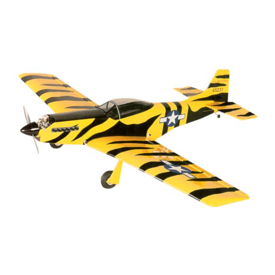
P-51 Mustang
KIT # HRR506
Assembly Instructions
WARRANTY
Herr Engineering Corp. guarantees this kit to be free from defects in both materials and workmanship at the time of
purchase. This warranty does not cover any component damaged buy use or modification. In no case shall Herr
Engineering Corporation's liability exceed the original cost of the purchased kit. Further Herr Engineering Corp.
reserves the right to change or modify this warranty without notice.
In that Herr Engineering Corporation has no control over the assembly or use, no liability shall be assumed or
accepted for any damage resulting from the use by the user during construction of the kit or the use of the final user
assembled product. By the act of building this kit and/or using the final user assembled product, the user accepts all
liability.
If the buyer and/or user is not prepared to accept all of the liability associated with this product, he is advised to
immediately return this kit in new and unused condition to the place of purchase for a full refund.
Herr Engineering Corp.
Award Winning Model Designs
™
A Division of SIG Mfg. Co., Inc.
P.O. Box 520 • Montezuma, Iowa 50171-0520
Phone: (641)623-5154 • Website: www.iflyherr.com
Advertisement
Table of Contents

Summary of Contents for Herr Engineering HRR506
- Page 1 Assembly Instructions WARRANTY Herr Engineering Corp. guarantees this kit to be free from defects in both materials and workmanship at the time of purchase. This warranty does not cover any component damaged buy use or modification. In no case shall Herr Engineering Corporation’s liability exceed the original cost of the purchased kit.
-
Page 2: Kit Contents
Notes about the laser cut parts 1...The first thing that you need to do is to identify and mark the part numbers on the laser cut parts using the drawings on the following pages as a guide. 2...It is possible that several of the laser cut parts may not be completely cut through. If this is the case you can free the part from the sheet quickly using an X-acto knife. - Page 3 Page 3...
- Page 4 Page 4...
-
Page 5: Building Instructions
Additional Items Required ( Not Included in Kit) Note: These are parts that we have used and are familiar with. There are many other brands available and you may substitute other items that you are more comfortable with or have on hand. Qty. - Page 6 12..Pull the aft end of the fuselage together and hold with two cloths pins. 13..Place formers F-9 and F-10 into position and glue to the fuselage sides. 14..Place the fuselage top (F-7) and glue to the fuselage starting at the front and working toward the rear. Glue the aft ends of the fuselage sides together making sure that they are 90 degrees to the top.
- Page 7 44..Place ribs W2 through W-9 into position. Pin the aft ends to the building board and glue the ribs to the lower spar. These ribs should all be 90 degrees to the building board. 45..Place the top spar into position. It should extend past each end of the wing about 1”. Glue the top spar to ribs W-2 through W-9.
-
Page 8: Final Assembly
69..Remove the clothes pins and notch the torque rod block and the trailing edge of the wing to allow the torque rods to move fore and aft. 70..Mark the location of the aileron servo and cut away the top sheet and ribs W-1 to allow the servo to fit into the wing. - Page 9 EVISION Herr Engineering Corp. Kit #506 P-51 Mustang Correction Sheet, Revision #1 1...The grooved hardwood landing gear blocks may be slightly longer than shown on the plan. This is OK. Just center them so an equal amount extends past ribs W-3/W-3A and W-4/W-4A.


Need help?
Do you have a question about the HRR506 and is the answer not in the manual?
Questions and answers