Table of Contents
Advertisement
Quick Links
INSTALLATION & OPERATING
Model :
Serial No :
Manufacturer and Supplier of
Telephone: (07) 3219 2233
Email: sales@ibcwater.com.au
AS0715MP-CL
WATER SOFTENER
WITH MICROPROCESSOR
INSTRUCTIONS
AS0715MP-CL
.............................
FILTRATION & WATER TREATMENT PRODUCTS
for commercial, industrial and residential application
Facsimile: (07) 3219 2266
Website: www.ibcwater.com.au
1
Page
Advertisement
Table of Contents

Related Manuals for IBC Water AS0715MP-CL


Summary of Contents for IBC Water AS0715MP-CL
- Page 1 WATER SOFTENER WITH MICROPROCESSOR INSTALLATION & OPERATING INSTRUCTIONS Model : AS0715MP-CL Serial No : ……………………….. Manufacturer and Supplier of FILTRATION & WATER TREATMENT PRODUCTS for commercial, industrial and residential application Telephone: (07) 3219 2233 Facsimile: (07) 3219 2266 Email: sales@ibcwater.com.au Website: www.ibcwater.com.au...
- Page 2 Maximum Cont. / Peak Drain W x D x H Outlet Flow gram/kg gram/kg Litres Per Kg metres 0.70 AS0715MP-CL 525/1.0 1050/3.6 11 / 15 0.50 BSP-F 1.20 BRINE CHAMBER: POLY MOULDED System Operating Pressure: 330- 690 kPa Temperature: x 43 Electrical: 240V—16VAC 50Hz 3 watts maximum...
- Page 3 AS0715MP-CL Page...
- Page 4 NOTE: The POWER connection transformer socket is on the right hand side as viewed from the front of the valve at the back of the control. Table 3 MODEL RESIN LITRES BRINE TANK - SALT LOADING KG AS0715MP-CL AS0715MP-CL Page...
- Page 5 AS0715MP-CL Page...
- Page 6 WS1-MP VALVE Top Strainer Note Never Shorten the Riser Pipe installed inside the tank. AS0715MP-CL Page...
- Page 7 The final colour is usually blue but with some water a greyish coloured end point is obtained. Using 100ml sample - Hardness ppm = (number tablets x 2) – 1 Contact IBC Water if further details are required. AS0715MP-CL Page...
- Page 8 2.5 , therefore only input a lower figure eg. Calculation gives 58.33 therefore input 57.5. Note :- The chart is based on low to medium total dissolved solids water ,consult IBC Water for using the softener for waters above 250 mg/L hardness.
- Page 9 Press the NEXT button to return to the display screens. If the NEXT button is not pressed hours or minutes will flash for five minutes before returning to display screen. Then using the NEXT button select which screen you wished displayed. Recommended to leave on ‘remaining-M ’. AS0715MP-CL Page...
- Page 10 Note: When changing valve operational cycles the valve control will emit a number of whirring sounds. Note :- The valve cannot be positioned into the regeneration mode without ELECTRIC Power. Note:- It is very important that on commissioning the tank and valve be completely vented of air . AS0715MP-CL Page...
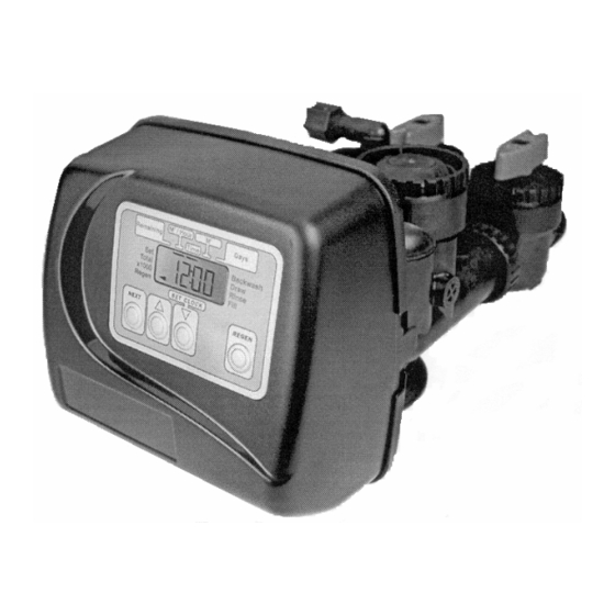
- Page 11 MODEL AS0715MP WATER SOFTENER WITH CONTROL VALVE SERIES MODEL WS1EI AS0715MP-CL Page...
- Page 12 (upflow) 1-20 Regenerate draw/slow rinse (downflow) 1-99 Backwash 2 (upflow) 1-20 or OFF Fast Rinse (downflow) 1-20 or OFF Regenerant Refill (in service with treated water) 0.1 – 99.9 Service (downflow) (Noryl is a trademark of General Electric) AS0715MP-CL Page...
-
Page 13: Table Of Contents
Glossary of Terms …………………………………………………….…. 50 Safety Caution Warning The plug-in transformer for this Never attempt o work on this control while equipment is rated for indoor use standing in or near water without only. disconnecting electrical power to the control. AS0715MP-CL Page... -
Page 14: Introduction
Flow indicator. The display can access the • Display can indicate Rate of Flow actual flow rate through the system. • Four-Digit Display • Throughput and Capacity Setting. Once the • Programming Push Buttons capacity setting is entered, the information cannot AS0715MP-CL Page... - Page 15 Optional second backwash available. • System operation cannot get out of phase or sequence. The control always returns to a fixed conditioned water position after regeneration. • Bypass untreated water is automatically available during regeneration. AS0715MP-CL Page...
- Page 16 Bypass offers simplicity and ease of operation. These softeners are equipped as standard with a bypass valve. See pages 14 and15 Figure 3 – Typical Drain Line Connection – to sewer AS0715MP-CL Page...
- Page 17 Position the softener within 1 ½ metres of a 10 amp GPO. The transformer is connected into the plug socket on the back of the valve control panel. Do not AS0715MP-CL Page...
-
Page 18: Bypass Valve
(i.e. plumbing connection residence. Its completely non-metallic, all plastic somewhere in the building bypasses the system). design allows for easy access and serviceability (Figure 4) without the need for tools. AS0715MP-CL Page... - Page 19 AS0715MP-CL Page...
-
Page 20: Screen Display Information And Programming Instructions
WS1EI Screen Display Information Programming Instructions AS0715MP-CL Page... -
Page 21: General Display Status
Press the arrow until correct minute is displayed. Press the NEXT button to return to the display screens. If the NEXT button is not pressed hours or minutes will flash for five minutes before returning to display screens. AS0715MP-CL Page... - Page 22 General Regeneration Error Screens Status AS0715MP-CL Page...
-
Page 23: Water Conditioner Regeneration
Do not use a fine grade of salt. Have the salt storage tank serviced once a year to remove accumulated sediment that may impede brine draw. Cleaning the Injector/Injector Screen AS0715MP-CL Page... - Page 24 The overflow line must be a direct, separate line from the overflow fitting to the drain, sewer or tube. Allow an air gap as in the drain line connection. Overflow Line Connection AS0715MP-CL Page...
-
Page 25: Placing Softener Into Operation
11. Allow to time out and note water level in brine compartment. The compartment should have been prior filled with salt. The valve will then go back into the service mode. AS0715MP-CL Page... - Page 26 Four methods to initiate regeneration; meter • Printed Circuit (PC) Board. immediate, meter delayed, time clock • Motor delayed or pressure differential. • Drive Gears • Optional double backwash feature offers • Drive Gear Cover optimum regeneration cleaning ability and efficiency. AS0715MP-CL Page...
- Page 27 The exterior of the stack is sealed against the body control, polytube insert and nut assembly. The refill bore with self lubricating EPDM o-rings, while the flow control retainer fits in the refill elbow. The refill AS0715MP-CL Page...
- Page 28 (PC) board. This rotation permits the PC board to record the total volume of treated water and the flow rate. The small centrally located magnet is shielded from water, which substantially reduces iron- fouling problems with the turbine. AS0715MP-CL Page...
- Page 29 SPARE PARTS SERVICING INSTRUCTIONS AS0715MP-CL Page...
- Page 30 V3110 WS1 Drive Gear 12x36 V3109 WS1 Drive Gear Cover V3002EI WS1EI Drive ASY Not Shown V3186-01 WS1 AC ADAPTER CORD ONLY * Drawing number parts 2 through 6 may be purchased as a complete assembly, part V3002EI. AS0715MP-CL Page...
- Page 31 Drive Cap ASY V3178 WS1 Drive Back Plate V3011* WS1 Piston Downflow ASY V3174 WS1 Regenerant Piston V3135 O-ring 228 V3180 O-ring 337 V3105 O-ring 215 (Distributor Tube) Not Shown V3001 WS1 Body ASY Downflow *V3011 is labelled with DN. AS0715MP-CL Page...
- Page 32 WS1 INJECTOR ASSY - YELLOW V3010-1H WS1 INJECTOR ASSY - GREEN V3010-1I WS1 INJECTOR ASSY - ORANGE V3010-1J WS1 INJECTOR ASSY - LIGHT BLUE V3010-1K WS1 INJECTOR ASSY - LIGHT GREEN Not Shown V3170 O-ring 011 Not Shown V3171 O-ring 013 AS0715MP-CL Page...
- Page 33 JCP-P-6 Polytube insert 3/8” JCPG-6PBLK Nut 3/8” H4613 Elbow Cap 3/8” V3163 O-ring 019 V3165-01* WS1 RFC Retainer ASY V3182 WSC RFC Not Shown H4650 Elbow ½” with nut and insert Option * Assembly includes V3182 WS1 RFC. AS0715MP-CL Page...
- Page 34 16 lpm V3162-053 WS1 DLFC 5.3 gpm for ¾ 20 lpm V3162-065 WS1 DLFC 6.5 gpm for ¾ 24.7 lpm V3162-075 WS1 DLFC 7.5 gpm for ¾ 28.5 lpm V3162-090 WS1 DLFC 9.0 gpm for ¾ 34.2 lpm AS0715MP-CL Page...
- Page 35 Water Meter and meter Plug Drawing No. Order No. Description Quantity V3151 WS1 Nut 1: QC V3003* WS1 Meter ASY V3118-01 WS1 Turbine ASY V3105 O-ring 215 * Order number V3003 includes V3118-01 WS1 Turbine Assy and V3105 O-ring 215. AS0715MP-CL Page...
- Page 36 Description: WS1 Fitting ¾” & 1” PVC Solvent 90۫ ASY Drawing No. Order No. Description Quantity V3151 WS1 Nut 1” Quick Connect V3150 WS1 Split Ring V3105 O-Ring 215 V3189 WS1 Fitting ¾ & 1 PVC Solvent 90 AS0715MP-CL Page...
- Page 37 V3151 WS1 Nut 1” Quick Connect V3150 WS1 Split Ring V3105 O-ring 215 V3145 WS1 Bypass 1” Rotor V3146 WS1 Bypass Cap V3147 WS1 Bypass Handle V3148 WS1 Bypass Rotor Seal Retainer V3152 O-ring 135 V3155 O-ring 112 AS0715MP-CL Page...
- Page 38 V3156 O-ring 214 Flow Diagrams – Service and Backwash flow diagram…service AS0715MP-CL Page...
- Page 39 Flow Diagram – Downflow AS0715MP-CL Page...
- Page 40 Flow Diagrams – Rinse and Fill AS0715MP-CL Page...
- Page 41 WS1 Wrench (Order No. V3193-01) AS0715MP-CL Page...
-
Page 42: Service Instructions
Although no tools are necessary to assemble or disassemble the valve, the WS1 wrench (shown in various positions on the valve) may be purchased to aid in assembly or disassembly. Service Instructions AS0715MP-CL Page... - Page 43 Gently turn the motor while inserting so that the gear on the motor meshes with the gears under the drive gear cover. Release the spring clip loop and continue to rotate the motor until the wires are horizontal and the motor housing engages the small plastic bulge inside the drive AS0715MP-CL Page...
- Page 44 The regenerant piston (the small diameter one behind the main piston) is removed from the main piston by pressing sideways and unsnapping it from its latch. Chemically clean in vinegar, or replace the regenerant piston if needed. To remove the main downflow or upflow piston fully extend the piston rod and then unsnap AS0715MP-CL Page...
- Page 45 Push the injector firmly in place, replace the screen and hand tighten the injector cap. Two holes are label “DN” and “UP”. Check for compliance. See Compliance table AS0715MP-CL Page...
- Page 46 A silicone lubricant may be used on the black o-ring. Snap the turbine on the shaft and reinsert the water meter into the side slot. Hand tighten the nut. Do not use a pipe wrench to tighten nut. AS0715MP-CL Page...
- Page 47 (black wire) at the circuit board and plug back in. This resets the electronics and establishes the service piston position. The display should flash all wording, then flash the software version and then reset the valve to the service position. AS0715MP-CL Page...
- Page 48 WS1 WASHER ID 0.257 OD 0.640 Slip the washer and retaining ring on to the end of the piston rod. Attach the microswitch to the drive bracket using the screws. Attach the connector to the microswitch. Attach the terminals to wires and connect. AS0715MP-CL Page...
- Page 49 INJECTOR PERFORMANCE CURVES AS0715MP-CL Page...
- Page 50 AS0715MP-CL Page...
-
Page 51: Troubleshooting
Fuse blown, circuit breaker open, or b. Correct the electrical problem. circuit switched off. 4. Control does not a. Transformer unplugged. a. Plug transformer into outlet; plug trans- regenerate former cable into control. AS0715MP-CL Page automatically. b. Defective control. b. Contact dealer. - Page 52 AS0715MP-CL Page...
- Page 53 Contact dealer. excessively low or high b. Foreign matter affecting controller b. Remove backwash controller. Clean & rate. operation. ! replace. 11. Flowing or dripping water a. Internal valve malfunction. a. Contact dealer. at drain line after regeneration. AS0715MP-CL Page...
- Page 54 Restricted/stalled meter turbine c. Remove meter and check for rotation or foreign matter d. Defective meter d. Replace meter e. Defective PC board e. Replace PC board f. Set-up error f. Check control valve set-up procedure AS0715MP-CL Page...
-
Page 55: Glossary Of Terms
The supply of synthetic organic exchange material any remaining brine solution out of the resin tank to used in water conditioners. This material is subject the drain. to degradation and will need to be renewed. Resin replacement normally varies between 3 to 7 years. AS0715MP-CL Page...
Need help?
Do you have a question about the AS0715MP-CL and is the answer not in the manual?
Questions and answers