
Subscribe to Our Youtube Channel
Related Manuals for ASROCK NUC-1165G7


Summary of Contents for ASROCK NUC-1165G7
- Page 1 NUC-1165G7 NUC-1135G7 NUC-1115G4 NUC-1185G7E NUC-1145G7E NUC-1115G4E NUC-6305E User Manual Version 1.0 Published January 2021 Copyright©2021 ASRock INC. All rights reserved.
- Page 2 (including damages for loss of profits, loss of business, loss of data, interruption of business and the like), even if ASRock has been advised of the possibility of such damages arising from any defect or error in the documentation or product.
- Page 3 ® The terms HDMI and HDMI High-Definition Multimedia Interface, and the HDMI logo are trademarks or registered trademarks of HDMI Licensing LLC in the United States and other countries. CAUTION: RISK OF EXPLOSION IF BATTERY IS REPLACED BY AN INCORRECT TYPE. DISPOSE OF USED BATTERIES ACCORDING TO THE INSTRUCTIONS.
-
Page 4: Table Of Contents
Contents 1 Introduction ............5 1.1 Package Contents ............5 1.2 Specifications ..............6 1.3 Motherboard Layout ............8 1.4 I/O Panel ................ 9 2 Installation ............10 2.1 Screw Holes ..............10 2.2 Pre-installation Precautions ........... 10 2.3 Installation of Memory Modules (SO-DIMM) ....11 2.4 Expansion Slots ............ -
Page 5: Introduction
In case any modifications of this manual occur, the updated version will be available on ASRock website without further notice. You may find the latest VGA cards and CPU support lists on ASRock website as well. ASRock website http://www.asrock.com If you require technical support related to this motherboard, please visit our website for specific information about the model you are using. -
Page 6: Specifications
Interface Realtek ALC233, High Definition Audio NUC-1185G7E/NUC-1145G7E: ® LAN1: Intel I219LM with 10/100/1000 Mbps ® LAN2: Intel I225LM with 10/100/1000/2500 Mbps Controller/ NUC-1115G4E/NUC-1165G7/NUC-1135G7/ Ethernet Speed NUC-1115G4/NUC-6305E: ® LAN1: Intel I219V with 10/100/1000 Mbps ® LAN2: Intel I225LM with 10/100/1000/2500 Mbps... - Page 7 2 x USB 2.0 (1 x 2.00 pitch header) Internal 1 x COM(RS-232) Connector N/A, support onboard TPM 1 x M.2 (KEY M, 2242/2260/2280) with PCIe Gen4 x4 and SATA3 for SSD Storage *M.2 Key M 2280(Supported by bracket) SATA 1 x SATA3.0 (6.0 Gb/s) Watchdog Output...
-
Page 8: Motherboard Layout
1.3 Motherboard Layout 1 : M.2 Key-M Socket (M2_M1) 2 : M.2 Key-E Socket (M2_E1) 3 : USB2.0 Connector (USB2_7_8) 4 : COM Port Header (RS232) 5 : Clear CMOS Header (CLRCMOS1) 6 : SATA3 Port (SATA3_0) 7 : SIO_AT1 8 : System Panel Header (PANEL1) Back Side : Power Button (PWR_BTN1) -
Page 9: I/O Panel
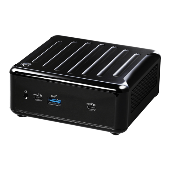
1.4 I/O Panel Front I/O: Rear I/O: USB 3.2 Gen2 Type-C Port (USB3_TC_2) RJ-45 LAN Port (LAN1)** USB 3.2 Gen2 Ports (USB3_1_2) Top : DisplayPort (DP1) USB 3.2 Gen2 Type-C Port (USB3_TC_1) Bottom : HDMI Port (HDMI1) Audio Jack (AUDIO1) USB 3.2 Gen2 Ports (USB3_4_5) RJ-45 LAN Port (LAN2)* DC-In Jack (DC_IN1) -
Page 10: Installation
Chapter 2: Installation Before you install the motherboard, study the configuration of your chassis to ensure that the motherboard fits into it. Make sure to unplug the power cord before installing or removing the motherboard. Failure to do so may cause physical injuries to you and damages to motherboard components. -
Page 11: Installation Of Memory Modules (So-Dimm)
2.3 Installation of Memory Modules (SO-DIMM) This motherboard rovides two 204-pin DDR4 (Double Data Rate 4) SO-DIMM slots. Step 1. Align a SO-DIMM on the slot such that the notch on the SO-DIMM matches the break on the slot. 1. The SO-DIMM only fits in one correct orientation. It will cause permanent damage to the motherboard and the SO-DIMM if you force the SO-DIMM into the slot at incorrect orientation. -
Page 12: Expansion Slots
2.4 Expansion Slots (M.2 Slots) There are 2 M.2 slots on this motherboard. M.2 for SSD: 1 x M.2 (KEY M, 2242/2260/2280) with PCIe Gen4 x4 and SATA3 for SSD. * M.2 Key M 2280(Supported by bracket) M.2 for Wi-Fi: 1 x M.2 (Key E, 2230) with PCIe x1, USB 2.0 and CNVi for Wireless. M.2 Key-M Socket (M2_M1) M.2 Key-E Socket (M2_E1) -
Page 13: Jumpers Setup
2.5 Jumpers Setup The illustration shows how jumpers are setup. When the jumper cap is placed on pins, the jumper is “Short”. If no jumper cap is placed on pins, the jumper is “Open”. The illustration shows a 3-pin jumper whose pin1 and pin2 are “Short”... -
Page 14: Onboard Headers And Connectors
2.6 Onboard Headers and Connectors Onboard headers and connectors are NOT jumpers. Do NOT place jumper caps over these headers and connectors. Placing jumper caps over the headers and connectors will cause permanent damage of the motherboard! SATA3 Connector This Serial ATA3 (SATA3) connector supports SATA data (SATA3_0: see p.8, No. - Page 15 RESET (Reset Switch): Connect to the reset switch on the chassis front panel. Press the reset switch to restart the computer if the computer freezes and fails to perform a normal restart. PLED (System Power LED): Connect to the power status indicator on the chassis front panel. The LED is on when the system is operating.
- Page 16 Back Side: Power Button Header (PWR_BTN1) Fan Connector +12V (FAN1) FAN_SPEED FAN_SPEED_CONTROL Battery Connector (BAT1) ESPI Connector (ESPI1)
-
Page 17: Installation Of Rom Socket
2.7 Installation of ROM Socket * Do not apply force to the actuator cover after ic inserted. * Do not apply force to actuator cover when it is opening over 120 degree, Otherwise, the actuator cover may be broken. * The yellow dot (Pin1) on the ROM must be installed at pin1 position of the socket. -
Page 18: Uefi Setup Utility
Chapter 3: UEFI SETUP UTILITY 3.1 Introduction This section explains how to use the UEFI SETUP UTILITY to configure your system. The UEFI chip on the motherboard stores the UEFI SETUP UTILITY. You may run the UEFI SETUP UTILITY when you start up the computer. Please press <F2>... -
Page 19: Navigation Keys
3.1.2 Navigation Keys Please check the following table for the function description of each navigation key. Navigation Key(s) Function Description Moves cursor left or right to select Screens Moves cursor up or down to select items + / - To change option for the selected items <Enter>... -
Page 20: Advanced Screen
3.3 Advanced Screen In this section, you may set the configurations for the following items: CPU Configu- ration, Chipset Configuration, Storage Configuration, Super IO Configuration, ACPI Configuration, USB Configuration and Trusted Computing. Setting wrong values in this section may cause the system to malfunction. -
Page 21: Cpu Configuration
3.3.1 CPU Configuration Intel Hyper Threading Technology To enable this feature, a computer system with an Intel processor that sup- ports Hyper-Threading technology and an operating system that includes ® ® optimization for this technology, such as Microsoft Windows 10 64-bit / 8.1 ®... - Page 22 Please note that enabling this function may reduce CPU voltage and lead to system stability or compatibility issues with some power supplies. Please set this item to [Disabled] if above issues occur. Intel Turbo Boost Technology Use this item to enable or disable Intel Turbo Boost Mode Technology. Turbo Boost Mode allows processor cores to run faster than marked fre- quency in specific conditions.
-
Page 23: Chipset Configuration
3.3.2 Chipset Configuration VT-d ® ® Use this to enable or disable Intel VT-d technology (Intel Virtualization Technology for Directed I/O). The default value of this feature is [Disabled]. Share Memory Configure the size of memory that is allocated to the integrated graphics processor when the system boots up. -
Page 24: Storage Configuration
3.3.3 Storage Configuration SATA Controller(s) Use this item to enable or disable the SATA Controller feature. SATA Mode Selection Use this to select SATA mode. The default value is [AHCI Mode]. AHCI (Advanced Host Controller Interface) supports NCQ and other new features that will improve SATA disk perfor- mance but IDE mode does not have these advantages. -
Page 25: Super Io Configuration
3.3.4 Super IO Configuration COM1 Configuration Use this to set parameters of COM1. WDT Timeout Reset Use this to set the Watch Dog Timer. -
Page 26: Acpi Configuration
3.3.5 ACPI Configuration Suspend to RAM Use this item to select whether to auto-detect or disable the Suspend-to- RAM feature. Select [Auto] will enable this feature if the OS supports it. Onboard LAN Power On Use this item to enable or disable onboard LAN to turn on the system from the power-soft-off mode. -
Page 27: Usb Configuration
3.3.6 USB Configuration Legacy USB Support Enable or disable Legacy OS Support for USB 2.0 devices. If you encoun- ter USB compatibility issues it is recommended to disable legacy USB support. Select UEFI Setup Only to support USB devices under the UEFI setup and Windows/Linux operating systems only. -
Page 28: Trusted Computing
3.3.7 Trusted Computing Security Device Support Enable or disable BIOS support for security device. -
Page 29: Hardware Health Event Monitoring Screen
3.4 Hardware Health Event Monitoring Screen In this section, it allows you to monitor the status of the hardware on your system, including the parameters of the CPU temperature, motherboard temperature, CPU fan speed, chassis fan speed, and the critical voltage. FAN1 Setting This allows you to set FAN1’s speed. -
Page 30: Security Screen
3.5 Security Screen In this section, you may set, change or clear the supervisor/user password for the system. Supervisor Password Set or change the password for the administrator account. Only the ad- ministrator has authority to change the settings in the UEFI Setup Utility. Leave it blank and press enter to remove the password. -
Page 31: Boot Screen
3.6 Boot Screen In this section, it will display the available devices on your system for you to config- ure the boot settings and the boot priority. Boot From Onboard LAN Use this item to enable or disable the Boot From Onboard LAN feature. Setup Prompt Timeout This shows the number of seconds to wait for setup activation key. -
Page 32: Exit Screen
3.7 Exit Screen Save Changes and Exit When you select this option, it will pop-out the following message, “Save configuration changes and exit setup?” Select [OK] to save the changes and exit the UEFI SETUP UTILITY. Discard Changes and Exit When you select this option, it will pop-out the following message, “Discard changes and exit setup?”... -
Page 33: Software Support
Click on a specific item then follow the installation wizard to install it. 4.2.4 Contact Information If you need to contact ASRock or want to know more about ASRock, you’re welcome to visit ASRock’s website at http://www.asrock.com; or you may con-...
Need help?
Do you have a question about the NUC-1165G7 and is the answer not in the manual?
Questions and answers