Advertisement
Available languages
Available languages
Quick Links
Copyright Notice:
Copyright Notice:
Copyright Notice:
Copyright Notice:
Copyright Notice:
No part of this installation guide may be reproduced, transcribed, transmitted, or trans-
lated in any language, in any form or by any means, except duplication of documen-
tation by the purchaser for backup purpose, without written consent of ASRock Inc.
Products and corporate names appearing in this guide may or may not be registered
trademarks or copyrights of their respective companies, and are used only for identifica-
tion or explanation and to the owners' benefit, without intent to infringe.
Disclaimer:
Disclaimer:
Disclaimer:
Disclaimer:
Disclaimer:
Specifications and information contained in this guide are furnished for informational
use only and subject to change without notice, and should not be constructed as a
commitment by ASRock. ASRock assumes no responsibility for any errors or omissions
that may appear in this guide.
With respect to the contents of this guide, ASRock does not provide warranty of any kind,
either expressed or implied, including but not limited to the implied warranties or
conditions of merchantability or fitness for a particular purpose. In no event shall
ASRock, its directors, officers, employees, or agents be liable for any indirect, special,
incidental, or consequential damages (including damages for loss of profits, loss of
business, loss of data, interruption of business and the like), even if ASRock has been
advised of the possibility of such damages arising from any defect or error in the guide
or product.
This device complies with Part 15 of the FCC Rules. Operation is subject to the
following two conditions:
(1) this device may not cause harmful interference, and
(2) this device must accept any interference received, including interference that
may cause undesired operation.
CALIFORNIA, USA ONLY
The Lithium battery adopted on this motherboard contains Perchlorate, a toxic
substance controlled in Perchlorate Best Management Practices (BMP) regulations
passed by the California Legislature. When you discard the Lithium battery in
California, USA, please follow the related regulations in advance.
"Perchlorate Material-special handling may apply, see
www.dtsc.ca.gov/hazardouswaste/perchlorate"
ASRock Website: http://www.asrock.com
Copyright©2008 ASRock INC. All rights reserved.
Published October 2008
ASRock N7AD-SLI Motherboard
1 1 1 1 1
Advertisement

Subscribe to Our Youtube Channel
Related Manuals for ASROCK N7AD-SLI


Summary of Contents for ASROCK N7AD-SLI
- Page 1 ASRock. ASRock assumes no responsibility for any errors or omissions that may appear in this guide. With respect to the contents of this guide, ASRock does not provide warranty of any kind, either expressed or implied, including but not limited to the implied warranties or conditions of merchantability or fitness for a particular purpose.
-
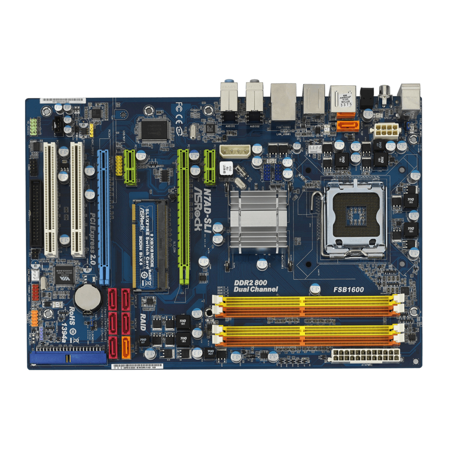
Page 2: Motherboard Layout
775-Pin CPU Socket Infrared Module Header (IR1) NVIDIA nForce 740i SLI Chipset Floppy Connector (FLOPPY1) 2 x 240-pin DDR2 DIMM Slots COM Port Header (COM1) (Dual Channel A: DDRII_1, DDRII_3; Yellow) Front Panel Audio Header 2 x 240-pin DDR2 DIMM Slots (HD_AUDIO1, Lime) (Dual Channel B: DDRII_2, DDRII_4;... - Page 3 Line In (Light Blue) Coaxial SPDIF Out Port Front Speaker (Lime) PS/2 Keyboard Port (Purple) * There are two LED next to the LAN port. Please refer to the table below for the LAN port LED indications. LAN Port LED Indications ACT/LINK...
- Page 4 ASRock’s commitment to quality and endurance. This Quick Installation Guide contains introduction of the motherboard and step-by-step installation guide. More detailed information of the motherboard can be found in the user manual presented in the Support CD.
- Page 5 - 1 x Optical SPDIF Out Port - 6 x Ready-to-Use USB 2.0 Ports - 1 x eSATAII Port - 1 x RJ-45 LAN Port with LED (ACT/LINK LED and SPEED LED) - 1 x IEEE 1394 Port - HD Audio Jack: Side Speaker/Rear Speaker/Central/Bass/...
- Page 6 Connector - 6 x SATAII 3.0Gb/s connectors, support RAID (RAID 0, RAID 1, RAID 0+1, JBOD and RAID 5), NCQ, AHCI and “Hot Plug” functions (see CAUTION 7) - 1 x eSATAII 3.0Gb/s connector (shared with 1 SATAII connector) (see CAUTION 8)
- Page 7 BIOS, applying Untied Overclocking Technology, or using the third-party overclocking tools. Overclocking may affect your system stability, or even cause damage to the components and devices of your system. It should be done at your own risk and expense. We are not responsible for possible damage caused by overclocking.
- Page 8 10. USB/WiFi header can be used to support 2 USB 2.0 ports. It can also be used to support WiFi+AP function with ASRock WiFi-802.11g or WiFi- 802.11n module, an easy-to-use wireless local area network (WLAN) adapter. It allows you to create a wireless environment and enjoy the convenience of wireless network connectivity.
- Page 9 MSI 7300GT-TD256EH * These two cards can only work under Windows ® XP / XP 64-bit OS. For the latest updates of the supported PCI Express VGA card list for SLI Mode, please visit our website for details. ASRock website: http://www.asrock.com/support/index.htm...
-
Page 10: Cpu Installation
Before you insert the 775-LAND CPU into the socket, please check if the CPU surface is unclean or if there is any bent pin on the socket. Do not force to insert the CPU into the socket if above situation is found. - Page 11 775-LAND CPU For proper inserting, please ensure to match the two orientation key notches of the CPU with the two alignment keys of the socket. Step 2-3. Carefully place the CPU into the socket by using a purely vertical motion.
- Page 12 1. It is recommended to use the cap tab to handle and avoid kicking off the PnP cap. 2. This cap must be placed if returning the motherboard for after service. Step 4. Close the socket: Step 4-1. Rotate the load plate onto the IHS.
- Page 13 (the same brand, speed, size and chip-type) DDR2 DIMM pair in the slots of the same color. In other words, you have to install identical DDR2 DIMM pair in Dual Channel A (DDRII_1 and DDRII_3; Yellow slots;...
- Page 14 Unlock a DIMM slot by pressing the retaining clips outward. Step 2. Align a DIMM on the slot such that the notch on the DIMM matches the break on the slot. The DIMM only fits in one correct orientation. It will cause permanent damage to the motherboard and the DIMM if you force the DIMM into the slot at incorrect orientation.
- Page 15 PCI Slots: PCI slots are used to install expansion cards that have the 32-bit PCI interface. PCIE Slots: PCIE1 / PCIE3 (PCIE x1 slot; Green) is used for PCI Express cards with x1 lane width cards, such as Gigabit LAN card, SATA2 card.
- Page 16 1. If you plan to install only one PCI Express VGA card on this motherboard, please install it on PCIE2 slot (Green). In this mode, you do not need to adjust the default setting of ASRock SLI/XFire Switch Card, and please do not remove or lose ASRock SLI/XFire Switch Card when it is still in working condition.
- Page 17 To change it to SLI Mode, you need to reverse the direction of ASRock SLI/XFire Switch Card. Please simultaneously pull open both the retention arms that hold the card in position. The card itself will spring away from the retention slot. Take it out gently by holding its edges, and keep away from touching the connectors (Golden Fingers).
- Page 18 Step 3. Reverse the card direction so as to have the “X8 / X8 MODE” wording side toward the retention slot base. Insert the card into the bottom of the base. Step 4. Push the card down into the retention slot till both the retention arms firmly hold the card into position.
- Page 19 PCIE2 slot. Step 9. Connect a 4-pin ATX power cable to SLI/XFIRE power connector. Step 10. Install the graphics card drivers to your system. After that, you can enable the ® Multi-Graphics Processing Unit (GPU) feature in the NVIDIA nView system tray utility.
- Page 20 E. From the Display Properties dialog box, select the Settings tab then click Advanced. F. Select the NVIDIA GeForce tab. G. Click the slider to display the following screen, then select the SLI multi-GPU item. H. Click the Enable SLI multi-GPU check box.
- Page 21 E. From the pop-up menu, select Set SLI configuration, and then click Apply. * SLI appearing here is a registered trademark of NVIDIA ® Technologies Inc., and is used only for identification or explanation and to the owners’ benefit, without intent to infringe. ASRock N7AD-SLI Motherboard...
-
Page 22: Jumpers Setup
After waiting for 15 seconds, use a jumper cap to short pin2 and pin3 on CLRCMOS1 for 5 seconds. However, please do not clear the CMOS right after you update the BIOS. - Page 23 (33-pin FLOPPY1) (see p.2 No. 23) the red-striped side to Pin1 Note: Make sure the red-striped side of the cable is plugged into Pin1 side of the connector. Primary IDE connector (Blue) (39-pin IDE1, see p.2 No. 16) connect the black end...
- Page 24 2.0 ports. (9-pin USB6_7) (see p.2 No. 36) USB/WiFi Header This header can be used to sup- port 2 USB 2.0 ports. It can also (11-pin USB/WIFI) be used to support WiFi+AP (see p.2 No. 30) function with ASRock WiFi-802.
- Page 25 HDA to function correctly. Please follow the instruction in our manual and chassis manual to install your system. 2. If you use AC’97 audio panel, please install it to the front panel audio header as below: A.
- Page 26 Though this motherboard provides 4-Pin CPU fan (Quiet Fan) support, the 3-Pin CPU fan still can work successfully even without the fan speed control function. If you plan to connect the 3-Pin CPU fan to the CPU fan connector on this motherboard, please connect it to Pin 1-3.
- Page 27 Though this motherboard provides 8-pin ATX 12V power connector, it can still work if you adopt a traditional 4-pin ATX 12V power supply. To use the 4-pin ATX power supply, please plug your power supply along with Pin 1 and Pin 5.
- Page 28 “SATA Operation Mode” option in BIOS setup to RAID mode. If you want to add the eSATAII HDD as a RAID disk, please set “SATA Operation Mode” option in BIOS setup to RAID mode.
- Page 29 SATAII_6 (Port 5) eSATAII_TOP In order to enable the eSATAII port of the I/O shield, you need to connect the orange SATAII connector (SATAII_6 (Port 5); see p.2 No.12) and the eSATAII connector (eSATAII_TOP; see p.2 No.38) with a SATA data cable first.
-
Page 30: Driver Installation Guide
2 . 1 0 Driver Installation Guide To install the drivers to your system, please insert the support CD to your optical drive first. Then, the drivers compatible to your system can be auto-detected and listed on the support CD driver page. Please follow the order from up to bottom side to install those required drivers. -
Page 31: Installing Windows
Untied Overclocking function, please enter “Overclock Mode” option of BIOS setup to set the selection from [Auto] to [CPU, PCIE, Async.]. Therefore, CPU FSB is untied during overclocking, but PCI / PCIE buses are in the fixed mode so that FSB can operate under a more stable overclocking environment. - Page 32 To begin using the Support CD, insert the CD into your CD-ROM drive. It will display the Main Menu automatically if “AUTORUN” is enabled in your computer. If the Main Menu does not appear automatically, locate and double-click on the file “ASSETUP.EXE”...
- Page 33 1. Einführung 1. Einführung 1. Einführung Wir danken Ihnen für den Kauf des ASRock N7AD-SLI Motherboard, ein zuverlässiges Produkt, welches unter den ständigen, strengen Qualitätskontrollen von ASRock gefertigt wurde. Es bietet Ihnen exzellente Leistung und robustes Design, gemäß der Verpflichtung von ASRock zu Qualität und Halbarkeit.
- Page 34 - 1 x Coaxial SPDIF Out port - 1 x Optical SPDIF Out port - 6 x Standard-USB 2.0-Anschlüsse - 1 x eSATAII Port - 1 x RJ-45 LAN Port mit LED (ACT/LINK LED und SPEED LED) - 1 x IEEE 1394 Port ASRock N7AD-SLI Motherboard...
- Page 35 Anschlüsse - 6 x SATAII-Anschlüsse, unterstützt bis 3.0 Gb/s Datenübertragungsrate, unterstützt RAID (RAID 0, RAID 1, RAID 0+1, JBOD und RAID 5), NCQ, AHCI und “Hot Plug” Funktionen (siehe VORSICHT 7) - 1 x eSATAII 3.0 GB/s-Anschlüsse (mit 1 SATAII-Anschlüssen geteilt) (siehe VORSICHT 8) - 1 x ATA133 IDE-Anschlüsse (Unterstützt bis 2 IDE-Geräte)
- Page 36 Beachten Sie bitte, dass Overclocking, einschließlich der Einstellung im BIOS, Anwenden der Untied Overclocking-Technologie oder Verwenden von Overclocking-Werkzeugen von Dritten, mit einem gewissen Risiko behaftet ist. Overclocking kann sich nachteilig auf die Stabilität Ihres Systems auswirken oder sogar Komponenten und Geräte Ihres Systems beschädigen.
- Page 37 Kanal-, 4-Kanal-, 6-Kanal- und 8-Kanal-Modi. Stellen Sie die richtige Verbindung anhand der Tabelle auf Seite 3 her. Bevor Sie eine SATA II Festplatte mit dem SATA II Anschluss verbinden, lesen Sie bitte die “Anleitung zur SATA II Festplatteneinrichtung“ auf Seite 37, um Ihre SATA II Festplatte in den SATA II Modus umzuschalten.
- Page 38 Bevor Sie die 775-Pin CPU in den Sockel sitzen, prüfen Sie bitte, ob die CPU-Oberfläche sauber ist und keine der Kontakte verbogen sind. Setzen Sie die CPU nicht mit Gewalt in den Sockel, dies kann die CPU schwer beschädigen. ASRock N7AD-SLI Motherboard...
- Page 39 Pin1 Orientierungskerbe Orientierungskerbe 775-Pin Sockel 775-Pin CPU Um die CPU ordnungsgemäß einsetzen zu können, richten Sie die zwei Orientierungskerben der CPU mit den beiden Markierungen des Sockels aus. Schritt 2-3. Drücken Sie die CPU vorsichtig in vertikaler Richtung in den Sockel.
- Page 40 Kappe drücken, um ein Entfernen zu erleichtern. 1. Verwenden Sie beim Entfernen die Kappenlasche und vermeiden Sie ein Abreißen der PnP-Kappe. 2. Diese Kappe muss angebracht werden, falls Sie das Motherboard zur Reparatur bringen. Schritt 4. Sockel schließen: Schritt 4-1. Drehen Sie die Ladeplatte auf den Kühlkörper (IHS).
- Page 41 Installation des CPU-Lüfters und Kühlkörpers Für Installationshinweise, siehe Betriebsanleitung Ihres CPU-Lüfters und Kühlkörpers. Unten stehend ein Beispiel zur Installation eines Kühlkörpers für den 775-Pin CPU. Schritt 1. Geben Sie Wärmeleitmaterial auf die Mitte (Tragen Sie Wärmeleitmaterial auf. ) des IHS, auf die Sockeloberfläche.
- Page 42 Chiptyp) DDR2 DIMM-Paare in den Steckplätzen gleicher Farbe installieren. Mit anderen Worten, sie müssen ein identisches DDR2 DIMM-Paar im Dual-Kanal A (DDRII_1 und DDRII_3; gelbe Steckplätze, siehe Seite 2 Nr. 6) oder ein identisches DDR2 DIMM-Paar im Dual-Kanal B (DDRII_2 und DDRII_4; orange Steckplätze, siehe Seite 2 Nr.
- Page 43 Öffnen Sie einen DIMM-Slot, indem Sie die seitlichen Clips nach außen drücken. Schritt 2: Richten Sie das DIMM-Modul so über dem Slot aus, dass das Modul mit der Kerbe in den Slot passt. Die DIMM-Module passen nur richtig herum eingelegt in die Steckplätze.
- Page 44 PCI-Slots: PCI-Slots werden zur Installation von Erweiterungskarten mit dem 32bit PCI-Interface genutzt. PCI Express-Slots: PCIE1 / PCIE3 (PCIE x1-Steckplatz; grün) wird für PCI Express- Karten mit x1 Lane-Breite-Karten verwendet, z.B. Gigabit LAN- Karte, SATA2-Karte. PCIE2 (PCIE x16-Steckplatz; grün) wird für PCI Express x16 Lane-Breite-Grafikkarten oder für die Installation von PCI...
- Page 45 Gehäuseschacht (Slot) , den Sie nutzen möchten und behalten die Schraube für den Einbau der Karte. Schritt 3: Richten Sie die Karte über dem Slot aus und drücken Sie sie ohne Gewalt hinein, bis sie den Steckplatz korrekt ausfüllt. Schritt 4: Befestigen Sie die Karte mit der Schraube aus Schritt 2.
- Page 46 +5VSB (Standby) zu setzen (siehe S.2 - No. 1) und die PS/2 oder USB- Weckfunktionen zu aktivieren. Hinweis: Um +5VSB nutzen zu können, muss das Netzteil auf dieser Leitung 2A oder mehr leisten können. CMOS löschen (CLRCMOS1, 3-Pin jumper) (siehe S.2 - Nr. 17)
- Page 47 (33-Pin FLOPPY1) die rotgestreifte Seite auf Stift 1 (siehe S.2, Nr. 23) Hinweis: Achten Sie darauf, dass die rotgestreifte Seite des Kabel mit der Stift 1- Seite des Anschlusses verbunden wird. Primärer IDE-Anschluss (blau) (39-pin IDE1, siehe S.2, Punkt 16)
- Page 48 Dieses eSATAII Verbindungsstück (eSATAII_TOP: siehe S.2 - No. 38) unterstützt SATA Datenkabel für externe SATAII Funktion. Die gegenwärtige eSATAII eSATAII_TOP Schnittstelle erlaubt bis 3.0 Gb/s Datenübertragungsrate. Serial ATA- (SATA-) SJedes Ende des SATA Datenkabel Datenkabels kann an die SATA...
- Page 49 Geräte), wobei jedoch die Bildschirmverdrahtung am Gehäuse HDA unterstützen muss, um richtig zu funktionieren. Beachten Sie bei der Installation im System die Anweisungen in unserem Handbuch und im Gehäusehandbuch. 2. Wenn Sie die AC’97-Audioleiste verwenden, installieren Sie diese wie nachstehend beschrieben an der Front-Audioanschlussleiste: A.
- Page 50 Erweiterte Einstellungen und wählen Sie Chipset-Konfiguration. Setzen Sie die Option Frontleistenkontrolle von [Automatisch] auf [Aktiviert]. F. Rufen Sie das Windows-System auf. Klicken Sie auf das Symbol in der Taskleiste unten rechts, um den Realtek HD Audio-Manager aufzurufen. ® Für Windows XP / XP 64-Bit Betriebssystem: Klicken Sie auf “Audio-E/A”, wählen Sie die “Anschlusseinstellungen”...
- Page 51 Obwohl dieses Motherboard einen 24-pol. ATX-Stromanschluss bietet, kann es auch mit einem modifizierten traditionellen 20-pol. ATX-Netzteil verwendet werden. Um ein 20-pol. ATX-Netzteil zu verwenden, stecken Sie den Stecker mit Pin 1 und Pin 13 ein. Installation eines 20-pol. ATX-Netzteils ATX 12V Anschluss Bitte schließen Sie an diesen...
- Page 52 Ende (A) des (Option) HDMI_SPDIF-Kabels mit dem HDMI_SPDIF-Anschluss am Motherboard. Schließen Sie dann das weiße Ende (B oder C) des HDMI_SPDIF-Kabels an den HDMI_SPDIF-Anschluss der HDMI-VGA-Karte an. A. Schwarzes Ende B. Weißes Ende (zweipolig) C. Weißes Ende (dreipolig) ASRock N7AD-SLI Motherboard...
- Page 53 Anschließend werden die mit Ihrem System kompatiblen Treiber automatisch erkannt und auf dem Bildschirm angezeigt. Zur Installation der nötigen Treiber gehen Sie bitte der Reihe nach von oben nach unten vor. Nur so können die von Ihnen installierten Treiber richtig arbeiten.
- Page 54 64-Bit in Ihrem System. ® Legen Sie Windows Vista / Vista 64-Bit optische Disc in das optische Laufwerk ein, um Ihr System zu starten. Folgen Sie anschließend den Anweisungen, um das Windows ® Vista / Vista 64-Bit Betriebssystem auf Ihrem System zu installieren.
- Page 55 Entkoppelte Übertaktungstechnologie Dieses Motherboard unterstützt die Entkoppelte Übertaktungstechnologie, durch die der FSB durch fixierte PCI- / PCIE- Busse beim Übertakten effektiver arbeiten. Bevor Sie die Entkoppelte Übertaktung aktivieren, stellen Sie bitte die Option “Overclock Mode” (Übertaktungsmodus) im BIOS von [Auto] auf [CPU, PCIE, Async.] um.
- Page 56 être trouvées dans le manuel l’utilisateur qui se trouve sur le CD d’assistance. Les spécifications de la carte mère et le BIOS ayant pu être mis à jour, le contenu de ce manuel est sujet à des changements sans notification.
- Page 57 - FSB1600/1333/1066/800/533 MHz - Prise en charge de la technologie Hyper-Threading (voir ATTENTION 1) - Prend en charge la technologie Untied Overclocking (voir ATTENTION 2) - Prise en charge de la technologie EM64T par le CPU Chipsets - NVIDIA ® 740i SLI Mémoire...
- Page 58 - br. 8 connecteur d’alimentation 12V ATX - Connecteur d’alimentation SLI/XFIRE - Connecteurs audio internes - Connecteur audio panneau avant - 2 x En-tête USB 2.0 (prendre en charge 4 ports USB 2.0 supplémentaires) (voir ATTENTION 9) - 1 x Connecteur USB/WiFi (voir ATTENTION 10) BIOS...
- Page 59 64-bit Certifications - FCC, CE, WHQL * Pour de plus amples informations sur les produits, s’il vous plaît visitez notre site web: http://www.asrock.com ATTENTION Il est important que vous réalisiez qu’il y a un certain risque à effectuer l’overclocking, y compris ajuster les réglages du BIOS, appliquer la technologie Untied Overclocking, ou...
- Page 60 Energy Saver. Site Web ASRock : http://www.asrock.com 13. Même si cette carte mère offre un contrôle sans souci, il n’est pas recommandé d’y appliquer un over clocking. Des fréquences de bus CPU autres que celles recommandées risquent de rendre le système instable ou d’endommager le CPU et la carte mère.
- Page 61 A chaque désinstallation de composant, placez-le sur un support antistatique ou dans son sachet d’origine. Lorsque vous placez les vis dans les orifices pour vis pour fixer la carte mère sur le châssis, ne serrez pas trop les vis ! Vous risquez sinon d’endommager la carte mère.
- Page 62 Vue d’ensemble du socket 775 broches Avant d’insérer le processeur 775 broches dans le socket, veuillez vérifier que la surface du processeur est bien propre, et qu’il n’y a aucune broche tordue sur le socket. Si c’est le cas, ne forcez pas pour insérer le processeur dans le socket.
- Page 63 1. Il est recommandé d’utiliser la languette du capuchon ; évitez de faire sortir le capuchon PnP. 2. Ce capuchon doit être mis en place si vous renvoyez la carte mère pour service après vente. Etape 4. Refermez le socle : Etape 4-1.
- Page 64 Répétez l’opération avec les autres attaches. Si vous enfoncez les attaches sans les faire tourner dans le sens des aiguilles d’une montre, le dissipateur thermique ne sera pas fixé sur la carte mère.
- Page 65 DDRII_3; slots jaunes; voir p.2 No. 6) ou une paire de DIMM DDR2 identiques dans le Canal Double B (DDRII_2 et DDRII_4; slots orange; voir p.2 No. 7), de façon à ce que la Technologie de Mémoire à Canal Double puisse être activée. Cette carte vous permet également d’installer quatre modules DIMM DDR2 pour la configuration à...
- Page 66 Installation d’un module DIMM Installation d’un module DIMM Installation d’un module DIMM Ayez bien le soin de débrancher l’alimentation avant d’ajouter ou de retirer des modules DIMM ou les composants du système. Etape 1. Déverrouillez un connecteur DIMM en poussant les taquets de maintien vers l’extérieur.
- Page 67 Slots PCI: Les slots PCI sont utilisés pour installer des cartes d’extension dotées d’une interface PCI 32 bits. Slots PCIE: Le PCIE1 / PCIE3 (slot PCIE x1; vert) sert aux cartes PCI Express avec les cartes de largeur x1 voie, comme la carte Gigabit LAN, la carte SATA2.
- Page 68 1. Si vous comptez installer une seule carte VGA PCI Express sur cette carte mère, veuillez l’installer sur le slot PCIE2 (vert). Dans ce mode, vous n’avez pas besoin d’ajuster le réglage par défaut de la carte switch ASRock SLI/XFire, veuillez ne pas enlever ni desserrer la carte switch ASRock SLI/XFire alors qu’elle est toujours en état de marche.
- Page 69 Toutefois, veuillez ne pas effacer la CMOS tout de suite après avoir mis le BIOS à jour. Si vous avez besoin d’effacer la CMOS lorsque vous avez fini de mettre le BIOS à jour, vous devez d’abord initialiser le système, puis le mettre hors tension avant de procéder à...
- Page 70 (FLOPPY1 br. 33) (voir p.2 No. 23) le côté avec fil rouge côté Broche1 Note: Assurez-vous que le côté avec fil rouge du câble est bien branché sur le côté Broche1 du connecteur. Connecteur IDE primaire (bleu) (IDE1 br. 39, voir p.2 fig. 16)
- Page 71 SATA sur le connecteur (en option) d’alimentation sur chaque unité. connecter au Connectez ensuite l’extrémité connecteur c o n n e c t e r à d’alimentation du blanche du cordon d’alimentation l’unité disque SATA sur le connecteur d’alimentation...
- Page 72 1. L’audio à haute définition (HDA) prend en charge la détection de fiche, mais le fil de panneau sur le châssis doit prendre en charge le HDA pour fonctionner correctement. Veuillez suivre les instructions dans notre manuel et le manuel de châssis afin installer votre système.
- Page 73 (voir p.2 No. 3) ien que cette carte mère offre un support de (Ventilateur silencieux) ventilateur de CPU à 4 broches , le ventilateur de CPU à 3 broches peut bien fonctionner même sans la fonction de commande de vitesse du ventilateur.
- Page 74 ATX 12V, il peut toujours travailler si vous adoptez une approche traditionnelle à 4 broches ATX 12V alimentation. Pour utiliser l’alimentation des 4 broches ATX, branchez votre alimentation avec la broche 1 et la broche 4-Installation d’alimentation à 4 broches ATX 12V Connecteur d’alimentation SLI/XFIRE...
- Page 75 En-tête de port COM Cette en-tête de port COM est utilisée pour prendre en charge (COM1 br.9) un module de port COM. (voir p.2 No. 24) Connecteur HDMI_SPDIF Connecteur HDMI_SPDIF, fournissant une sortie audio (HDMI_SPDIF1 3-pin) SPDIF vers la carte VGA HDMI, (voir p.2 No.
- Page 76 Puis, les pilotes compatibles avec votre système peuvent être détectés automatiquement et sont listés sur la page du pilote du CD. Veuillez suivre l’ordre de haut en bas sur le côté pour installer les pilotes requis. En conséquence, les pilotes que vous installez peuvent fonctionner correctement.
- Page 77 / Vista 64-bits sur votre système. Lorsque vous voyez la page “Où souhaitez-vous installer Windows ?”, veuillez insérer le CD Support d’ ASRock dans votre lecteur optique, et cliquer sur le bouton “Charger le pilote” en bas à gauche ® ®...
- Page 78 “Mode de surcadençage” de la configuration du BIOS pour établir la sélection de [Auto] à [CPU, PCIE, Async.]. Par conséquent, le CPU FSB n’est pas lié durant le surcadençage, mais les bus PCI / PCIE sont en mode fixé de sorte que FSB peut opérer sous un environnement de surcadençage plus stable.
- Page 79 Grazie per aver scelto una scheda madre ASRock N7AD-SLI, una scheda madre affidabile prodotta secondo i severi criteri di qualità ASRock. Le prestazioni eccellenti e il design robusto si conformano all’impegno di ASRock nella ricerca della qualità e della resistenza.
- Page 80 Specifiche 1 . 2 1 . 2 Specifiche Piattaforma - ATX Form Factor: 12.0-in x 8.2-in, 30.5 cm x 20.8 cm - Design condensatore compatto (condensatori a conduttore in polimero di alta qualità realizzati al 100% in Giappone) ® Processore...
- Page 81 / bassi / ingresso linea / cassa frontale / microfono (vedi ATTENZIONE 6) Connettori - 6 x connettori SATAII 3.0Go/s, sopporta RAID (RAID 0, RAID 1, RAID 0+1, JBOD e RAID 5), NCQ, AHCI e “Collegamento a caldo” (vedi ATTENZIONE 7) - 1 x eSATAII 3.0Gb/s connettore (compartecipe con 1 connettore...
- Page 82 * Per ulteriori informazioni, prego visitare il nostro sito internet: http://www.asrock.com AVVISO Si prega di prendere atto che la procedura di overclocking implica dei rischi, come anche la regolazione delle impostazioni del BIOS, l’applicazione della tecnologia Untied Overclocking Technology, oppure l’uso di strumenti di overclocking forniti da terzi. L’overclocking può...
- Page 83 Questa scheda madre supporta l’ingresso stereo e mono per il microfono. Questa scheda madre supporta le modalità 2 canali, 4 canali, 6 canali e 8 canali per l’uscita audio. Controllare la tavola a pagina 3 per eseguire il collegamento appropriato.
- Page 84 3. Tenere i componenti per i bordi e non toccare i ICs. 4. Ogni volta che si disinstalla un componente, appoggiarlo su un tappetino antistatico messo a terra o depositarlo nella borsa data in dotazione con il componente.
- Page 85 Vista del socket 775-Pin Prima da inserire la CPU da 775-Pin nel socket, verificare che la superficie della CPU sia pulita e che non ci siano pin piegati nel socket. Non forzare l’inserimento della CPU nel socket se ci sono pin piegati.
- Page 86 1. Si raccomanda di utilizzare la linguetta del cappuccio per la manipolazione ed evitare di far saltare via il cappuccio PnP. 2. Questo tappo deve essere inserito se se la scheda madre deve essere restituita per l’assistenza. Fase 4. Chiudere la presa: Fase 4-1.
- Page 87 Ripetere la stessa operazione con gli altri fastener. Se si premono i fastener verso il basso, senza ruotarli in senso orario, il dissipatore non viene fissato bene alla scheda madre Fase 5. Collegare il cavo di alimentazione della ventola al connettore ventola della CPU sulla scheda madre.
- Page 88 2.3 Installazione dei moduli di memoria (DIMM) La scheda madre N7AD-SLI fornisce quattro alloggiamenti DIMM DDR2 (Double Data Rate 2) a 240 pin, e supporta la tecnologia Dual Channel Memory. Per la configurazione a due canali, è necessario installare sempre coppie identiche (stessa marca, velocità, dimensioni e tipo di chip) di DIMM DDR2 negli alloggiamenti dello...
- Page 89 Sbloccare lo slot DIMM premendo i fermi che lo trattengono verso l’esterno. Step 2. Allineare una DIMM sullo slot così che il pettine della DIMM combaci con la sua sede sullo slot. La DIMM può essere montata correttamente soltanto con un orientamento.
- Page 90 Slot di espansione (Slot PCI ed Slot PCI Express) Slot di espansione (Slot PCI ed Slot PCI Express) Sulla scheda madre N7AD-SLI c’è 2 slot PCI ed 4 slot PCI Express. Slot PCI: Sono utilizzati per installare schede di espansione con Interfaccia PCI a 32-bit.
- Page 91 Step 2. Rimuovere i ganci sullo slot che si intende utilizzare. Tenere a portata di mano le viti. Step 3. Allineare il connettore della scheda con lo slot e premere con decisione finché...
- Page 92 Azzeramento predefinita CMOS Nota: CLRCMOS1 permette di cancellare i dati presenti nel CMOS. I dati del CMOS comprendono le informazioni di configurazione quali la password di sistema, data, ora, e i parametri di configurazione del sistema. Per cancellare e ripristinare i parametri del sistema, spegnere il computer e togliere il cavo di alimentazione dalla presa di corrente.
- Page 93 (33-pin FLOPPY1) Lato del Pin1 con la striscia rossa (vedi p.2 Nr. 24) Nota: Assicurarsi che il lato del cavo con la striscia rossa sia inserito nel lato Pin1 del connettore. Connettore IDE primario (blu) (39-pin IDE1, vedi p.2 item 16)
- Page 94 Connettori eSATAII Questo connettore di eSATAII (eSATAII_TOP: vedi p.2 Nr. 38) sostiene il cavo di dati SATA per la funzione esterna di SATAII. L’interfaccia corrente di eSATAII eSATAII_TOP permette il tasso di trasferimento di dati fino a 3.0 Gb/s. Cavi dati Serial ATA (SATA) Una o altra estremità...
- Page 95 1. La caratteristica HDA (High Definition Audio) supporta il rilevamento dei connettori, però il pannello dei cavi sul telaio deve supportare la funzione HDA (High Definition Audio) per far sì che questa operi in modo corretto. Attenersi alle istruzioni del nostro manuale e del manuale del telaio per installare il sistema.
- Page 96 Sebbene la presente scheda madre disponga di un supporto per ventola CPU a 4 piedini (ventola silenziosa), la ventola CPU a 3 piedini è in grado di funzionare anche senza la funzione di controllo della velocità della ventola. Se si intende collegare la ventola CPU a 3 piedini al connettore della ventola CPU su questa scheda madre, collegarla ai piedini 1-3.
- Page 97 12V, l‘unita‘ puo‘ ancora essere funzionante se viene utilizzata una fornitura elettrica tradizionale a 4-pin ATX 12V. Per usare tale fornitura elettrica 4-pin ATX 12V, prego collegare la presa elettrica al Pin 1 e Pin 5. Installazione elettrica 4-Pin ATX 12V Connettore alimentazione SLI/XFIRE Non è...
- Page 98 Collegare l’estremità nera (A) del cavo HDMI_SPDIF (opzionale) all’intestazione HDMI_SPDIF sulla scheda madre. Quindi collegare l’estremità bianca (B o C) del cavo HDMI_SPDIF al connettore HDMI_SPDIF della scheda HDMI VGA. A. estremità nera B. estremità bianca (2 pin) C. estremità bianca (3 pin)
- Page 99 Quindi, i driver compatibili con il sistema vengono rilevati automaticamente ed elencati nella pagina del driver del CD in dotazione. Per l’installazione dei driver necessari, procedere in base ad un ordine dall’alto verso il basso. In tal modo, i driver installati funzioneranno correttamente.
- Page 100 “Modalità Overclock” nelle impostazioni del BIOS per impostare la selezione da [Auto] a [CPU, PCIE, Async.]. A questo punto, la CPU FSB è “libera” durante l’overclocking, ma i bus PCI / PCIE sono nella modalità fissata in modo tale che l’FSB posa operare sotto un più stabile ambiente di overclocking.
- Page 101 BIOS; altrimenti, POST continua con i suoi test di routine. Per entrare il BIOS Setup dopo il POST, riavvia il sistema premendo <Ctl> + <Alt> + <Delete>, o premi il tasto di reset sullo chassis del sistema. Per informazioni più dettagliate circa il Setup del BIOS, fare riferimento al Manuale dell’Utente (PDF file) contenuto nel cd di...
- Page 102 ASRock. Esta Guía rápida de instalación contiene una introducción a la placa base y una guía de instalación paso a paso. Puede encontrar una información más detallada sobre la placa base en el manual de usuario incluido en el CD de soporte.
- Page 103 Especificación 1.2 Especificación Especificación Especificación Plataforma - Factor forma ATX: 30,5 cm x 20,8 cm, 12,0” x 8,2” - Todo diseño de Capacitor Sólido (condensadores de polímero conductor de alta calidad 100% fabricados en Japón) ® Procesador - LGA 775 para Intel...
- Page 104 - 6 x conexiones SATAII, admiten una velocidad de transferencia de datos de hasta 3,0Gb/s, soporta RAID (RAID 0, RAID 1, RAID 0+1, JBOD y RAID 5), NCQ, AHCI y “Conexión en caliente” (vea ATENCIÓN 7) - 1 x conectador del eSATAII 3.0Gb/s (compartido con 1 conectador de SATAII) (vea ATENCIÓN 8)
- Page 105 ADVERTENCIA Tenga en cuenta que hay un cierto riesgo implícito en las operaciones de aumento de la velocidad del reloj, incluido el ajuste del BIOS, aplicando la tecnología de aumento de velocidad liberada o utilizando las herramientas de aumento de velocidad de otros fabricantes.
- Page 106 2 canales, 4 canales, 6 canales y 8 canales. Consulte la tabla en la página 3 para una conexión correcta. Antes de instalar el disco duro SATAII en el conector SATAII, por favor lea la “Guía de Configuración de Disco Duro SATAII” en la página 37 para ajustar su unidad de disco duro SATAII al modo SATAII.
- Page 107 4. Ponga cualquier componente deslocalizado sobre la bolsa anti- estástica que viene con la placa madre. 5. Al colocar los tornillos en sus agujeros para fijar la placa madre en el chasis, no los apriete demasiado. Eso podría dañar la placa madre.
- Page 108 Socket de 775 agujas CPU de 775 agujas Para insertarla correctamente, asegúrese de que las dos muescas de orientación de la CPU coinciden con las teclas de alineación del socket. Step 2-3. Coloque con cuidado la CPU en el socket con un movimiento totalmente vertical.
- Page 109 Para una correcta instalación, consulte los manuales de instrucciones del ventilador y el disipador de la CPU. A continuación se ofrece un ejemplo para ilustrar la instalación del disipador para la CPU de 775 agujas. (Aplique el material termal de interfaz) Paso 1.
- Page 110 Repita el proceso con los cierres restantes. Si presiona los cierres sin girarlos en el sentido de las agujas del reloj, el disipador no se podrá fijar a la placa madre. Paso 5. Conecte el cabezal del ventilador con el conector del ventilador de la CPU en la placa madre.
- Page 111 S i q u i e r e i n s t a l a r d o s m ó...
- Page 112 Asegúrese de desconectar la fuente de alimentación antes de añadir o retirar módulos DIMM o componentes del sistema. Paso 1. Empuje los clips blancos de retención por el extremo de cada lado de la ranura de memoria. Paso 2. Encaje la muesca del DIMM hacia la cumbrera de la ranura.
- Page 113 Express) Express) Express) Express) La placa madre N7AD-SLI cuenta con 2 ranuras PCI y 4 ranuras PCI Express. Ranura PCI: Para instalar tarjetas de expansión que tienen 32-bit Interface PCI. Ranura PCI Express: La ranura PCIE1 / PCIE3 (ranura PCIE x1, Verde) se utiliza con tarjetas PCI Express con ancho de banda x1, como las tarjetas Gigabit LAN, SATA2.
- Page 114 Paso 2. Quite la tapa que corresponde a la ranura que desea utilizar. Paso 3. Encaje el conector de la tarjeta a la ranura. Empuje firmemente la tarjeta en la ranura. Paso 4. Asegure la tarjeta con tornillos.
- Page 115 3 para habilitar +5VSB (vea p.2, N. 1) (standby) para PS/2 o USB wake up events. Atención: Para elegir +5VSB, se necesita corriente mas que 2 Amp proveida por la fuente de electricidad. Limpiar CMOS (CLRCMOS1, jumper de 3 pins) (vea p.2, N.
- Page 116 1 Atención: Asegúrese que la banda roja del cable queda situado en el mismo lado que el contacto 1 de la conexión. IDE conector primario (azul) (39-pin IDE1, vea p.2, No. 16)
- Page 117 Conexiones de eSATAII Este conectador del eSATAII (eSATAII_TOP: vea p.2 N. 38) apoya el cable de los datos de SATA para la función externa de SATAII. El interfaz actual del eSATAII_TOP eSATAII permite la tarifa de la transferencia de los datos hasta 3.0 Gb/s.
- Page 118 2. Si utiliza el panel de sonido AC’97, instálelo en la cabecera de sonido del panel frontal de la siguiente manera: A. Conecte Mic_IN (MIC) a MIC2_L.
- Page 119 F. Entre en el sistema Windows. Haga clic en el icono de la barra de tareas situada en la parte inferior derecha para entrar en el Administrador de audio HD Realtek. ® Para Windows XP / XP 64-bit OS: Haga clic en “E/S de audio”, seleccione “Configuración de conectores”...
- Page 120 12V, puede todavía trabajar si usted adopta un fuente tradicional de energía de 4-pin ATX 12V. Para usar el fuente de energía de 4-pin ATX 12V, por favor conecte su fuente de energía junto con Pin 1 y Pin 5.
- Page 121 HDMI_SPDIF en la (Opcional) cabecera HDMI_SPDIF de la placa base. Conecte después el a de 8-pin ATX extremo blanco (B o C) del cable cional de energía HDMI_SPDIF en el conector TX 12V, por favor HDMI_SPDIF de la tarjeta VGA HDMI.
- Page 122 Guía de instalación del controlador Guía de instalación del controlador Para instalar los controladores en el sistema, inserte en primer lugar el CD de soporte en la unidad óptica. A continuación, se detectarán automáticamente los controladores compatibles con el sistema y se mostrarán en la página de controladores de CD compatibles.
- Page 123 64 bits en el equipo. Cuando aparezca la página “Where do you want to install Windows?” (¿Dónde desea instalar Windows?), inserte el CD de soporte de ASRock en la unidad óptica y haga clic en el botón “Load Driver” (Cargar controlador) ®...
- Page 124 [Auto] a [CPU, PCIE, Async.]. Por lo tanto, FSB de CPU no está relacionado durante el forzado de reloj, sino los buses PCI / PCIE están en el modo fijo de manera que FSB puede operar bajo un ambiente de forzado de reloj más estable.
- Page 125 1 4 7 1 4 7 1 4 7 1 4 7 1 4 7 ASRock N7AD-SLI Motherboard...
- Page 126 ® ® ® ® ® ® ® 1 4 8 1 4 8 1 4 8 1 4 8 1 4 8 ASRock N7AD-SLI Motherboard...
- Page 127 1 4 9 1 4 9 1 4 9 1 4 9 1 4 9 ASRock N7AD-SLI Motherboard...
- Page 128 ® “ ” ® ® ® ® ® “ “ ” 1 5 0 1 5 0 1 5 0 1 5 0 1 5 0 ASRock N7AD-SLI Motherboard...
- Page 129 ® 1 5 1 1 5 1 1 5 1 1 5 1 1 5 1 ASRock N7AD-SLI Motherboard...
- Page 130 1 5 2 1 5 2 1 5 2 1 5 2 1 5 2 ASRock N7AD-SLI Motherboard...
- Page 131 Pin1 Pin1 1 5 3 1 5 3 1 5 3 1 5 3 1 5 3 ASRock N7AD-SLI Motherboard...
- Page 132 1 5 4 1 5 4 1 5 4 1 5 4 1 5 4 ASRock N7AD-SLI Motherboard...
- Page 133 DDRII_1 DDRII_2 DDRII_3 DDRII_4 (3)* “ ” 1 5 5 1 5 5 1 5 5 1 5 5 1 5 5 ASRock N7AD-SLI Motherboard...
- Page 134 1 5 6 1 5 6 1 5 6 1 5 6 1 5 6 ASRock N7AD-SLI Motherboard...
- Page 135 1 5 7 1 5 7 1 5 7 1 5 7 1 5 7 ASRock N7AD-SLI Motherboard...
- Page 136 1 5 8 1 5 8 1 5 8 1 5 8 1 5 8 ASRock N7AD-SLI Motherboard...
- Page 137 “ ” “ ” “ ” “ ” 1 5 9 1 5 9 1 5 9 1 5 9 1 5 9 ASRock N7AD-SLI Motherboard...
- Page 138 SATAII_2 SATAII_4 SATAII_6 (Port 1) (Port 3) (Port 5) SATAII_1 SATAII_3 SATAII_5 (Port 0) (Port 2) (Port 4) 1 6 0 1 6 0 1 6 0 1 6 0 1 6 0 ASRock N7AD-SLI Motherboard...
- Page 139 1 6 1 1 6 1 1 6 1 1 6 1 1 6 1 ASRock N7AD-SLI Motherboard...
- Page 140 ® ® ® 1 6 2 1 6 2 1 6 2 1 6 2 1 6 2 ASRock N7AD-SLI Motherboard...
- Page 141 1 6 3 1 6 3 1 6 3 1 6 3 1 6 3 ASRock N7AD-SLI Motherboard...
- Page 142 SLI/XFIRE_POWER1 1 6 4 1 6 4 1 6 4 1 6 4 1 6 4 ASRock N7AD-SLI Motherboard...
- Page 143 ® ® ® ® ® ® ® ® 1 6 5 1 6 5 1 6 5 1 6 5 1 6 5 ASRock N7AD-SLI Motherboard...
- Page 144 ® ® ® ® ® ® ® ® ® ® ® ® ® 1 6 6 1 6 6 1 6 6 1 6 6 1 6 6 ASRock N7AD-SLI Motherboard...
- Page 145 “ ” “ ” “ ” 1 6 7 1 6 7 1 6 7 1 6 7 1 6 7 ASRock N7AD-SLI Motherboard...
- Page 146 1 6 8 1 6 8 1 6 8 1 6 8 1 6 8 ASRock N7AD-SLI Motherboard...
- Page 147 ® ® ® ® ® ® ® 1 6 9 1 6 9 1 6 9 1 6 9 1 6 9 ASRock N7AD-SLI Motherboard...
- Page 148 1 7 0 1 7 0 1 7 0 1 7 0 1 7 0 ASRock N7AD-SLI Motherboard...
- Page 149 ® ® ® “ ” ® ® ® ® ® 1 7 1 1 7 1 1 7 1 1 7 1 1 7 1 ASRock N7AD-SLI Motherboard...
- Page 150 ® ® ® 1 7 2 1 7 2 1 7 2 1 7 2 1 7 2 ASRock N7AD-SLI Motherboard...
- Page 151 1 7 3 1 7 3 1 7 3 1 7 3 1 7 3 ASRock N7AD-SLI Motherboard...
- Page 152 1 7 4 1 7 4 1 7 4 1 7 4 1 7 4 ASRock N7AD-SLI Motherboard...
- Page 153 1 7 5 1 7 5 1 7 5 1 7 5 1 7 5 ASRock N7AD-SLI Motherboard...
- Page 154 1 7 6 1 7 6 1 7 6 1 7 6 1 7 6 ASRock N7AD-SLI Motherboard...
- Page 155 1 7 7 1 7 7 1 7 7 1 7 7 1 7 7 ASRock N7AD-SLI Motherboard...
- Page 156 1 7 8 1 7 8 1 7 8 1 7 8 1 7 8 ASRock N7AD-SLI Motherboard...
- Page 157 1 7 9 1 7 9 1 7 9 1 7 9 1 7 9 ASRock N7AD-SLI Motherboard...
- Page 158 1 8 0 1 8 0 1 8 0 1 8 0 1 8 0 ASRock N7AD-SLI Motherboard...
- Page 159 SATAII_2 SATAII_4 SATAII_6 (Port 1) (Port 3) (Port 5) SATAII_1 SATAII_3 SATAII_5 (Port 0) (Port 2) (Port 4) 1 8 1 1 8 1 1 8 1 1 8 1 1 8 1 ASRock N7AD-SLI Motherboard...
- Page 160 1 8 2 1 8 2 1 8 2 1 8 2 1 8 2 ASRock N7AD-SLI Motherboard...
- Page 161 ® ® ® 1 8 3 1 8 3 1 8 3 1 8 3 1 8 3 ASRock N7AD-SLI Motherboard...
- Page 162 1 8 4 1 8 4 1 8 4 1 8 4 1 8 4 ASRock N7AD-SLI Motherboard...
- Page 163 SLI/XFIRE_POWER1 1 8 5 1 8 5 1 8 5 1 8 5 1 8 5 ASRock N7AD-SLI Motherboard...
- Page 164 ® ® ® ® ® ® ® 1 8 6 1 8 6 1 8 6 1 8 6 1 8 6 ASRock N7AD-SLI Motherboard...
- Page 165 ® ® ® ® ® ® ® ® ® ® ® 1 8 7 1 8 7 1 8 7 1 8 7 1 8 7 ASRock N7AD-SLI Motherboard...
- Page 166 ® ® 1 8 8 1 8 8 1 8 8 1 8 8 1 8 8 ASRock N7AD-SLI Motherboard...
Need help?
Do you have a question about the N7AD-SLI and is the answer not in the manual?
Questions and answers