Advertisement
Quick Links
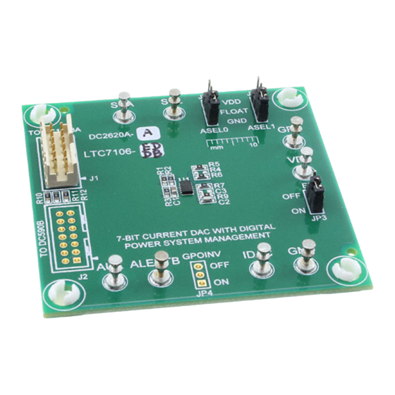
DESCRIPTION
Demonstration circuit 2620A-A uses the LTC7106EDDB,
a precision, bidirectional, 7-Bit current DAC with PMBus
interface and can be used to adjust the output voltage of
any conventional V
referenced regulator. The LTC7106
FB
can work with the vast majority of power management
controllers, regulators or modules to enable digital control
of the output voltage.
The DC2620A-A requires input voltage range from 2.5V
to 5.5V, which can be powered either by external supply
or directly from the DC1613A dongle. The LTC7106 pro-
vides three ranges of IDAC output current: Nominal Range
(–64µA to 63µA), Range High (–256µA to 252µA) and
Range Low (–16µA to 15.75µA). Only the nominal range
is optimized with the highest accuracy. It is recommended
that users design the resistor divider using the nominal
range of the IDAC setting.
PERFORMANCE SUMMARY
SYMBOL
PARAMETER
V
IC Bias Voltage
DD
V
I
Operation Voltage
IDAC
DAC
I
Output Current Range
DAC
A
I
Accuracy
CC
DAC
DEMO MANUAL DC2620A-A
A 7-Bit Current DAC with
To explore the power system management features of the
parts, download the GUI software LTpowerPlay
PC and use ADI's I
to connect to the board. LTpowerPlay allows the user to
reconfigure the part on-the-fly, view IDAC current value
and fault status.
GUI Download
The software can be downloaded from:
http://www.linear.com/LTpowerPlay
For more details and instructions of LTpowerPlay, please
refer to LTpowerPlay for LTC7106 Quick Start Guide.
Design files for this circuit board are available at
http://www.linear.com/demo/DC2620A-A
All registered trademarks and trademarks are the property of their respective owners.
Specifications are at T
A
CONDITIONS
Nominal, LSB = 1µA
Range High, LSB = 4µA
Range Low, LSB = 0.25µA
Nominal Range
LTC7106EDDB
Digital PMBus Interface
2
C/SMBus/PMBus Dongle DC1613A
= 25°C
MIN
TYP
2.5
0.4
–64
–256
–16
–1.5
onto your
®
MAX
UNITS
5.5
V
2.0
V
63
µA
252
µA
15.75
µA
0.8
%
dc2620aaf
1
Advertisement

Subscribe to Our Youtube Channel
Related Manuals for Analog Devices LINEAR DC2620A-A


Summary of Contents for Analog Devices LINEAR DC2620A-A
- Page 1 DEMO MANUAL DC2620A-A LTC7106EDDB A 7-Bit Current DAC with Digital PMBus Interface DESCRIPTION Demonstration circuit 2620A-A uses the LTC7106EDDB, To explore the power system management features of the a precision, bidirectional, 7-Bit current DAC with PMBus parts, download the GUI software LTpowerPlay onto your ®...
- Page 2 DEMO MANUAL DC2620A-A QUICK START PROCEDURE Demonstration circuit 2620A-A makes it easy to use Follow the procedure below: the LTC7106 to adjust any conventional V referenced 1. Make sure JP3 is in OFF position to disable the LTC7106 regulator and evaluate its performances. Refer to Figure 1 before turning on the regulator.
-
Page 3: Quick Start Procedure
DEMO MANUAL DC2620A-A QUICK START PROCEDURE Figure 2 shows an application diagram using the LTC7106 In order to achieve the best IDAC current accuracy of the with a typical DC/DC voltage regulator. By connecting LTC7106, it’s recommended to carefully design the volt- IDAC to the feedback node of the voltage regulator, IDAC age divider so that the LTC7106 uses its nominal range. - Page 4 LTC7106’s DC2620A-A demo system, or a customer LTpowerPlay is a powerful Windows-based develop- board. The software also provides an automatic update ment environment that supports Analog Devices power feature to keep the software current with the latest set system management ICs, including the LTC3880, of device drivers and documentation.
- Page 5 DEMO MANUAL DC2620A-A LTpowerPlay QUICK START PROCEDURE The following procedure describes how to use LTpow- c. In the Toolbar, click the “R” icon (RAM to erPlay to monitor and change the settings of LTC7106. PC) to read the RAM from the LTC7106. This reads the configuration from the RAM of LTC7106 and 1.
- Page 6 DEMO MANUAL DC2620A-A LTpowerPlay QUICK START PROCEDURE In the Telemetry Plot, you will see IDAC current value d. If you want to change the IDAC current to 10μA for change to the commanding value: example, in the Config tab, type “10” in the MFR_ IOUT_COMMAND_LTC7106: Then, click the “W”...
-
Page 7: Parts List
RES., 10k, 1%, 1/10W, 0603 KOA SPEER, RK73H1JTTD1002F R10, R11, R12 RES., 100Ω, 1%, 1/10W, 0603 NIC, NRC06F1000TRF IC, DAC 7-BIT CURRENT DAC ANALOG DEVICES, LTC7106EDDB Additional Demo Board Circuit Components CAP ., OPTION, 0603 OPTION RES., OPTION, 0603 OPTION CONN., OPTION... -
Page 8: Schematic Diagram
DEMO MANUAL DC2620A-A SCHEMATIC DIAGRAM dc2620aaf... - Page 9 Devices for its use, nor for any infringements of patents or other rights of third parties that may result from its use. Specifications subject to change without notice. No license is granted by implication or otherwise under any patent or patent rights of Analog Devices.
- Page 10 Board until you have read and agreed to the Agreement. Your use of the Evaluation Board shall signify your acceptance of the Agreement. This Agreement is made by and between you (“Customer”) and Analog Devices, Inc. (“ADI”), with its principal place of business at One Technology Way, Norwood, MA 02062, USA. Subject to the terms and conditions of the Agreement, ADI hereby grants to Customer a free, limited, personal, temporary, non-exclusive, non-sublicensable, non-transferable license to use the Evaluation Board FOR EVALUATION PURPOSES ONLY.
Need help?
Do you have a question about the LINEAR DC2620A-A and is the answer not in the manual?
Questions and answers