Sign In
Upload
Download
Table of Contents
Contents
Add to my manuals
Delete from my manuals
Share
URL of this page:
HTML Link:
Bookmark this page
Add
Manual will be automatically added to "My Manuals"
Print this page
×
Bookmark added
×
Added to my manuals
Manuals
Brands
Julabo Manuals
Fan
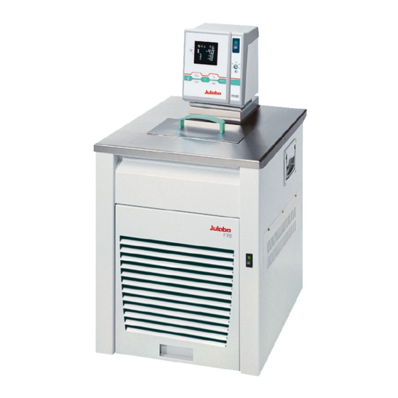
F70-ME
Operating manual
Julabo F70-ME Operating Manual
Ultra-low refrigerated circulators
Hide thumbs
1
2
Table Of Contents
3
4
5
6
7
8
9
10
11
12
13
14
15
16
17
18
19
20
21
22
23
24
25
26
27
28
29
30
31
32
33
34
35
36
37
38
39
40
41
42
43
44
45
46
47
48
49
50
51
52
53
54
55
56
57
58
59
60
61
62
63
64
65
page
of
65
Go
/
65
Contents
Table of Contents
Troubleshooting
Bookmarks
Table of Contents
Table of Contents
Operating Manual
Intended Use
Description
Operator Responsibility - Safety Recommendations
Disposal
Technical Specifications
Operating Instructions
Safety Notes for the User
Explanation of Safety Notes
Explanation of Other Notes
Safety Recommendations
Operating Controls and Functional Elements
Circulator
Cooling Machine
Preparations
Installation
Bath Fluids
Temperature Application to External Systems
Tubing
Filling/Draining
Operating Procedures
Power Connection
Switching on / Start - Stop
Switching on the Circulator
Switching on the Cooling Machine
Setting of Temperatures
Using the Pre-Settings in the Menu
Direct Setting of Temperatures
Safety Installations, Warning Functions
Excess Temperature Protection
Early Warning System, Low Level Protection
Switch-Over from Warning to Shutdown Function
Over and Sub Temperature Warning Function
Menu Functions
Menu Program - Start
MENU PROGRAM - Creation, Administration
MENU PUMP - Setting of Pump Pressure
MENU CONFIG - Configuration of Unit
Remote
Autostart
Off-Mode
Setting of Clock and Date
RESET - Factory Settings
MENU CONTROL - Control Characteristics and Parameters
CONTROL - Control INTERNAL / EXTERNAL
Dynamic Internal
Control Parameters - XPU-, XP-, TN-, TV- EXTERNAL
Control Parameters- XP-, TN-, TV- INTERNAL
Menu Serial - Baudrate, Handshake, Parity
MENU ATC - Absolut Temperature Calibration
Atc Sensor - Internal / External
Atc Status - Yes / no
Calibration Type: 1 -/ 2 -/ 3 Point
Example: 3-Point Calibration for Internal Control
Menu Limits
Limits for Internal Control
Limits for External Control
Troubleshooting Guide / Error Messages
Electrical Connections
Remote Control
Setup for Remote Control
Communication with a PC or a Superordinated Data System
List of Commands
Status Messages
Error Messages
JULABO Service - Online Remote Diagnosis
Cleaning / Repairing the Unit
Warranty Provisions
Advertisement
Quick Links
1
Operating Manual
Download this manual
Operating Manual
ME
Ultra-Low Refrigerated
Circulators
F70-ME
F81-ME
FP89-ME
19530522-V3.doc
JULABO USA, Inc.
884 Marcon Boulevard
Allentown, PA 18109
Phone: +1(610) 231-0250
Fax:
+1(610) 231-0260
info.us@ julabo.com
www.julabo.com
English
15.03.16
Table of
Contents
Previous
Page
Next
Page
1
2
3
4
5
Advertisement
Table of Contents
Need help?
Do you have a question about the F70-ME and is the answer not in the manual?
Ask a question
Questions and answers
Related Manuals for Julabo F70-ME
Fan Julabo FC1200S Operating Manual
Recirculating coolers (45 pages)
Fan Julabo F12-MA Operating Manual
Refrigerated and heating circulators (58 pages)
Fan Julabo F26-ME Operating Manual
Refrigerated and heating circulators (68 pages)
Fan Julabo F81-ME Operating Manual
Ultra-low refrigerated circulators (65 pages)
Fan Julabo FP89-ME Operating Manual
Ultra-low refrigerated circulators (65 pages)
Fan Julabo CF30 Operating Manual
The economy-series, cryo-compact circulators (36 pages)
Fan Julabo CORIO CP-200F Original Operating Manual
Heating immersion circulator, open bath heating circulator, refrigerated circulator (72 pages)
Fan Julabo CF30 Operating Manual
Cryo-compact circulators (38 pages)
This manual is also suitable for:
F81-me
Fp89-me
Table of Contents
Print
Rename the bookmark
Delete bookmark?
Delete from my manuals?
Login
Sign In
OR
Sign in with Facebook
Sign in with Google
Upload manual
Upload from disk
Upload from URL


Need help?
Do you have a question about the F70-ME and is the answer not in the manual?
Questions and answers