Table of Contents
Advertisement
Quick Links
Operating Manual
ME
Refrigerated and
Heating Circulators
F25-ME
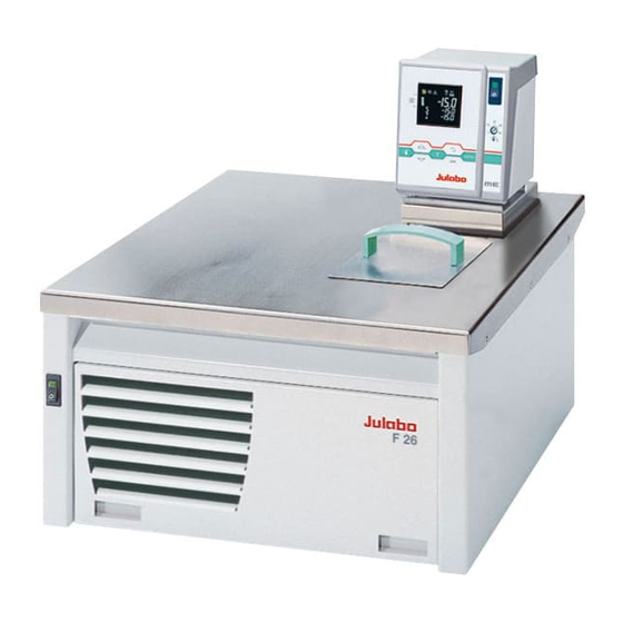
F26-ME
F32-ME
F33-ME
F34-ME
FP40-ME
FP50-ME
water-cooled
FPW50-ME
Translation of the Original Operating Manual
19530512-V1.doc
JULABO USA, Inc.
884 Marcon Boulevard
Allentown, PA 18109
Phone: +1(610) 231-0250
Fax:
+1(610) 231-0260
info.us@ julabo.com
www.julabo.com
English
14.03.16
Advertisement
Table of Contents

Related Manuals for Julabo F26-ME


Summary of Contents for Julabo F26-ME
- Page 1 Operating Manual Refrigerated and Heating Circulators F25-ME F26-ME F32-ME F33-ME F34-ME FP40-ME FP50-ME water-cooled FPW50-ME JULABO USA, Inc. 884 Marcon Boulevard Allentown, PA 18109 Phone: +1(610) 231-0250 Fax: +1(610) 231-0260 Translation of the Original Operating Manual info.us@ julabo.com www.julabo.com 19530512-V1.doc 14.03.16...
- Page 2 Congratulations! You have made an excellent choice. JULABO thanks you for the trust you have placed in us. This operating manual has been designed to help you gain an understanding of the operation and possible applications of our circulators. For optimal utilization of all functions, we recommend that you thoroughly study this manual prior to beginning operation.
-
Page 3: Table Of Contents
TABLE OF CONTENTS Operating manual ......................... 5 Intended use .......................... 5 1.1. Description ........................5 Operator responsibility – Safety recommendations ..............6 2.1. Disposal ..........................8 2.2. Technical specifications ....................9 2.3. Cooling water connection ....................13 Operating instructions .........................14 Safety notes for the user .......................14 3.1. - Page 4 12.2. Communication with a PC or a superordinated data system ..........60 12.3. List of commands ......................61 12.4. Status messages ......................63 12.5. Error messages ........................ 63 13. JULABO Service – Online remote diagnosis ................. 65 14. Cleaning / repairing the unit ....................66 15. WARRANTY PROVISIONS ....................67...
-
Page 5: Operating Manual
Operating manual Intended use JULABO circulators have been designed to control the temperature of specific fluids in a bath tank. The units feature pump connections for temperature control of external systems (loop circuit). JULABO circulators are not suitable for direct temperature control of foods, semi- luxury foods and tobacco, or pharmaceutical and medical products. -
Page 6: Operator Responsibility - Safety Recommendations
Operator responsibility – Safety recommendations Operator responsibility – Safety recommendations The products of JULABO ensure safe operation when installed, operated, and maintained according to common safety regulations. This section explains the potential dangers that may arise when operating the circulator and also specifies the most important safety precautions to preclude these dangers as far as possible. - Page 7 Warning label W26: Colors: yellow, black Hot surface warning. (The label is put on by JULABO) Observe the instructions in the manuals for instruments of a different make that you connect to the circulator, particularly the respective safety recommendations. Also observe the pin assignment of...
-
Page 8: Disposal
Operator responsibility – Safety recommendations 2.1. Disposal The circulator contains a back-up battery that supplies voltage to memory chips when the unit is switched off. Do not dispose of the battery with household waste! Depending on battery regulations in your country, you might be obliged to give back used or defect batteries to gathering places. -
Page 9: Technical Specifications
V/ Hz 115 / 60 Current draw (at 115 V) Mains power connection V/ Hz 100 / 50/60 Current draw (at 100 V) F26-ME F32-ME Working temperature range °C -28 ... 200 -30 ... 200 Temperature stability °C ±0,01 ±0,01 Cooling capacity °C... - Page 10 Operator responsibility – Safety recommendations F33-ME F34-ME Working temperature range °C -30 ... 200 -30 ... 150 Temperature stability °C ±0,01 ±0,01 Cooling capacity °C 0 -20 -30 -20 -30 Medium ethanol 0.5 0.32 0.12 0.03 0.45 0.32 0.14 0.3 Refrigerant R134a R134a...
- Page 11 Temperature selection digital via keypad indication on VFD COMFORT-Display remote control via personal computer indication on monitor Temperature indication VFD COMFORT-DISPLAY Resolution °C 0.01 Absolute Temperature Calibration INT/EXT °C ±3 / ±9 Temperature control PID3 cascade temperatur control Heater wattage (at 230 V) Heater wattage (at 115 V) Electronically adj.
- Page 12 Operator responsibility – Safety recommendations Safety installations according to IEC 61010-2-010: Excess temperature protection adjustable from 0 °C ... 230 °C Low liquid level protection float switch Classification according to DIN 12876-1 class III Supplementary safety installations Early warning system for low level float switch High temperature warning function optical + audible (in intervals)
-
Page 13: Cooling Water Connection
2.3. Cooling water connection Cooling water pressure (IN/OUT) max. 6 bar Pressure difference (IN - OUT) 3.5 to 6 bar Cooling water temperature < 20 °C Notice: Cooling water circuit Risk of oil leaking from the refrigeration system (compressor) of the recirculating cooler into the cooling water in case of a fault in the cooling water circuit! Observe the laws and regulations of the water distribution company valid in the location where the unit is operated. -
Page 14: Operating Instructions
Operating instructions Operating instructions Safety notes for the user 3.1. Explanation of safety notes In addition to the safety warnings listed, warnings are posted throughout the operating manual. These warnings are designated by an exclamation mark inside an equilateral triangle. “Warning of a dangerous situation (Attention! Please follow the documentation).”... -
Page 15: Safety Recommendations
3.3. Safety recommendations Follow the safety instructions to avoid personal injury and property damage. Also, the valid safety instructions for workplaces must be followed. Only connect the unit to a power socket with an earthing contact (PE – protective • earth)! •... - Page 16 Safety notes for the user Caution: The temperature controlling i.e. of fluids in a reactor constitutes normal circulator practice. We do not know which substances are contained within these vessels. Many substances are: • inflammable, easily ignited or explosive • hazardous to health •...
-
Page 17: Operating Controls And Functional Elements
Operating controls and functional elements 4.1. Circulator Front view Rear view Mains power switch, illuminated Navigation keys 1. Key: >OK< Start / Stop (pump / heater ) 2. >OK< in the menu Menu item / select submenu for setting Save set value Save selected parameter A beep signals the end of setting After the actions Start, Stop and change from VFD Display to standard... - Page 18 Four stages, can be set via the key , under >MENU - PUMP<. Adjustable excess temperature protection according to IEC 61010-2-010 Socket: control cable of JULABO refrigerated circulator or output for alarm messages Interface RS232: remote control via personal computer...
-
Page 19: Cooling Machine
Rear view FPW unit Mains power switch, illuminated for cooling machine Socket: control cable of JULABO refrigerated circulator Mains fuses for cooling machine, T10A, D5 x 20 mm Mains power cable with plug for circulator Mains power cable with plug cooling machine... -
Page 20: Preparations
Preparations Preparations 5.1. Installation • Place the unit on an even surface on a pad made of non-flammable material. F34: The circulator fitted with a stainless steel bridge is placed on on the back of the bath tank leaving the bath open on the front side. •... -
Page 21: Temperature Application To External Systems
Fire or other dangers when using bath fluids that are not recommended: Please contact JULABO before using other than recommended bath fluids. Use only nonacidic and noncorrosive bath fluids. JULABO assumes no liability for damage caused by the selection of an unsuitable bath liquid. Unsuitable bath fluids are fluids which, e.g., •... -
Page 22: Tubing
Preparations 5.3.1. Tubing Recommended tubing: Order No. Length Temperature range ® 8 930 008 tubing 8 mm inner dia. -20 °C to 120 °C ® 8 930 010 tubing 10 mm inner dia. -20 °C to 120 °C 8 930 108 Viton tubing 8 mm inner dia. -
Page 23: Filling / Draining
5.4. Filling / draining Notice: • Pay attention to the thermal expansion of bath oil during heating to avoid overflowing of the liquid. Do not drain the bath fluid while it is hot! Check the temperature of the bath fluid prior to draining (by switching the unit on for a short moment, for example). -
Page 24: Operating Procedures
Operating procedures Operating procedures 6.1. Power connection Caution: • Only connect the unit to a power socket with earthing contact (PE – protective earth)! • The power supply plug serves as safe disconnecting device from the line and must be always easily accessible. •... -
Page 25: Switching On The Cooling Machine
Start: • Press key. The actual bath temperature is displayed on the VFD COMFORT- DISPLAY. The circulating pump starts with a slight delay. Stop: • Press key. Keep key pressed. The VFD COMFORT-DISPLAY indicates the message "OFF". 6.2.2. Switching on the Cooling Machine Switching on: •... -
Page 26: Setting Of Temperatures
Setting of temperatures Setting of temperatures 7.1. Using the pre-settings in the menu Press the key to call up the menu for temperature selection. 3 different working temperatures can be adjusted. Their values are freely selectable within the operating temperature range. ... -
Page 27: Direct Setting Of Temperatures
7.2. Direct setting of temperatures The circulator uses the setpoint of SETPNT 1 or 2 or 3 for temperature control The indicated setpoint temperature can be changed directly any time. Example: change 25.00 °C to 50.00 °C 1. By pressing the key the circulator switches to the active SETPOINT<... -
Page 28: Safety Installations, Warning Functions
Safety installations, warning functions Safety installations, warning functions Check the safety installations at least twice a year! Refer to ( page 16) SECVAL Settings for the excess temperature protection > SAFETMP< (Security Values) and for the warning functions for high > OVERTMP< and low > ... -
Page 29: Early Warning System, Low Level Protection
8.1.1. Early warning system, low level protection This low level protection is independent of the control circuit and is divided into two sections: . 1. Switch in stage 1 recognizes a defined fluid level An audible warning sounds (interval tone) and together with the ticker: >... -
Page 30: Switch-Over From Warning To Shutdown Function
Safety installations, warning functions 8.2. Switch-over from warning to shutdown function If a shutdown of functional elements (e.g. heater, circulating pump) is required when the limit values are exceeded or undercut the circulator can be changed over from warning function >WARNING< to shutdown function >ALARM<. -
Page 31: Over And Sub Temperature Warning Function
8.3. Over and Sub temperature warning function If the observance of a working temperature value >SETP< has to be supervised for a sensitive temperature application, then set over and sub Over temperature temperature warning values. In the example below the SETPOINT 85 °C is surrounded by the values OVERTMP 87 °C and SUBTEMP 83 °C. -
Page 32: Menu Functions
Menu functions Menu functions The term „Menu functions“ refers to settings such as Menu level 1 Start program Page 33 Administration and creation of programs Page 35 Electronically adjustable pump capacity Page 37 Configuration of the unit Page 38 REMOTE –... -
Page 33: Menu Program - Start
9.1. MENU PROGRAM – START This menu will start a previously set program. Requirements: 1. Create a program. (refer to next chapter) Start-Menu 2. Return to the Start-MENU and confirm the desired setting of each MENU item with the key 3. - Page 34 Menu functions set the time for the start of the program in the submenu >TIMER<. Submenu TIMER Parameter level >TIME< hours/minutes (hh:mm), set both values one after the other and confirm • hours flash, set by pressing minutes flash, set by pressing >DATE<...
-
Page 35: Menu Program - Creation, Administration
E xxx.xx – external actual value RUN – the program has started or PAUSE – the progress of the program has been interrupted by pressing key. While the time is stopped the temperature will constantly remain at the last calculated setpoint Continue with the key. - Page 36 Menu functions Menu level 1 >EDIT< Create, administer program > STEP< Program step (1 ... 10) >SETPNT < Temperature setpoint of step ... >TSLICE< Duration of step ... > DELETE< delete program step (01 … 10, ALL) Press key, if a parameter is to be retained.
-
Page 37: Menu Pump - Setting Of Pump Pressure
9.3. MENU PUMP – Setting of pump pressure The capacity of the circulating pump is set by adjusting the motor speed Settings: stage / LEVEL 1 ... 4 Display: with illuminated indicator Flow rate: 11 ... 16 l/m Pump pressure: 0,22 ... -
Page 38: Menu Config - Configuration Of Unit
Menu functions 9.4. MENU CONFIG – Configuration of unit Menu level 1 A RESET can be effected only in the >OFF< mode. Switch off circulator by pressing the key and call up the menu CONFIGURATION. Level 2 Parameter level ... -
Page 39: Remote
Take care to fully observe the safety and warning functions of the circulator. Notice: Factory settings: OFF The circulator has been configured and delivered by JULABO in accordance with the NAMUR recommendations. This means for the start mode that the unit must enter a safe operating status after a power failure. -
Page 40: Off-Mode
Menu functions interface. If such a safety standard is not required, the NAMUR recommendations can be bypassed with the AUTOSTART function thus allowing a direct start of the circulator by pressing the mains switch or using a timer. 9.4.3. OFF-MODE Usually the circulating pump is controlled with the key or the Factory setting:... -
Page 41: Menu Control - Control Characteristics And Parameters
9.5. MENU CONTROL – Control characteristics and parameters Menu level 1 The circulator is qualified for internal and external temperature control The switchover is carried out in the menu >C-TYPE< .(INT or EXT). For external temperature control and measurement connect a Pt100 external sensor to the socket at the rear of the circulator. -
Page 42: Control - Control Internal / External
Menu functions Level 2 Parameter level • The parameter flashes, set by pressing 0 … 999 • The parameter flashes, set by pressing 0.1 … 99.9 9.5.1. CONTROL – Control INTERNAL / EXTERNAL Switchover can only be effected if a Pt100 external sensor is connected. -
Page 43: Dynamic Internal
9.5.2. Dynamic internal This parameter affects the temperature sequence only in case of internal control. Factory setting: APER (aperiodic) NORM °C temp. stability Possible parameters: APER NORM Allows for reaching the setpoint faster – with setpoint change or ramp function – but Setpoint overshooting of up to 5 % is possible. -
Page 44: Control Parameters- Xp-, Tn-, Tv- Internal
Menu functions 9.5.4. Control parameters– XP-, TN-, TV- INTERNAL In most cases the control parameters preset in the factory are adequate for achieving an optimum temperature sequence. The control parameters allow adjustment to special control processes.. Proportional range >Xp< The proportional range is the range below the setpoint in which the control circuit reduces the heating capacity from 100% to 0 % Setting range: 0.1 ... -
Page 45: Menu Serial - Baudrate, Handshake, Parity
9.6. MENU SERIAL - BAUDRATE, HANDSHAKE, PARITY Menu level 1 For communication between circulator and a PC or a superordinated process control system the interface parameters of both units must be identical. For remote control refer to page 59 Factory settings: 4800 Baud ... -
Page 46: Menu Atc - Absolut Temperature Calibration
Menu functions 9.7. MENU ATC - Absolut Temperature Calibration ATC serves to compensate a temperature difference that might occur between circulator and a defined measuring point in the bath tank because of physical properties. Principle: For ATC calibration, in steady state the bath temperature at the location Example: of the temperature sensor (CT) is determined at the respective adjusted 1-point calibration... - Page 47 Menu level 1 Level 2 Parameter level Press the key if parameter is to be retained. Correction function for parameters or values (prior to OK). • The parameter flashes, switch by pressing On level 2 a (I) is indicated for internal or an (E) for external.
-
Page 48: Atc Sensor - Internal / External
Menu functions The value is only indicated • Integer digits flash, set by pressing • Decimal digits flash, set by pressing If only a 2-point calibration is carried out, the following menu items are not indicated anymore The value is only indicated ... -
Page 49: Calibration Type: 1 -/ 2 -/ 3 Point
9.7.3. CALIBRATION TYPE: 1 -/ 2 -/ 3 POINT A >1-point<, >2-point< or >3-point< calibration can be carried out. First geometrically define the location for calibration (measuring point CT), then determine the temperature values of the calibration points. The type of calibrations also determines the number of the following pairs of values indicated on the LCD DIALOG-DISPLAY. -
Page 50: Example: 3-Point Calibration For Internal Control
Menu functions 9.7.4. Example: 3-point calibration for internal control In the temperature range from 80 °C to 160 °C the calibration curve of the temperature sensor (TT) is to be adjusted to the actual temperatures at measuring point (CT). 1. Set circulator to internal control: MENU CONTROL page 41 Menu level 1 The type of control can be set only in the –OFF- mode. - Page 51 An ATC calibration is to be carried out. Set to >NO< • The parameter flashes, switch by pressing • The parameter flashes, switch by pressing A >3-point< calibration is carried out. The value >TMPVAL< is only indicated In addition the measured value >CALVAL X< is saved ...
-
Page 52: Menu Limits
Menu functions 9.8. MENU LIMITS Menu level 1 Level 2 Parameter level Press the key if parameter is to be retained. Correction function for parameters or values (prior to OK). • Integer digits flash, set by pressing • Decimal digits flash, set by pressing •... -
Page 53: Limits For Internal Control
9.8.1. Limits for internal control SETPOINT MAX / MIN – Maximum and minimum setpoint Restriction of the adjustable temperature range The limitation of the operating temperature range effects the temperature setting in the menu with the key Only setting of working temperatures which lie within the determined limits is possible Existing settings for SETPNT 1, -2, -3, as well as those for >OVERTMP<... - Page 54 Menu functions BAND HIGH / LOW – Band limitation The band limitation is active during external control. Varied, practice- oriented setting are feasible for heat-up and cool-down phases. Setting range: 0 °C ... 200 °C BAND HIGH and BAND LOW allow for the limitation of the difference between the temperatures in the internal bath and the external system to any maximum value for the heat-up and cool-down phase.
-
Page 55: Troubleshooting Guide / Error Messages
Replace the tubing and refill bath liquid. The float is defect (e.g. transport damage). Repair by authorized JULABO service personnel. Error message with ticker: > REFRIGERATOR ALARM-CHECK CONNECTION < During the self-test after switch-on a short –circuit is detected between pin 2 and pin 4 of the control line or the control line was disconnected during operation. - Page 56 Troubleshooting guide / error messages Error message with ticker: >SENSOR DIFFERENCE ALARM-CHECK VISCOSITY AND PUMP STAGE< Defect of working or excess temperature protector. Working temperature sensor and excess temperature protector report a temperature difference of more than 35 K. Error message with ticker: >...
- Page 57 Press the key for a non-recurring, automatic change of the configuration. In this case please call the JULABO Technical Service or an authorized dealer. Disturbances that are not indicated. The electronic pump motor is overload-protected by an electronic current limiter. If viscosity of the bath fluid is or becomes too high, the motor stops running.
-
Page 58: Electrical Connections
Electrical connections Electrical connections Notice: Use shielded cables only. The shield of the connecting cable is electrically connected to the plug housing. The unit ensures safe operation if connecting cables with a maximum length of 3 m are used. The use of longer cables does not affect proper performance of the unit, however external interferences may have a negative impact on safe operation (e.g. -
Page 59: Remote Control
/ Control output connector may be used for control of JULABO refrigerated circulators or as output for alarm messages. Circuit: Operation = relay powered Alarm = relay not powered Pin assignment: Signal +24 V (I max. current 25 mA) Alarm relay... -
Page 60: Communication With A Pc Or A Superordinated Data System
Remote control 12.2. Communication with a PC or a superordinated data system If the circulator is put into remote control mode via the configuration level, the VFD COMFORT-DISPLAY will read “R -OFF-” = REMOTE STOP. The circulator is now operated via the computer. In general, the computer (master) sends commands to the circulator (slave). -
Page 61: List Of Commands
12.3. List of commands out commands: Setting temperature values or parameters. Command Parameter Response of circulator out_mode_01 Use working temperature > SETPNT 1< out_mode_01 Use working temperature > SETPNT 2< out_mode_01 Use working temperature > SETPNT 3< out_mode_04 Temperature control of internal bath. out_mode_04 External control with Pt100 sensor. - Page 62 Remote control in commands: Asking for parameters or temperature values to be displayed. Command Parameter Response of circulator version none Number of software version (V X.xx) status none Status message, error message (see page 63) in_pv_00 none Actual bath temperature. in_pv_01 none Heating power being used (%).
-
Page 63: Status Messages
Command Parameter Response of circulator in_mode_01 none Selected setpoint: 0 = SETPNT 1 1 = SETPNT 2 2 = SETPNT 3 3 = Last setpoint setting was carried out through an external programmer Internal/external temperature control: in_mode_04 none 0 = Temperature control with internal sensor. 1 = Temperature control with external Pt100 sensor. - Page 64 Remote control Error messages Description -06 SENSOR DIFFERENCE ALARM Sensor difference alarm. Working temperature and safety sensors report a temperature difference of more than 35 K. -07 I C-BUS ERROR Internal error when reading or writing the I C bus. -08 INVALID COMMAND Invalid command.
-
Page 65: Julabo Service - Online Remote Diagnosis
JULABO Service – Online remote diagnosis JULABO circulators of the HighTech series are equipped with a black box. This box is implemented in the controller and records all significant data for the last 30 minutes. In case of a failure, this data can be read out from the unit by using special software. -
Page 66: Cleaning / Repairing The Unit
The circulator is designed for continuous operation under normal conditions. Periodic maintenance is not required. The tank should be filled only with a bath fluid recommended by JULABO. To avoid contamination, it is essential to change the bath fluid from time to time. -
Page 67: Warranty Provisions
WARRANTY PROVISIONS The following Warranty Provisions shall apply to products sold in North America by Julabo (“Seller”) to the entity shown as buyer (“Buyer”) on Seller’s invoice. Initial Warranty. Upon Seller’s receipt of payment in full for the products and subject to Buyer’s... - Page 68 WARRANTY PROVISIONS INCIDENTAL OR CONSEQUENTIAL DAMAGES TO BUYER OR ANY THIRD PARTY AND ALL SUCH DAMAGES ARE HEREBY DISCLAIMED. Assignment. Buyer shall not assign any of its rights or obligations hereunder without the prior written approval of Seller; provided, however, that if Buyer is a distributor of Seller, the rights and obligations of Buyer under these Warranty Provisions shall inure to the benefit of and be binding upon Buyer’s customers who provide the product’s proof of purchase to Seller pursuant to the terms set forth herein.
Need help?
Do you have a question about the F26-ME and is the answer not in the manual?
Questions and answers