Table of Contents
Advertisement
SERVICE
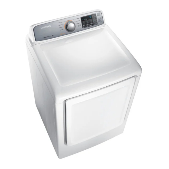
CLOTHES DRYER
CLOTHES DRYER
Basic Model
:
DV400GWHD**
(HUDSON DRYER PROJECT)
Model Name
:
DV45H7000G*
(DV-7000HA DRYER PROJECT)
Model Code
:
DV45H7000GW/A2
Manual
1. Safety Instructions
2. Features and Specifications
3. Disassembly and Reassembly
4. Troubleshooting
5. PBA diagram
6. Wiring diagram
7. Reference information
CONTENTS
Advertisement
Table of Contents


Need help?
Do you have a question about the DV400GWHD Series and is the answer not in the manual?
Questions and answers
Dryer not heating up?