
Related Manuals for HappyJapan HCS3


Summary of Contents for HappyJapan HCS3
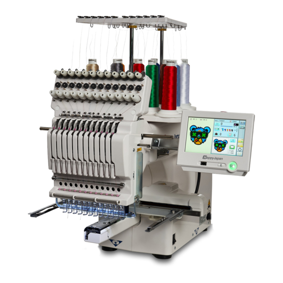
- Page 1 HCS3 Compact Single-head Embroidery Machine INSTRUCTION BOOK Program Ver. *3.00 ~ Original instructions S3V617-2...
-
Page 3: Table Of Contents
INDEX IMPORTANT SAFETY INSTRUCTIONS ... 1-1 SEWING WITH TUBULAR FRAMES WARNING LABELS & THEIR LOCATIONS ..1-2 Installing and removing the frame base .. 6-1 SETTING UP THE MACHINE How to hoop ..........6-2 Remove the machine from box, Putting the hoop on the machine .... 6-3 How to carry machine ...... - Page 4 INDEX SCREEN SAVER ..........21-1 Retrieve built-in data from machine ..11-C i-CUSTOM ..........22-1 Searching pattern data ......11-D LAN connection .........22-2b NEEDLE BAR SELECTION ....12-1 TASK RESERVATION ......22-2c Auto setting ..........12-2 Reading ..........22-2d Thread color ..........12-4 Needle bar selection ......
-
Page 5: Important Safety Instructions
IMPORTANT SAFETY INSTRUCTIONS This electrical appliance is intended for household use. When using an electrical appliance, basic safety precautions should always be followed, includ- ing the following. Read all instructions before using this appliance. DANGER - To reduce the risk of electric shock: 1. -
Page 6: Warning Labels & Their Locations
WARNING LABELS & THEIR LOCATIONS Trapping hazard WARNING Shut the cover when starting the machine. Fear of serious injury. Shut the cover when starting the Do not put hands in while the machine is running. machine. Do not put hands in while the machine is running. -
Page 7: Setting Up The Machine
SETTING UP THE MACHINE We recommend unpacking should be done where it has enough room. CAUTION: To prevent accidents. The machine is quite heavy for one person to carry. Please use two persons when unpacking or carrying. Box (upper) CAUTION: To avoid problems. Make sure to hold bottom of the machine body when removing from the box. -
Page 8: Placement Of Accessories
SETTING UP THE MACHINE Placement of Accessories Confirm all the accessories are contained when unpacking. Frame base USB flash drive (Instruction manual, Parts list, Happy Link Software) Instruction manual Embroidery frame (Round) Embroidery frame (Square) Thread stand Thread guide bracket Carriage Thread stand felt (13 pcs) Power line cord ass’y... -
Page 9: Accessories
SETTING UP THE MACHINE Accessories Please confirm you have received the following. 1. Thread guide bracket 2. Thread guide pillar (2 pcs) 3. Thread stand 4. Thread stand felt (13 pcs) 5. Thread stand pin (13 pcs) 6. Wave washer (13 pcs) 7. -
Page 10: Assemble Machine Unit
SETTING UP THE MACHINE Assemble machine unit 1. Put the thread stand on to the machine and insert the thread guide pillar. (set nut knob nut into the thread guide pillar and 2 washers) Turn the thread guide pillar clockwise with a 3 mm hex- agonal driver until tight. - Page 11 2-4a SETTING UP THE MACHINE 6. Loosen the screw with a offset driver and remove the red shipping collars that are equipped on the both side of the guide bar. (Keep the shipping collars. It is necessary when packing.) 7. Put the carriage and carriage arm together with screw (M4 X 8 2 pcs).
-
Page 12: Assemble Table (Option)
2-4b SETTING UP THE MACHINE Assemble table (Option) Installing theTable. When using the border frame, it is necessary to set the table in advance. 1. Attach the stud (4 places) with the included screws (M6x16). Stud 2. Place the table so that the bed of the ma- chine fi... -
Page 13: Assemble Table Stay And Table (Option)
2-4c SETTING UP THE MACHINE Assemble table stay and table (Option) Installing the table using the table stay. When fi xing the table, use the table stays to place the front of the table on the fl oor. When using the border frame, it is necessary to set the table in advance. 1. - Page 14 2-4d SETTING UP THE MACHINE 3. Place the table so that the bed of the ma- chine fi ts in the recess of the table and push it in the direction of the arrow until it hits the machine. 4. Adjust the stud adjuster so that the bottom Table Needle plate of the needle plate and the top of the table...
-
Page 15: Assemble Border Frame (Option)
2-4e SETTING UP THE MACHINE Assemble border frame (Option) When using the border frame, it is necessary to attach the table in advance. 2-4b, 2-4c 1. Push in the direction of the arrow so that the Carriage Fixing base fixing base of the border frame fi ts under the fixing base of the X carriage. -
Page 16: Machine Installation
SETTING UP THE MACHINE Machine installation 1. Please use a stout table to set the machine Please check for any shaking or excessive vi- brating of the machine table when the machine is running. If you have a problem, Please use a stronger table for the machine. - Page 17 SETTING UP THE MACHINE 4. Please be sure you have this much room around your cap drive for it to move. Please machine on the table positioning like right side drawing. 0 ~ 10 mm 5. Please do not sit the machine near any kind of other electric equipment (Examples: Microwave or electric tool).
- Page 18 SETTING UP THE MACHINE Grounding instruction (for type of 120V) This product must be grounded. In the event of malfunction or breakdown, grounding provides a path of least resistance for electric current to reduce the risk of electric shock. This product is equipped with a cord having an equipment-grounding conductor and a grounding plug.
-
Page 19: Main Parts
MAIN PARTS Hook cover 17. Thread stand 24. Carriage Bobbin case 18. Needle bar selection knob 25. Fuse (6A) 26. Terminal box Hook 19. Control box Needle plate 20. USB port 27. Power switch Thread check spring (Standard-B receptacle) When turning off the machine, be Take-up lever cover 21. - Page 20 MAIN PARTS CONTROL BOX 1. Emergency stop button 6. USB port (Standard-A receptacle) 2. Display (L.C.D.) 7. USB port (Standard-B receptacle) 3. LAN port 8. Stylus 4. Thread cut button 5. Start/Stop button BOBBIN WINDING 1. Upper Thread guide 2. Thread stand pin 3.
-
Page 21: The Control Box
THE CONTROL BOX CAUTION The touch screen can be operated by finger, but in some cases sensitivity of the screen will be affected by condition of the finger. In such cases, please use the fingertip or built-in stylus to hit small touch targets. 1. - Page 22 DRIVE MODE Drive key The each key menu will be shown. Frame forward Needle change i-Custom (default display) Needle bar Pressure foot selection Frame move Drive speed Powe off Turn off the machine. 5-1c Menu Display menu mode. Low speed operation (OFF state) Drive speed Press the button to turn “ON”...
- Page 23 DRIVE MODE Needle change Change Pointer Turn on and off the laser pointer. Laser pointer is located at right side of needle no.1.(Needle no.0 position). When laser pointer is turned on, moving head Change the needle bar directly to the indicated moves to needle no.0 position and radiates.
- Page 24 DRIVE MODE i-Custom 22-1 The following display and key icons are set as default. You can place other frequently used icons freely on the right side of Drive mode screen. When the key is pressed continuously, the “Key Calendar lock” function is activated and the frame will move continuously even the finger is released from the key.
- Page 25 DRIVE MODE Pointer (Option) Quick move Turn on and off the laser pointer. First press this key and then the arrow key to move the frame toward the edge of the max- Position alignment by defining 2 points imum embroidery area in the direction of the arrow.
-
Page 26: Drive Mode
DRIVE MODE Speed setting by needle (ON state) Embroidery speed can be set by needle. If speed by needle exceeds the speed set at Drive speed setting, the value of speed turns gray and speed by the needle is applied to the speed set at Drive speed setting. You can be set up taking the following steps. -
Page 27: Frame Change
3-8a DRIVE MODE Frame change Change the frame according to the pattern to embroider. This helps to confirm positioning between the embroidery area and the pattern. Embroidery area Pattern 1. Press 2. Press 3. Select the type or size of the frame. Tubular round frame Tubular square frame, One touch frame Cap and One-point frame... - Page 28 3-8b DRIVE MODE 4. Press At this time, a warning of A or B may be displayed. When placing the center of the pattern in the Probably the design is larger than the embroidery area of the frame. center of the embroidery area, it may not fit the Confirm the frame size.
- Page 29 DRIVE MODE Display example Needle number and color Mark for color When beginning an embroidery Status Mark for frame out Name of selected pattern Stitches of pattern This indicates that the Memory # of selected pattern machine is ready to start sewing from the “top”...
-
Page 30: Menu
MENU The diagram below describes the layout functions accesed from the main menu. The main menu is accessed by pressing Explanation page Memory pattern Lock of pattern data 11-1 Frame confirmation 13-1 Reading Needle bar selection Erasing Repetition of color group Position alignment by defining Settings Rename... -
Page 31: Inserting A Needle
INSERTING A NEEDLE Select a needle of the right type. See the following “SELECT THREADS”. CAUTION: To prevent accidents. Turn off the power before removing the needle. 1. Loosen the needle clamp screw slightly with the screw- Needle clamp screw driver. -
Page 32: Select Needles And Threads
SELECT NEEDLES AND THREADS About needle Please select needles by type of material . Normally, We supply a DB X K5 needle as in the machine accessory kit. Relation of needle and upper thread Please select type of needle and upper thread by flowing list. k l i Normal em- broidery field... -
Page 33: Backing Materials
BACKING MATERIALS Backing Generally, Backing is used for hooped embroidery fabric. Knit fabrics particularly require the use of embroidery backings. Embroidery backings will allow the hoop to move the fabric more accurately, creating a more beautiful embroidery. Select backing type Choose the thickness and number of sheets by the type of material and embroidery condition. -
Page 34: Bobbin Winding Winding The Bobbin
BOBBIN WINDING Winding the bobbin Thread the bobbin winder as shown below: 1. Upper Thread guide 2. Thread guide 3. Thread tension – Be sure to thread through the small eye before going between the disks. 4. Bobbin (Place the bobbin on the bobbin winder spindle.) 5. -
Page 35: Removing The Bobbin
BOBBIN WINDING CAUTION: To prevent accidents. Please watch out for the point of the rotary hook when you replace the bobbin. Removing the bobbin case 1. Open hook cover (A) to front. 2. With opening the keeper (B) toward front, grasp bobbin case latch (C) and withdraw bobbin case from hook taking care not to damage the thread keeper. -
Page 36: Threading The Machine
THREADING THE MACHINE How to thread upper thread Pass upper threads in order according to the figure: Upper rectifier Thread guide Small cone 1. Thread stand Set thread cone on the stand. Small cones can also be used as shown. Thread 2. - Page 37 THREADING THE MACHINE 4. Minor thread tension 5. Guide pin upper 6. Detecting roller 7. Guide pin lower 8. Thread tension Wind upper threads one time around rotary ten- sion disc clock-wise. 9. Upper thread guide 10. Lower thread guide 11. L ower rectifier 12.
-
Page 38: How To Read These Instructions And Scrollbar
HOW TO READ THESE INSTRUCTIONS and SCROLLBAR How to read these instruction The instructions in this manual have been formatted as follows: Written instructions will be provided on the left side of the page while graphics depicting the nec- essary steps are provided on the right. Graphics on the far right will show the display after performing the steps indicated. -
Page 39: Displaying The Pattern In Setting Mode
DISPLAYING THE PATTERN IN SETTING MODE When there is shows on the right side menu, the pattern data may be shown on the screen. 1. When the machine is stopped, press 2. Select desired menu. Icon of will be shown in sub-menu. 3. -
Page 40: Turning The Machine On How To Turn On The Machine
TURNING THE MACHINE ON How to turn on the machine CAUTION The touch screen can be operated by finger, but in some cases sensitivity of the screen will be affected by condition of the finger. In such cases, please use the fingertip or built-in stylus to hit small touch targets. 1. - Page 41 5-1b TURNING THE MACHINE ON 4. In case you do not need to change frame type, Press After the carriage and frame move slightly, the embroidery frame will return to the previous position automatically. Machine becomes ready for operation. CAUTION: To prevent accidents. The embroidery frame and carriage will move.
-
Page 42: How To Turn Off The Machine
5-1c TURNING THE MACHINE ON How to turn off the machine CAUTION When turning off the machine, be sure to press key on the control box to turn (Power off) off the machine. If the power can not be turned off by pressing this key due to a problem with the machine, turn off the power with the power switch. -
Page 43: Calendar And Clock Setting
TURNING THE MACHINE ON Calendar and clock setting Setting the calendar and clock lets the machine advise when oiling and other maintenance is scheduled to occur. 1. When the machine is stopped, press 2. Press ”OTHER”. 3. Press Current day Current year, month date and time is displayed. -
Page 44: Message
MESSAGES Below is a list of possible messages that may appear while operating the machine, along with an brief explanation and suggested actions to take as a result. The message with mark will be appeared with beep sound. Press the screen (any location is okay), then message will disappear. >>Stop Switch Message CAUTION: To prevent accidents. -
Page 45: Preparation Of Pattern Data Connecting To A Pc
PREPARATION OF PATTERN DATA Connecting to a PC This embroidery machine will allow you to read design data from a connected PC. A USB cable or a LAN cable can be used for the connection. Install the clampfilter In order to avoid unexpected trouble caused by electric noise, install attached clamp filter on the embroidery machine side on USB cable or LAN cable. -
Page 46: Reading Embroidery Pattern Data From The Pc
5-4b PREPARATION OF PATTERN DATA LAN connection Connect the LAN cable between the LAN port of the machine and the network of the PC. Multiple and different type of machines can be connected to a PC which has Happy Link LAN software installed. -
Page 47: Read Embroidery Pattern Data
PREPARATION OF PATTERN DATA Read embroidery pattern data Read the pattern to be embroidered from the memory media. These types of memory media can be used. This machine is able to read FAT or FAT32 format memory media, which are generally used. •USB flash drive If you initialize the memory media with your PC, please proceed with FAT or FAT32 format. -
Page 48: Reading Pattern Data
PREPARATION OF PATTERN DATA Reading pattern data This reads pattern data and writes into memory. When the HAPPY format pattern data with *various function settings are read in memory, vari- ous functions such as needle bar selection, pattern data adjustments and etc. will be set auto- matically. - Page 49 PREPARATION OF PATTERN DATA 5. Select pattern data. --- Reading --- 1 % of free memory is equivalent to about 1,000,000 stitches. --- Check pattern data --- If there are more stitches than remaining space, you may need to delete some designs to make room for the new patterns.
-
Page 50: Search
PREPARATION OF PATTERN DATA Search Search pattern data or folders stored in the selected USB memory (or PC) by name. Search for pattern Cursor 1. Press In this keyboard for searching, all design names are checked beforehand and only candidate alphabets will be highlighted along respective digits. -
Page 51: Selection Of Folders
PREPARATION OF PATTERN DATA Selection of folders The pattern data memory is consist of 20 individual folders. Select desired folder to choose or input pattern data. 1. When the machine is stopped, press Selected folder 2. Select "PATTERN". The pattern data of the selected folder will appear on the display. -
Page 52: How To Select Patterns From Memory
PREPARATION OF PATTERN DATA How to select patterns from memory To select an embroidery design previously stored into the machine memory. 1. When the machine is stopped, press 2. Select “PATTERN”. The display indicates the current pattern. The right side of display shows the number, name and details for the current pattern. -
Page 53: Erasing Patterns From Memory
PREPARATION OF PATTERN DATA Erasing patterns from memory This is to erase an unnecessary design data from the machine memory. Pattern data cannot be erased if the lock is set. 1. When the machine is stopped, press 2. Select “PATTERN”. 3. - Page 54 PREPARATION OF PATTERN DATA Showing number of delete design(s) 5. Press Delete pattern? < 2> Cancel 6. Push "OK" to delete. The item will be deleted. To delete other patterns, repeat steps 3 to 6. Press “Cancel” to cancel the delete. The display will return to step 2.
-
Page 55: Needle Bar Selection
NEEDLE BAR SELECTION For each color change in a given pattern, the needle number loaded with the correct color thread is assigned by the operator. When this is set, the machine automatically changes to the programmed needle when the design reaches that point in the course of sewing the design. You can not setting "NEEDLE"... - Page 56 NEEDLE BAR SELECTION No thread cut mark Frame out mark Color change stop mark Color change stop function When a color change stop is set to a color change number, the machine will stop after it finishes sewing the marked needle number, then following message will be shown: When you wish to start again, Press (Start/Stop button).
-
Page 57: Sewing With Tubular Frames Installing And Removing The Frame Base
SEWING WITH TUBULAR FRAMES Installing and removing the frame base Please attach the frame base to the carriage when you wish to use a tubular embroidering hoop. Please remove it in the reverse order of installation. 1. When the machine is stopped, press 2. - Page 58 6-1b SEWING WITH TUBULAR FRAMES 5. Press button. Knob bolt 6. Move the carriage to the position shown by Carriage press 7. Place the frame base on the carriage guide and tighten the knob bolt on the tubular arm holder completely. Pushing against Move the frame base right or left when it is...
-
Page 59: How To Hoop
SEWING WITH TUBULAR FRAMES How to hoop Inner frame Cloth Backing Outer frame Please stretch the embroidery cloth in the directions of the arrow to smooth the cloth. Tighten Loosen Please smooth the embroidery cloth while adjusting Do not stretch the elastic cloth too much. tightness of outer frame. -
Page 60: Putting The Hoop On The Machine
SEWING WITH TUBULAR FRAMES Putting the hoop on the machine 1. Move the frame base to the approximate center position before inserting the tubular embroidering frame. Frame base Holder Holder 2. Insert the embroidery frame. Make sure that the holder pins are inserted into the positioning holes of the frame base on each side. - Page 61 SEWING WITH TUBULAR FRAMES 6-3b Use TAJIMA made tubular frame You can use TAJIMA made tubular fame which has the same installation width (space be- tween left and right positioning pin) as HAPPY's frame by changing the position of both left and right hold springs and left and right hold spring bases.
-
Page 62: Starting To Embroider
SEWING WITH TUBULAR FRAMES Starting to embroider : Original point 1. Press and move the frame to the (Start point) original point with the 2. Press CAUTION: To prevent accidents. The moving head will move. After the moving head moves to the left end, Please keep hands clear for your safety. -
Page 63: Cap Frame (Option)
CAP FRAME (OPTION) Installing and removing the cap drive frame You need to install the cap drive frame into the carriage when you embroider a cap. Please remove by reverse order of these step. 1. Press and Press The embroidery frame will move to the center . CAUTION: To prevent accidents. - Page 64 CAP FRAME (OPTION) 4. Move the cap drive frame backwards away from you and rotate the rotary cylinder until the rail bracket is upward as shown at right. Mount base Carriage arm 5. Move the cap drive frame in the direction of the arrow, adjust right-and-left mount base to carriage arm and fix them by knob bolts.
- Page 65 CAP FRAME (OPTION) 7. Turn on the power switch. Selected frame is indicated. Selected frame 8. In case required Cap frame is already selected, please jump to operation no.10. In case selected frame type is not same as your requirement, Press 9.
-
Page 66: Normal Cap Frame
CAP FRAME Normal cap frame Adjustment When you hoop a cap on the cap frame, please adjust in the following manner: 1. Adjust up and down position of the hook Wing nut according to the thickness of the cap to adjust clamp tension. - Page 67 CAP FRAME (OPTION) Concave Center guide Hooping caps Locking levers 1. Place cap stretcher securely on a sturdy work bench. 2. As shown in Fig. 5, hold cap frame with both hands and place on cap stretcher. By pushing locking levers at 2 places with fingers, place cap frame so that center guide of cap stretcher fits in concave...
- Page 68 CAP FRAME (OPTION) Center guide Hold lever Cap drive frame Fig. 8 7. Remove the cap frame from the cap stretch- 8. As shown in Fig. 8, place the cap frame on cap the drive frame. You will have to rotate the brim of the hat to the side in order to get past the needle case.
-
Page 69: Wide Cap Frame
CAP FRAME (OPTION) Wide cap frame Tighten Loosen (Thick fabric) (Thin fabric) Adjustment When you fix cap to cap hold frame, please adjust in the following manner. Make sure to do the adjustment of the cap Fig. 1 Hook Cap grip Adjusting hold frame. - Page 70 CAP FRAME (OPTION) Hooping caps Concave Center guide Hold lever 1. Place cap stretcher securely on sturdy work bench. 2. As shown in Fig. 1, hold cap hold frame with both hands and place on cap stretcher. By pushing hold lever at 3 places in arrow marks with fingers, place cap hold frame so that center guide of cap stretcher...
- Page 71 CAP FRAME (OPTION) Clip Lever for clip Clip 6. As shown in Fig. 4, tip the cap stretcher forward. Clip the back of the cap in two places by stretching the crease out as shown by the arrows. Make the clip lever face the inside. Fig.
-
Page 72: Starting To Embroider
CAP FRAME (OPTION) Starting to embroider Embroidery area Embroi- dery area There is a case that the upper part of the cap cannot be embroidered satisfactory depending on shape of a cap. We recommend to change design position or reducing size of the design. - Page 73 CAP FRAME option 4. Press the Embroidery will start. 5. After finishing your design, the display will >>End show ">>End" and the machine will stop. :Original point (Start point) The embroidery frame will return to the original point automatically if the auto origin function has been activated.
-
Page 74: Use Of Y +10Mm Cap Hold Frame
CAP FRAME option Use of Y +10mm cap hold frame 110mm As an option, a cap hold frame that is expanded 10 Extended embroidery area mm in the direction of the peak in the embroidery area can be used. 10mm At this time, the expandable X-direction embroidery Embroidery area area is the central 110 mm. - Page 75 CAP FRAME (OPTION) Changing the needle plate You need to use the needle plate for cap frame when you embroider a cap. When the cap frame is not used, it must be re- turned to the for fl at sewing needle plate, and the height of the pressure foot must be adjust- ed to match the for fl...
- Page 76 CAP FRAME option 7. Press and keep until a fixing screw Fixing screw for pressure foot for pressure foot appears at the position as photo. CAUTION: To prevent accidents. The needle will down. Please keep your hands clear for your safe- 8.
- Page 77 CAP FRAME option 10. Press 11. Press Pressure foot and needle back to standby position automatically. 12. Press to select next Needle. Repeat steps from 6 to 11, then adjust Pressure foot height of all needles. 13. Press Press to return to Drive mode. 7-1b U801...
-
Page 78: Adjusting The Thread Tensions
ADJUSTING THE THREAD TENSIONS 1. With the thread going through the hole of the pressure foot, pull it out slowly toward the front. Pressure foot 2. Adjust the Minor thread tension by the first tension knob and then the second Thread First tension tension knob. According to the type of upper thread and cloth. Second tension Tighten Loos-... -
Page 79: Sewing
SEWING What to do if the thread breaks while sewing If the thread breaks or runs out while sewing, the machine senses the break, stops, and moves back several stitches from the break point. (This prevents open sections in the design when sewing is resumed. See the thread break sec- tion. -
Page 80: Loss Of Power While Embroidering
SEWING Loss of power while embroidering If you have a power failure while embroidering, follow these instructions and you can restore the position of the frame and the pattern data to its state before the failure. 1. Turn on the power switch. 2. -
Page 81: Moving The Hoop While Embroidering And Then Returning To The Correct Location (Position)
SEWING Moving the hoop while embroidering and then returning to the correct location >>Stop Switch 1. Stop the sewing by pressing the while embroidering. 2. Press and move frame with 3. Press The frame will automatically return to the current sewing position. -
Page 82: Going Back To The Beginning Of The Design (Top)
SEWING Going back to the beginning of the design (Top) Stopping sewing in the middle of a design, changing the design’s location in the hoop, and then restarting from the beginning. If you use “Top”, you will return to the start point the frame position left where it is. 1. -
Page 83: Rotating And Mirroring Designs (Convert)
SEWING Rotating and mirroring designs (Convert) Convert selected pattern data. Setting example Normal Mirror reverse : Start point of pattern 0° 90° 180° 270° 0° 90° 180° 270° Mirror reverse + 90° Normal Normal angle With the start point of pattern as a pivot, the machine changes the angle in 90 degree increments. -
Page 84: Starting In The Middle Of A Design (Position)
SEWING Starting in the middle of a design (POSITION) This function allows you to go directly to a stitch number or a color change and positions the hoop correctly. Change (Color position ) Stitch (Number of stitches ) This moves the frame to the beginning of any This moves the frame to any stitch number Color change number. - Page 85 SEWING Change 1. Press ”Frame forward”. Pointer shows you the current position of the frame. 2. Press 3. Input the color change number and press The frame moves to the selected color position. CAUTION: To prevent accidents. The frame moves quickly. Keep hands away from the frame.
-
Page 86: Position Alignment By Defining 2 Points
POSITION ALIGNMENT BY DEFINING 2 POINTS When embroidery position is aligned, machine automatically sets angle and embroidery only by defining 2 points (P1, P2). This function is easy to align the position for embroidery on the edge of pocket or over seam of shirt. - Page 87 POSITION ALIGNMENT BY DEFINING 2 POINTS The procedure is explained as an example of embroidering pattern on pocket of shirt. 1. Hoop a shirt on embroidery frame. (Diagonal position of pocket on frame is okay.) Set the frame on the machine.
- Page 88 POSITION ALIGNMENT BY DEFINING 2 POINTS 7. Press Enter movement of arrow from base line (edge of pocket) to pattern. Enter “15.0”(15mm) in this case. Base line 8. Press Enter movement of arrow from base line (edge of pocket) to pattern. Leave “0.0”...
-
Page 89: Position
POSITION This creates direct designations to the number of stitches and *color change number, as well as setting the frame and data to the designated sewing position. Piece Change Stitch (Color position ) (Number of stitches ) : Beginning of any couloir number : Any stitches : Beginning of any pieces Piece... -
Page 90: Piece Number
POSITION Piece number The frame and pointer can be moved a specified piece number. 1. Press ”Frame forward”. 2. Press 3. Input the number and press The frame and pointer will move to the specified piece number. CAUTION: To prevent accidents. The frame moves quickly. -
Page 91: Bobbin Thread Alarm
9-Ca POSITION / BOBBIN THREAD ALARM Bobbin thread alarm By entering the number of stitches per one bobbin, the machine can be stopped automatically when the remaining amount of bobbin thread becomes low. Also, the alarm message will be displayed on the screen. When the number of stitches is entered, the bobbin thread progress bar will be displayed just below the embroidery progress bar. - Page 92 9-Cb POSITION / BOBBIN THREAD ALARM 3. Press to set the desired number of stitches.. Input the stitich number and press The standard bobbin which is winded with #120 cotton thread will be used around 30000 stitches. But, the consumption of bobbin thread is varied depending on embroidery conditions such as stich type, stitch length and thread tension.
- Page 93 9-Cc POSITION / BOBBIN CHANGE ALERT Condition setting In order for the machine to calculate the number of stitches that can be embroidered with one bobbin, set various conditions such as the size of the bobbin used and the diameter of the bobbin thread being wound.
- Page 94 9-Cd POSITION / BOBBIN CHANGE ALERT 3. Remove the bobbin and check the remaining amount. When the remaining amount is suitable, it is no need to correct the value. Please continue embroidery. The correction of setting value is required when the remaining amount is overage or shortage.
-
Page 95: Work Save
9-Ce POSITION / WORK SAVE Work save You can save the state (before, during) of working design (the design displayed on the drive mode) and the selected frame type for the working design. This allows you to resume work by suspend sewing and returning to the state before the suspend of the driving design even after working other designs. - Page 96 9-Cf POSITION / WORK SAVE Load Loads the saved working design's state and the selected frame type, and restore it to the state before suspend sewing. 1. Press ”Frame forward”. 2. Press "Load” . Saved working design Saved time Selected frame Stitches of pattern Number of stitches sewn up to now...
-
Page 97: Register
REGISTER Register will restore the position of the frame to the last point before a power failure even if the point of origin or the pattern itself were changed. Selected frame If register is used with a cap drive frame, make sure that the machine recognizes it by showing “Cap”... - Page 98 REGISTER Entry This registers the original point of the selected pattern. 1. Press 2. Confirm that there is indication of (Top) in the display and go on to procedure no. 3. Press “Top”, if there is not a indication. Upper right indication of will be shown. 3.
-
Page 99: Return
REGISTER Return In case of power failure you can return to the original point you registered. CAUTION: To prevent accidents. The frame moves quickly. Keep your hands away from the frame. 1. Press 2. Confirm that there is indication of (Top) in the display and go on to procedure no. 3. Press “Top”, if there is not a indication. -
Page 100: Reading Join
10-1 READING Join Joining 2 patterns into 1 pattern data to be read from a memory media. Function of joining patterns is not valid for pattern data in PC connected with LAN. In case you would like to use “Join” function, please set “Join design data” to “YES” on “READING” setting in advance. - Page 101 10-2 READING 5. Select the pattern. --- Reading --- Once design is read. Enable to read other pattern data. 6. Press Disk set O.K.? 7. Press Shift the Memory media if the pattern data you desire to Join is in the other Memory media. 8.
-
Page 102: Pattern Read Settings
READING 10-3 Pattern read settings Settings related to pattern data reading: SETTING ITEM SETTING RANGE (Difult is underlined) 1 Keep null (CHG.) Yes•No : This function lets the machine read zero stitches as they are before color change when reading pattern data. This lets you choose to ignore all null stitches when reading pattern 2 Skip null stitch Yes•No... - Page 103 READING 10-4 8 Design information *Various settings are saved together with a pattern. If some settings are changed in the pattern and you wish to return to the originals, simply reload. The data may only be HAPPY format (TAP). 9 Trace type You can compare the design size and design position to the embroidery frame before you start sewing.
- Page 104 10-5 READING 1. When the machine is stopped, press 2. Select “OPTION”. 3. Select 4. Select desired setting item and change the setting. You can move to next page by pressing Press , all settings are returned to the de- fault.
-
Page 105: Locking Pattern Data
PATTERNS IN MEMORY 11-1 Locking pattern data Locking pattern data stored in the machine memory will prevent deletion and changes in set- tings. 1. When the machine is stopped, press 2. Select "PATTERN". 3. Press from right submenu. 4. Select desired pattern. Mark will appear right of the pattern. - Page 106 PATTERNS IN MEMORY 11-1b 5. Press Repeat steps 3 and 5 to unlock. Press to return to Menu mode. Press to return to Drive mode. NB01...
-
Page 107: Trace Type
PATTERNS IN MEMORY 11-2 Trace type Changing the trace type of the pattern data in the machine memory. 10-4 1. When the machine is stopped, press 2. Select "PATTERN". 3. Select desired pattern. Maximum embroidery area of pattern Outline of pattern Trace type 4. -
Page 108: Export
11-3 PATTERNS IN MEMORY Export You can write out of machine memory to a memory media. 1. When the machine is stopped, press 2. Select “PATTERN”. 3. Select desired pattern. 4. Press from right submenu. 5. Press from right submenu. The name of the pattern will be shown. - Page 109 11-4 PATTERNS IN MEMORY 7. Press if the pattern name is not to be changed. The pattern data will be written. Choose the column with Then select each digit in the existing name. Select word and press The pattern data will be written. The maximum number of characters in a design name is eight letters or numbers.
-
Page 110: Renaming Patterns
11-5 PATTERNS IN MEMORY Renaming patterns Rename pattern in memory. 1. When the machine is stopped, press 2. Select “PATTERN”. 3. Select desired pattern. 4. Press from right submenu. 5. Choose the column with Then select each digit in the existing name. Select word. - Page 111 PATTERNS IN MEMORY 11-5b 6. Press The pattern name will be changed. Press to return to Menu mode. Press to return to Drive mode. 11_5 NB01...
-
Page 112: Copying Pattern Data
PATTERNS IN MEMORY 11-6 Copying pattern data Copying of the pattern data stored in the machine memory is available. 1. When the machine is stopped, press 2. Select "PATTERN". 3. Select desired pattern. 4. Press from right submenu. Copy of the selected pattern will be made. Copied pattern data Press to return to Menu mode. -
Page 113: Moving Pattern Data
PATTERNS IN MEMORY 11-7 Moving pattern data Export pattern data into the other folder. 1. When the machine is stopped, press 2. Select "PATTERN". 3. Press from right submenu. 4. Press from right submenu. 11_8 NB01... - Page 114 PATTERNS IN MEMORY 11-8 4. Select desired pattern. Mark will appear left of the pattern. Make will be cleared by press it again. Multiple pattern data can be selected. : Cancel pattern data moving Mark 5. Press 6. Select the importing folder. Importing folder The pattern data will be transferred.
-
Page 115: Renaming Folders
PATTERNS IN MEMORY 11-9 Renaming folders Rename folder in memory. 1. When the machine is stopped, press 2. Select "PATTERN". 3. Press from right submenu. 4. Press from right submenu. 11_9 NB01... - Page 116 11-9a PATTERNS IN MEMORY 5. Select desired folder. 6. Choose the column with Then select each digit in the existing name. Select word. The maximum number of characters in a design name is 12 letters or numbers. Uppercase and lowercase letter are switched.
-
Page 117: Sort
11-A PATTERNS IN MEMORY Sort Ordinate the pattern data in the displayed folder. 1. When the machine is stopped, press 2. Select “PATTERN”. 3. Press from right submenu. 4. Press from right submenu. To sort in ascending order of loading To sort in descending order of loading To sort in ascending order of pattern number To sort in descending order of pattern number... - Page 118 PATTERNS IN MEMORY 11-Ab 5. Select sorting method. Sort will be carry out. Press to return to Menu mode. Press to return to Drive mode. 11_Ab NB01...
-
Page 119: Thread Break Report
11-B PATTERNS IN MEMORY Thread break report This function will show recorded thread break of pattern data. The machine detects break thread during operation and records by pattern the number of stitches at the stopped position. If thread break is happening at same number of stitches, please check construction of stitch de- sign. -
Page 120: Retrieve Built-In Data From Machine
11-C PATTERNS IN MEMORY Retrieve built-in data from machine 100 pattern data are built-in in machine and you need to retrieve built-in pattern data from ma- chine memory to design data folder. These pattern data are stored in the [Group 4] folder on the PATTERN screen. -
Page 121: Searching Pattern Data
11-D PATTERNS IN MEMORY Searching pattern data Searching of the pattern data stored in the machine memory is available. 1. When the machine is stopped press 2. Select “PATTERN” 3. Press All pattern data stored in the machine memory will be displayed. Search from designated folder. - Page 122 11-E PATTERNS IN MEMORY 5. Enter the whole or a part of the pattern name. The maximum number of characters in a design name is eight letters or numbers. All the letters and/or numbers are deleted. The letter is deleted before the cursor position.
-
Page 123: Needle Bar Selection
NEEDLE BAR SELECTION 12-1 Needle number settings A needle number can be assigned to a *color change number. When the needle number is assigned, the machine will embroider and automatically switch to the programmed for each color change number. Color change stop function A *color change stop can be assigned to a color change number. - Page 124 12-2 NEEDLE BAR SELECTION Auto setting This changes all designated needle numbers at once. For example, if you want to change all needles numbered “3” to “5”, just select one of the color change numbers in which “5” is set, then all color change numbers can be changed into “3”. 1.
- Page 125 12-3 NEEDLE BAR SELECTION 6. Press Setting is cancelled. Preview screen is displayed. The needle number has been changed from 3 to5. 7. Press The setting is fixed. Press to return to Menu mode. Press to return to Drive mode. 13_2 NB01...
- Page 126 12-4 NEEDLE BAR SELECTION Thread color This sets the background color or color assigned to each needle bar to be shown in the display. This is useful to help confirm the correct color setup of a pattern. (128 colors are available) You will find difficulty to see the pattern if you set same color on both pattern and back- ground.
- Page 127 12-5 NEEDLE BAR SELECTION 4. Select the needle number or cloth (back- ground color). You chan change the color palette. Color to be changed after 256 colors palette 70 colors palette current color 5. Select the color to be changed at the pal- ette.
-
Page 128: Color Change Data Registration
12-6 NEEDLE BAR SELECTION Color change data registration You can import and apply color change data from saved patterns (Including color change stops) to the current pattern. This function lets you apply the same color change data from other pat- terns. -
Page 129: Color Change Data Read
12-7 NEEDLE BAR SELECTION Color change data read You can export the registered color change data to other patterns. If the pattern receiving the imported color change data has more color changes than the im- ported data, the extra color changes will be set to “0” and will need to be set manually later. 1. -
Page 130: Repetition Of Color Group Setting
12-8 NEEDLE BAR SELECTION Repetition of color group setting If your design has repetition of the group of the same color sequence, only set first sequence and set other automatically by following steps. (If you have some function in the needle “Example: color change stop”, the function also will set) First sequence ●... -
Page 131: Frame Confirmation
13-1 FRAME CONFIRMATION By default the machine checks if the pattern fits the embroidery area. This helps you to check whether or not the selected pattern fits in the desired hoop. This helps confirm positioningbetween the embroidery area and the pattern. If you change the frame position by the frame move key, the display will be changed and you can check the position onscreen. -
Page 132: Frame Selection
13-2 FRAME CONFIRMATION Frame selection Selecting a frame. The embroidery area for each registered frame is set to the inside of the frame edge to allow for pressure foot clearance. (Fig. 1) This allows confirmation of positioning between the embroidery area and the pattern. Round frame Square frame Embroi- Embroi- dery area dery area Inner size (Length-... - Page 133 13-3 FRAME CONFIRMATION 4. Select desired size of frame and press The embroidery area appear in red. 5. Confirm that (Top) appears in the display and go to step 7. If this does not appear, go to step 6. 6. Press “Top”. Upper right indication of will be shown. 7. By position of design can be moved.
-
Page 134: Adjusted For Embroidery Area
13-4 FRAME CONFIRMATION Adjusted for embroidery area Embroidery area Cap frame Embroidery area (Lengthwise) The embroidery area of HAPPY semi-wide and wide cap frames is saved in the machine. The Y axis of the embroidery area can be adjusted for a variety of caps. (Fig. 1) Embroidery area (Side wise) Fig. - Page 135 13-5 FRAME CONFIRMATION 6. Press 7. Press 8. Select the number . Enter the width of the cap. Standard 40 ~ 67mm Width 40 ~ 95mm 9. Press 10. Press The setting is fixed. Settings are returned to the default. 20_5 R201...
- Page 136 13-6 FRAME CONFIRMATION 11.Press Press to return to Drive mode. 20_5 NB01 -117...
-
Page 137: User-Defined Frames (1 ~ 5)
13-7 FRAME CONFIRMATION User-defined frames (1 ~ 5) The embroidery area of each registered frame is set to the inside of the frame edge for pressure foot clearance. (Fig. 1, 2) The embroidery area of each registered frame is set to the inside of the frame edge for pressure foot clearance. - Page 138 13-8 FRAME CONFIRMATION 5. Press 6. Press Case for selected Case for selected round frame square frame 7. Press to select the hoop (Class). : Round frame : Square frame 8. Press Select you wish to change square frame size. 9.
- Page 139 13-9 FRAME CONFIRMATION Case for selected Case for selected 11.Press round frame square frame The date is fixed. 12.Press Press to return to Drive mode. 20_9 O901 -120...
-
Page 140: User-Defined Frames (6 ~ 20)
13-A FRAME CONFIRMATION User-defined frames (6 ~ 60) You need to prepare for the data which entered the shape of the frame and entry the entered data. You can entry the data up to 55 different size of custom frames. You need to prepare custom frame size data for entry the size to your machine. - Page 141 13-B FRAME CONFIRMATION How to make frame size data of your User-defined frames (6 ~ 60) We need to use text edit software of PC like “WordPad” and make frame size data with following constitution, then entry the data to your machine. Type = 2 (Type of data) Type = 1 (Type of data) 90°...
- Page 142 13-C FRAME CONFIRMATION When you save the frame size data, please save as text document form and file name should be less than 8 characters. Extension should be ".TXT" Example: ROUND250.TXT Please save the frame size data to machine usable memory media and read the data by embroidery machine.
- Page 143 13-D FRAME CONFIRMATION Reading frame data 1. When the machine is stopped, press 2. Select “FRAME”. 3. Select “User-defined frames”. 4. Press You can choose any frame options. 5. Press t 20_D O901 -131...
- Page 144 13-E FRAME CONFIRMATION 6. Press 7. Select the frame data “CCLAGOB.txt”. The frame data has been read. 8. Press Press to return to Drive mode. 20_E O901 -125...
- Page 145 13-F FRAME CONFIRMATION How to delete the resisted user-defined frames (6 ~ 60) Delete resisted User-defined frame from memory. 1. When the machine is stopped, press 2. Select “FRAME”. 3. Select “User-defined frames”. 4. Press You can choose any frame options. 5.
- Page 146 13-G FRAME CONFIRMATION 6. Select desired User-defined frames. 7. Press The user-defined frames will be deleted. 8. Press Press to return to Drive mode. 20_I O901 -127...
-
Page 147: How To Change Center Point Of Frame (1 ~ 5, 6 ~ 20)
13-H FRAME CONFIRMATION How to change center point of frame (1 ~ 5, 6 ~ 60) You can change memorized frame center point. When you set your frame and use machine function of “Frame move” and “Center” ( 3-6), If your frame is not center, please practice following steps for center setting again. - Page 148 13-I FRAME CONFIRMATION 6. Select desired User-defined frames. 7. Press 8. Press CAUTION: To prevent accidents. The frame moves quickly. Keep hands away from the frame. 9. Move embroidery frame to frame center point by 10.Press Memorized frame center point coordinate to the machine.
-
Page 149: Non Registered
13-J FRAME CONFIRMATION Non registered, Special frame ( Except HCR2) In case Non Registered Frame is selected, carriage does not have movement for creating the coordinates of frame position at the time of turning machine on. Please select Non Registered Frame, when you need use special frame which can hit pressure foot or other machine parts by movement of carriage for creating the coordinates of frame posi- tion. -
Page 150: Pattern Settings
PATTERN SETTINGS 14-1 Various settings such as the scaling, repeat sewing, offset and frame out can be applied to a pattern. Adjust This menu contains settings such as scaling, width adjustment, angle and convert design. Repeat sewing The machine repeats the pattern a number of times in the X and Y directions as set by the user. Offset Sets the start point of the frame in the selected pattern. -
Page 151: Scaling
PATTERN SETTINGS 14-2 Scaling Setting example The pattern's scale can be increased or de- creased in 1% increments. X 100 %, Y 150 % Normal Default : X,Y 100% : Start point of pattern 1. When the machine is stopped, press 2. -
Page 152: Width Adjustment
PATTERN SETTINGS 14-3 Width adjustment Setting example This setting adjusts stitch width (L) in a pattern L + 0.4mm in a range of -1.0 ~ +1.0mm in increments of 0.1mm. In case "Width" (Width adjustment) is set and embroidery is made, there is a case 0.4 mm that error occurs at end point. -
Page 153: Angle
PATTERN SETTINGS 14-4 Angle Setting example With the start point of the pattern as a pivot, the machine rotates the angle clockwise. 30° Normal Default : 0° : Start point of pattern 1. When the machine is stopped, press 2. Select "SETTING". Adjust 3. -
Page 154: Repeat Sewing
PATTERN SETTINGS 14-5 Repeat sewing The machine embroiders a user-specified number of copies in the X and Y directions. Setting example : Start point of pattern : End point of pattern Space Y Piece X Piece Y Space X -30.0 Space Y 32.0 Space X... - Page 155 14-6 PATTERN SETTINGS 1. When the machine is stopped, press 2. Select “SETTING” and select (Repeat). 14-6a 14-6a No gap 14-6a Fill Repeat 3. Select each setting item and select the num- ber. Changing is cancelled. Numbers are deleted. Overall size Pattern size 4.
- Page 156 14-6a PATTERN SETTINGS Set the space X and space Y (pattern size + gaps) set in the setting items with only gaps, and relocation. 1. Press Enter X gaps and press X direction of repeat sewing Setting item Enter Y gaps and press Y direction of repeat sewing It will be relocated with the set gap.
-
Page 157: Auto Origin
PATTERN SETTINGS 14-7 Auto origin When a pattern has different start and end points, the frame returns to the start point. Setting example : Start point of pattern : End point of pattern 1. When the machine is stopped, press 2. -
Page 158: Offset
PATTERN SETTINGS 14-8 Offset Setting the offset point designates a place for the frame to rest before moving to the start point of the actual embroidery. When used together with the "Auto origin" ( 14-7) feature, the machine will return to the offset when it is finished embroidering as well. - Page 159 14-9 PATTERN SETTINGS Direct input You can move the offset manually and save the position with “teaching input”. Length- wise move distance ❍ : Offaet point Sidewise move ● : Start point of pattern distance 1. When the machine is stopped, press 2.
- Page 160 PATTERN SETTINGS 14-A Preset There are 9 preset points that can be used for offsets around the or in the center of the pattern. 1. When the machine is stopped, press 2. Select "SETTING" and select (Offset). Offset 3. Select 4.
- Page 161 PATTERN SETTINGS 14-B Teaching input You can set the offset position manually. Lengthwise move distance Sidewise move : Offaet point distance : Start point of pattern 1. When the machine is stopped, press 2. Select "SETTING" and select (Offset). Offset 3.
- Page 162 PATTERN SETTINGS 14-C 7. Move the frame to the offset point. 8. Press Complete The setting is fixed. The pattern data may be shown. Setting is returned to the default. To return to Menu mode. to return to Drive mode. Offset point 12_C NB01...
-
Page 163: Frame Out
PATTERN SETTINGS 14-D Frame out A frame out command can be added to a design. By setting frameout to a *Color change num- ber in a design, you can move the frame to a desired position automatically and stop it after the machine finishes sewing of that color change number. - Page 164 PATTERN SETTINGS 14-E Teaching input : Frame out point : Original point (Start point of pattern) Move the frame and the position will be saved : Last position of Color change number as the frame out. Lengthwise move distance Sidewise move distance 1.
- Page 165 14-F PATTERN SETTINGS Direct input : Frame out point ● : Original point (Start point of pattern) : Last position of Color change number You can change the position of your frame out by using this function. You can change the moving distance of the frame out and change Length- wise move...
- Page 166 15-1 MACHINE SETTINGS Before embroidering, check the basic settings of the machine. The rest of the settings can be left at default values (as indicated by underline or blue icon). No. Display Settings Contents (std : Underlined or Blue) 1 Fine mode The machine emphasizes stitch quality by controlling embroidery speed.
- Page 167 15-1a MACHINE SETTINGS No. Display Settings Contents (std : Underlined or Blue) 9 Cut at null jump This sets thread cuts before null jumps (Jump without moving) YES : Does trim on empty jump data. Stitch Null jump Stitch Auto thread cut 10 CHG.
- Page 168 15-1b MACHINE SETTINGS No. Display Settings Contents (std : Underlined or Blue) 15 Convert cap When using cap frame, the vertical direction of the embroidery design should be turned 180 degrees because cap is set on the drive frame upside down. With this function, the vertical direction of the embroidery design will be turned 180 degrees automatically when cap frame is selected on the menu.
- Page 169 15-2 MACHINE SETTINGS No. Display Settings Contents ( s t d : U n d e r l i n e d o r Blue) 24 Design disp mode All : When drive mode, highlight all color change number on the LCD Display. Change: Highlight only current color change number.
- Page 170 15-2a MACHINE SETTINGS No. Display Settings Contents (std : Underlined or Blue) 34 Embroidery area Change the margin of embroidery area. margin If you increase the margin of the embroidery area, risk of damage the machine will be reduced by cauce of needle or ressure foot hit 1 ~ 3 ~ 10mm the frame.
-
Page 171: Machine Settings
15-3 MACHINE SETTINGS Detailed explanation of machine settings 11 Length of TRD.cut If you select “Needle” with this setting, the upper threads of each needle will be cut off by regis- tered length. The length of each thread can be set up taking the following steps. 1. - Page 172 15-3a MACHINE SETTINGS 13 Width data all Width data all This function adds additional width to all satin L + Xmm stitches in a design. This is otherwise set in the “Settings” function 14-3), in which case any changes made to the setting from this screen will have no effect.
- Page 173 15-4 MACHINE SETTINGS 15 TRD. break detect If you select “Needle” with this setting, you can set sensitivity of thread break detection needle by needle. You can be set up taking the following steps. 1. Follow the steps 1.- 3. on the page 5-2a and the display shows machine setting page.
-
Page 174: Lock Stitches
15-5 LOCK STITCHES This machine adds lock stitches automatically as default setting at start and thread cut point. These lock stitches prevent upper thread from fraying and coming off from needle hole. The length and number of lock stitches (start / thread cut) can be adjusted with following setting items. - Page 175 15-5a LOCK STITCHES 1. When the machine is stopped, press 2. Select “OPTION”. 3. Select 4. Select desired setting item and change the setting. Press when returning the setting on all the needle numbers to default. Press to return to Menu mode. Press to return to Drive mode.
- Page 176 LETTER 16-1 Selecting letters using the built-in fonts. You can create monogramming data by using built-in alphabet, numbers and symbols. You can choose layout method of monogramming data from horizontal, arch, or circle layout. Save lettering embroidery data to design memory automatically. Layout method Cap line Horizontal...
-
Page 177: Letter
16-2 LETTER 1. When the machine is stopped, press 2. Select “LETTER”. Letter selection Select letters. One data can contain up to 26 letters including space. 3. Select letter. The screen is switched to basic script or cyrillic script. All the letters are deleted. Basic script Biacritic script Cyrillic script... - Page 178 16-3 LETTER Letter Height selection Select the letter height. Basic script (Diacritic) Cyrillic script 6. Select 7. Select desired height. After the height setting is fixed and now line length can be selected. Layout method Select layout method. 8. When you would like to change layout meth- Horizontal od, select either layout method from the (straight line)
- Page 179 16-4 LETTER 9. Select the number. Setting is canceled. 10. Press Return to the Letter selection. Return to the Font Selection. Return to the Letter Height selection. Return to the Line Length. Start point You can change start point of monogramming data.
- Page 180 LETTER 16-5 Letter setting screen Space between letters Space can be added between letters. 1. Press on the letter setting screen. 2. Select on space between letters you would like to change. 3. Enter value. 4. Press When you would like to make the same value on all the space at the same time select and enter value of the space.
- Page 181 LETTER 16-6 Color change between letters Color change can be made between letters. Letter setting screen 1. Press on the letter setting screen. 2. Select on space between letters you would like to change. Setting of space between letters is ON. Setting of space between le is OFF.
-
Page 182: Queue
QUEUE 17-1 This sets up a succession of patterns that can be embroidered in any desired sequence. The machine will proceed with the *various settings set to each pattern. If you embroider a pattern like in Fig.1, you will need to set an offset as a pivot to each pattern in advance. - Page 183 17-2 QUEUE Alter and Execution This allows you to sew any combination of designs in sequence (up to 30 designs), and exe- cutes. Once “QUEUE” is set, the pattern data registered and set in the “QUEUE” is embroidered until pattern data in “READ” is selected. Therefore, you need to select other pattern data in “READ”...
- Page 184 17-3 QUEUE 5. Combined design can be seen on Screen. To show combined design, please press Illustration of the pattern selected will be dis- played. In case you do not need to check combined design, please go to step no.7. 6.
- Page 185 17-4 QUEUE Needle bar selection and Pattern settings Needle bar selection and Pattern Settings for patterns selected to QUEUE operation can be ap- plied by the following steps. 1. When the machine is stopped, press 2. Select “QUEUE”. The selected pattern is shown to the left. 3.
- Page 186 QUEUE 17-5 6. After setting, press For setting of "Needle Bar Selection"[NEEDLE] and "Pattern Setting"[SETTING] to other design, please do steps no.3-7. Press to return to Menu mode. Press to return to Drive mode. -111 19_4b NB01...
- Page 187 QUEUE 17-6 Registration of QUEUE setting Up to 10 QUEUE settings can be registered. Once you register QUEUE you can select registered QUEUE setting anytime. 1. According to step 1-8 of "Alter", select patterns. 2. Select 3. Select registration No. and press When pattern data is not displayed on the left side on the screen, no pattern data is registered in the holder of the setting No.
- Page 188 17-7 QUEUE Read QUEUE setting Read registered QUEUE setting. 1. When the machine is stopped, press 2. Select “QUEUE”. 3. Select 4. Select number and press QUEUE setting is selected. Press to return to Menu mode. Press to return to Drive mode. 19_6 NB01 -118...
-
Page 189: Other Settings Create Network
18-1 OTHER SETTINGS Create network Network setting is required in order to connect the embroidery machine with PC’s network man- agement software (HAPPY link LAN) . You do not have to do this setting when you do not connect the machine with the network. There are two types of connecting method such as Wired and Wireless LAN connection. - Page 190 18-2 OTHER SETTINGS Wired LAN connection Wired LAN connection create network connection between the embroidery machine and PC with a LAN cable. There are 2 types of Wired LAN connection methods. HUB connection PC via switching HUB connects with the embroidery machine. You can connect PC with multiple embroidery machines.
- Page 191 18-2a OTHER SETTINGS Wireless LAN connection Wireless LAN connection creates network connection between the embroidery machine and PC with wireless LAN. You can connect PC with embroidery machines via Access point (Wireless LAN device). You can connect PC with multiple embroidery machines. Access Point (Wireless LAN device) 1st embroi- dery machine...
-
Page 192: Wire Lan Connection Setting
18-2b OTHER SETTINGS Wire LAN connection setting Set the value based on network management software (HAPPY link LAN). Boot the network management software (HAPPY link LAN) on the PC before setting the embroidery machine. 1. When the machine is stopped, press 2. - Page 193 18-2c OTHER SETTINGS 4. When you set values on the embroidery machine as the 1st machine connected to network, check if each setting item shall be default settings. Press and move to operation no 9 if there is no change of setting required.
- Page 194 18-2d OTHER SETTINGS 6. Press 7. Press The display returns to MENU. 9. Press The machine will automatically connect with HAPPY link LAN booted on the PC. LAN connection indicator LAN connection indicator is displayed. If LAN connection indicator is not displayed in the screen, refer to the following causes and countermeasures.
-
Page 195: Wireless Lan Connection Settings (Option)
18-2e OTHER SETTINGS Wireless LAN connection settings (Option) Boot network management software “HAPPY link LAN” on the PC before set up on the machine. Connect and enable a commercially available wireless network device on the PC. Follow the instruction manual for the wireless LAN device regarding its connection and settings. Record the following information when you set up wireless LAN device or connect the machine with enabled wireless LAN device. - Page 196 18-2f OTHER SETTINGS 1. When the machine is stopped, press 2. Select “OTHER”. It shows that the WiFi USB adapter is plugged in. 18-1 3. Press 4. Press 5. Press Connectable access point is displayed in the screen. 22_2 U901 -115...
- Page 197 18-2g OTHER SETTINGS 6. Select access point you would like to connect with the machine. 7. Press 8. Enter Network key, and press Network keys are case sensitive (distinguish uppercase and lower case letter). You must enter exactly the same network keys you set up as well as the same number of letters.
- Page 198 18-2h OTHER SETTINGS 10. .When you connect an embroidery machine with network as the 1st machine to connect, check if Machine IP address for wireless and Subnet mask on the machine shall be default settings. When change is not required, please jump to operation no.12.
- Page 199 18-2i OTHER SETTINGS 13. Press 14. Press Wireless LAN indicator 15. Press Wireless connection indicator is displayed if wireless connection is set up correctly. If wireless connection indicator is not displayed. Check wireless connection settings. LAN connection indicator The machine is automatically connected with “HAPPY link LAN”...
- Page 200 18-2j OTHER SETTINGS 16. Press 17. Press The machine will be rebooted and show Drive mode in the display. Wireless LAN indicator 18. Press Wireless LAN indicator is displayed if wireless LAN is set up correctly. Network communication is not made if wireless LAN indicator is not displayed.
-
Page 201: Version Information
18-3 OTHER SETTINGS Version information and software update Software version installed in the machine is displayed. Software can be updated to the latest version. Preparation for update file Contact your distributor to obtain the latest update file. Use the appropriate update file for your machine. Put update file in the root directory of USB flash drive. 1. When the machine is stopped, press 2. Select “OTHER”. 3. - Page 202 18-4 OTHER SETTINGS 5. Select the file “UPDATE***.IMG”. When the version of each program and the version in the update file are different, the version number is displayed in red. Update even if the version mutch (OFF) : Only different versions of the program will be updated. (On) : All programs will be rewritten even if the version number is the same.(Up to 16 minutes) Update is cancelled.
-
Page 203: Language
18-5 OTHER SETTINGS Language Change the language displayed on control box. 1. When the machine is stopped, press 2. Select “OTHER”. 3. Press 4. Select the Language. The language has been changed,and the display returns to Drive mode. 22_3b S401 -148... -
Page 204: Calibrate
18-6 OTHER SETTINGS Calibrate Calibration for the touch panel LCD. Touch panel is already adjusted and you do not need adjustment of the panel. If the screen does not recognize correct position of each icon and you cannot operate, please adjust the screen as follows: 1. - Page 205 18-7 OTHER SETTINGS 6. Press the 5th by stylus. Adjustment is complete and startup screen is appeared. 7. Press After the carriage and frame move slightly, the embroidery frame will return to the previous position automatically. The display will return to Drive mode. CAUTION: To prevent accidents.
-
Page 206: User Maintenance Mode
18-8 OTHER SETTINGS User maintenance mode User maintenance mode has 7 items as below. Indicates point which sensors are active. Machine movement Change the needle bar’s movement. Change jump “JUMP” : Needle Jump, “DRIVE” : Needle Drive Upper shaft turns clockwise and counterclockwise. Upper shaft turns ... - Page 207 OTHER SETTINGS 18-9 1. When the machine is stopped, press 2. Press ”OTHER”. 3. Press 4. Press one key and check machine move- ment. CAUTION: To prevent accidents; The machine moves quickly. Keep hands away from the machine. One equipment was not standby position, ma- ********** chine show following message when you press key.
-
Page 208: Report
19-1 REPORT Indicating operation record of machine. Production data Last 10 records of following production data will be displayed. Time of power on/off, and number of operated stitches will be recorded in machine memory. If the machine is switched on without embroidery operation, it will not be recorded in memory. [Power ON] he time when machine main switch is turned on [Power OFF]... - Page 209 REPORT 19-1b Detailed production data You can view following detailed production data for each user. (Max 4,096 data) ITEMS [No.] Number : Sequence number of the records [User] *1 User ID : The ID number of embroidery machine operator User Name : The name of embroidery machine operator [Design] Design ID...
- Page 210 19-1c REPORT Save the report You can save the displayed records in CSV format. Insert the USB flash drive into the machine and press key then, new folder named “ProductionReport” and "RunningLog" will be made and the following files will be saved. ProductionReport (Holder) “ProductionReport-Standard_*****”...
- Page 211 19-1d REPORT Record of thread break This function will show thread break data of each needles. In case of Multi-head embroidery machine, data line for each head will be displayed. 1. When the machine is stopped, press 2. Select “REPORT”. Head number Needle number 3.
- Page 212 19-1e REPORT The date and time of error message You can view code and time of the error message and last 100 times of the data will be held. The number of error message You can view the total number of each error messages which is occurred in the embroidery ma- chine.
-
Page 213: Guide
20-1 GUIDE The GUIDE offers tips and step-by-step help for embroidering with the machine. In each stage of embroidery operation there is an easy to follow guide available. 1. When the machine is stopped, press 2. Select “GUIDE”. 3. Select desired item. 4. -
Page 214: Screen Saver
21-1 SCREEN SAVER If screen saver is set, images saved in the machine are displayed on the screen in numerical order when the machine is stopped and is not in operation for a certain amount of time. Screen saver is cancelled when any place on the touch screen is touched. If the setting time of “display off timer”... - Page 215 21-2 SCREEN SAVER Change and delete image(s) This is done to change or delete screen saver image(s) 5 images are pre-installed in 001 thru 005. Maximum 12 images can be saved by adding images. 1. When an image is changed, insert the USB flash drive into the machine.
- Page 216 21-3 SCREEN SAVER Initialization of registered images in the machine Screen saver images to set current status to initial status (factory setting). Original images in 001 to 005 are restored although they are deleted. All the images saved in 006 to 012 are deleted. 1.
- Page 217 21-4 SCREEN SAVER How to make the screen saver image You can display any image(s) in addition to pre-installed images. Create image(s) to meet the following specifications by using your image editing software. Save the image(s) in USB flash memory. Pixelsof Image file 800 pixels 480 pi xels...
- Page 218 22-1 i-CUSTOM You can place frequently used icons freely on the right side of Drive mode screen. Ex. 3 i-Custom Ex. 2 Ex. 1 Display icons to be placed Function icons to be placed Calendar Stitch number forward Current year, month date is displayed. Move the frame forward or backward by the one stitch.
- Page 219 22-1b i-CUSTOM Pointer (Option) Stitch number forward ten Turn on and off the laser pointer. Move the frame forward or backward by ten stitch- es step In addition, “Key lock” function can be used by set- Jump ting. 15-2 When the key is pressed continuously, the “Key Turn on and off the Jump.
-
Page 220: I-Custom
22-2 i-CUSTOM 1. When the machine is stopped, press i-CUSTOM currently selected 2. Select “i-CUSTOM”. 3. Select a desired custom icon. 4. Select display or key icon(s) from the gray frame. When changing to other display or key icon(s),. When you select the desired display or key, re- peat steps 3 and 4 . - Page 221 22-2a i-CUSTOM Change the number of icons i-CUSTOM capacity will be expanded from 6 to 14 icons. It returns to capacity of 6 by pressing this selection key again. 1. Press The number of placement icon will increase. Return to the previous number of icons when press 2.
-
Page 222: Lan Connection
22-2b i-CUSTOM LAN connection This indicates the machine connects with LAN. Design folder settings on the “Happy Link LAN” is required before reading pattern data. Please refer to “Happy Link LAN” System INSTRUCTION MANUAL regarding the settings method. The pattern data can be read through the designated folder and sub-folders. The retrieval function will not work when same pattern name is saved in selected folder and sub-folder. -
Page 223: Task Reservation
22-2c TASK RESERVATION This function allows you to perform following operations even while machine is embroidering. After the task reservation, it is also possible to reserve the pattern to the embroidery sequence list. (max. 30 patterns) By this reserve function, the embroidery patterns can be changed sequentially in accordance with the list. -
Page 224: Reading
22-2d TASK RESERVATION Reading This reads pattern data and writes into memory. There are some icons (displayed in gray) which can’t be used through the function. However, the basic operation is same as “reading” function from main menu. Task reservation menu 1. -
Page 225: Needle Bar Selection
22-2e TASK RESERVATION Needle bar selection A needle number can be assigned to a color change number of pattern data. There are some icons (displayed in gray) which can’t be used through the function. However, the basic operation is same as “reading” function from main menu. Task reservation menu 1. -
Page 226: Setting
22-2f TASK RESERVATION Setting Settings such as the scaling, repeat sewing, offset and frame out can be applied to a pattern data. There are some icons (displayed in gray) which can’t be used through the function. However, the basic operation is same as “reading” function from main menu. 14-1 Task reservation menu 1. -
Page 227: Search
22-2g TASK RESERVATION Search Design folder settings on the “Happy Link LAN” is required before reading pattern data. The basic operation is same as “LAN connection” function. 22-2b Task reservation menu 1. Press “TASK RESERVATION”. 2. Press "SEEARCH". 3. Enter the pattern name. 4. -
Page 228: List
22-2h TASK RESERVATION List Open the embroidery sequence list to access the patterns. Also some editing functions are available such as delete, sort and copy. Task reservation menu 1. Press “TASK RESERVATION”. Preview of reserved pattern "LIST". 2. Press Selected or embroidering You can see embroidery list. -
Page 229: Letter
22-2i TASK RESERVATION Letter You can create monogramming data by using built-in alphabet, numbers and symbols. 22-2i The basic operation is same as “Letter” function from main menu. 16-1 Task reservation menu 1. Press “TASK RESERVATION”. 2. Press "Letter". 3. -
Page 230: Layout
22-2j TASK RESERVATION Layout Combined pattern data can be made by putting pattern(s) and letter(s) anywhere you like on the layout window. The basic operation is same as “Leyout” function from main menu. 22-A Task reservation menu 1. Press “TASK RESERVATION”. 2. -
Page 231: User Management
USER MANAGEMENT 22-3 When machine operators have been registered as user, you can manage the right to operate the embroidery machine and you can collect the production data of each user. Registration of administrator Registration and change of administratorÅfs name and password. Only registered administrator has the right to access the user management function. - Page 232 22-4 USER MANAGEMENT 4. Press 5. Press , in case you do not need to change the administratorÅfs name. When you prefer to change the administra- tor’s name, move cursor with then, enter new name from the keyboard and press The maximum number of characters is 16 letters.
- Page 233 22-5 USER MANAGEMENT 9. Press , when you want to change the machine name. 10. Enter new [Machine name] and press Please note that the [Machine name] will be re- corded as an item of the Production data. The maximum number of characters is 15 letters. If the Machine name is not to be changed, proceed to Step 11.
-
Page 234: Registration Of User
22-6 USER MANAGEMENT Registration of user Registration and change of user name and password. The maximum 250 user can be registered. 1. When the machine is stopped, press 2. Select “ USER”. 3. Press User ID 4. Select desired ID number. 5. - Page 235 USER MANAGEMENT 22-7 6. Enter arbitrary 6 digits number as pass- word. Enter "000000" if you do not want to use pass- word. Cancelled. Numbers are deleted. 7. Press The setting is fixed. 8. To continue registering other user, repeat the procedure from step 4 to 7.
-
Page 236: Selection Of User (Login)
USER MANAGEMENT 22-8 Selection of user (Login) You can select user name and login, when User User management function has been activated manage- ment beforehand. 1. When the machine is stopped, press 2. Select " USER". User Administrator 3. Press 4. -
Page 237: Selection Of User (Login) At Power On
22-9 USER MANAGEMENT Selection of user (Login) at power ON The user selection menu will be displayed, User man- when User management function has been acti- agement vated beforehand. 1. Turn on the power switch. User Administrator 2. Press After the carriage and frame move slightly, the embroidery frame will return to the previous position automatically. -
Page 238: Layout
LAYOUT 22-A Combined pattern data can be made by putting pattern(s) and letter(s) anywhere you like on the layout window. The pattern data can be saved to the machine for embroidering. When “PATTERN SETTING” is set on the selected design, these setting will be taken over to the new design. - Page 239 LAYOUT 22-B Moving keys Letter selection Enter desired letters for layout. Delete Delete selected pattern (letters) Move selected pattern. Zoom 22-H You can also move the pattern by pressing desired position on the screen. Zoom in and zoom out the pattern layout. The selected patterns can be moved with keeping desired scale.
- Page 240 LAYOUT 22-C 4. Seelct the pattern Letter selection 5. Press 6. Select letter. Select letters. One data can contain up to 26 letters including space. The screen is switched to basic script or cyrillic script. All the letters are deleted. Basic script Diacritic script Cyrillic script...
- Page 241 LAYOUT 22-D 9. Select desired height. The selected letter (pattern) is displayed with rectangular frame. 10.Move letters with The selected letters (pattern) can be moved. Layout method 11.Select Adjust width and height of arch if necessary. 16-1 You can move letters with 12.Press 13.Move letters with 21_D...
- Page 242 LAYOUT 22-E Saving Save the laid pattern data. 14. Press 15. Press Select start point of embroidery from 9 preset points which are located around or center of the pattern. The start point of first selected pattern will be set as the start point of combined deign.
- Page 243 LAYOUT 22-F Multiple patterns selection Select all or multiple patterns and move the position together. Non-selected pattern (gray) 1. Change pattern with , then press The desired pattern is selected. Make sure that the selected pattern is displayed with rectangular frame. Switch status between selected and non-selected Set all patterns as non-selected.
- Page 244 LAYOUT 22-G Layout area Change the size of layout area. 1. Press X direction is displayed in red. (It is ready to enter fi gure) 2. Press , enter X axis distance. Y direction is displayed in red. (It is ready to enter fi gure) 3.
- Page 245 LAYOUT 22-H Frame display Select and display the frame, in the area where the pattern is placed. 1. Press 2. Press Embroidery area 3. Select type of frame and Press Selected frame will be displayed. 21_G U701...
- Page 246 LAYOUT 22-I Zoom Zoom in and zoom out the display of pattern. The selected patterns can be moved with keeping desired display scale. 1. Change display scale with 2. Press The pattern is displayed with desired scale. Switch zoom function between on and off. Move selected pattern.
- Page 247 LAYOUT 22-J Grid Display grid in the layout area with desired scale. The snap function will work when you move the pattern by finger or stylus. Then, the center of the pattern and cross line of the grid will match automatically. 1.
-
Page 248: Thread Set
22-K THREAD SET This function is used when the embroidery machine and Happy PMS (Production management system) are connected with network. It is not required to set when the Happy PMS is disconnected.Please refer to instruction book of “Happy PMS” for more precise information. 1. -
Page 249: Specifications • Maintenance
23-1 SPECIFICATIONS • MAINTENANCE Specifi cations Voltage 1 phase 100V ~ 115V -10% ~ +5% 1 phase 200V ~ 230V -10% ~ +10% Electricity consumption 220 W 220 W Frequency 50 / 60Hz Short Circuit Rating 200A Noise level Under 72dB(A) (at 0.5m away from needle point) Temperature 0 ~ 40°... -
Page 250: Cleaning Of Rotary Hook
23-2 SPECIFICATIONS MAINTENANCE CAUTION: To prevent accidents. When taking care of the machine, be sure to remove the plug. Cleaning of the rotary hook If the rotary hook is clogged with waste thread or dust, it will degrade the stitch quality of the embroidery or may cause other problems. - Page 251 23-3 MAINTENANCE CAUTION: To prevent accidents. The thread cutting knife moves quickly. Keep your hands away from the machine. 4. Press In maintenance mode, pressing this button causes the moving knife to open and stop at max open position. 5. Remove any waste thread and dust from the knife assembly and surrounding area.
-
Page 252: Errors And What To Do
24-1 ERRORS AND WHAT TO DO The machine has an extensive error code list to aid in trouble- E-050 C point shooting when problems occur, as listed below. Upon error, press to release the error and correct it according to the list below. - Page 253 24-2 ERRORS AND WHAT TO DO o i t c r i y t i l o r f f o 030 Slow mismatch Improper speed adjustment at low Re-initialize machine system and speed. 25-1 speed. Speed does not decrease below 25-2 c r i t i u...
- Page 254 ERRORS AND WHAT TO DO 24-3 o i t 130 Disk error Unable to communicate continuously Power down machine and after a 10 with memory media or data disk. seconds, power on again. If error remains, contact your Dealer. 131 Device no ready Memory media or data disk is not set. Check if memory media or data disk is properly set.
- Page 255 24-3b ERRORS AND WHAT TO DO What to do for error (E-020 ~ E-026) E-*** ******* 1. Press 2. Select “Auto”. The Error status is cleared and the display shows “drive mode”. When you cannot clear by the method above (Auto) E-*** ******* 1.
- Page 256 24-4 ERRORS AND WHAT TO DO What to do when Stop position of main shaft is out of place (error E-050 C point 1. Press 2. Select “Auto”. The main shaft turns 2 to 3 times and returns to a stop position (“C” point ) automatically. The display returns to drive mode.
- Page 257 24-5 ERRORS AND WHAT TO DO What to do for “Thread cut knife is not at the stop position (error E-190)” E-190 Cut blade 1. Press 2. Select “Auto”. The display returns to the drive mode. 24_6 Q101 -101...
- Page 258 24-6 ERRORS AND WHAT TO DO What to do for “Thread catch hook is off its position (error E-193)” E-193 Catcher 1. Press 2. Select “Auto”. The thread catch hook returns to the original position. The display returns to drive mode. When you cannot clear by the method above (Auto) E-193 Catcher 1.
-
Page 259: Initializing Of Machine Settings Re-Initialization Of Machine System
25-1 INITIALIZING OF MACHINE SETTINGS Re-Initialization of machine system Perform this function only to fix problems with the machine. Initialize the system When performed, all settings in the “OPTION” menu are lost. Be sure to reset the “OPTION” menu after performing this function. Initialize the PMS Please activate this function when the embroidery machine has malfunction after the operation with Happy PMS (Production management system).Please refer to instruction book of “Happy... -
Page 260: Initializing Of Machine Speed
25-2 INITIALIZING OF MACHINE SETTINGS Initializing of machine speed If you have E-18, E-30, E-51 or E-52 while sewing, Please try initializing the machine settings. 1. When the machine is stopped, press and Press “OTHER”. 2. Press Speed setting OK? CAUTION! <Main shaft turns>... -
Page 261: Helpful Hints
26-1 HELPFUL HINTS PROBLEM CAUSE CORRECTION PAGE Upper thread Machine not properly threaded. Re-thread machine. breaks Needle inserted incorrectly. Re-insert needle. (remember, needles have a front and back!) Thread tension too tight. Readjust thread tension. Poor thread quality. Replace with good quality thread. Dry hook Oil the hook. -
Page 262: Embroidery Terms
26-2 EMBROIDERY TERMS Color change stop Thread break back When a color change stop is assigned to a color With this setting, drive frame backs up several change number, the machine embroiders the set stitches after a thread break before stopping. color change and stops. -
Page 263: Built-In Font List
BUILT-IN FONT LIST 26-3 Basic script, Diacritic script 26_3 P401 -110... - Page 264 BUILT-IN FONT LIST 26-3a -111 26_3a P401...
- Page 265 BUILT-IN FONT LIST 26-3b Cyrillic script Those fonts are created by (www.i-cliqq.com) -112 26_3b P401...
-
Page 266: Built-In Patterns List
BUILT-IN PATTERN LIST 26-4 BUILT IN PATTERN includes clip art from [Master clip] created by H2soft (Fax:+81-422-28-5211 E-mail:support@office4dc.co.jp). 26_4 N602... -
Page 267: Various Special Frames (Options)
27-1 VARIOUS SPECIAL FRAMES (OPTIONS) Special frames for various purposes are available as options. Use a special frame corresponding to the material and shape of the object to be embroidered. One-Point Embroidery Frame Shoe Clamp Frame Side Clamp Frame Square Clamp Frame One Touch Frame Tubular Sock Frame Holder 26_4... - Page 268 HCH*,HCS*,HCD*, HCU*,HCR* One-Point Embroidery Frame (small) / (large) Long One-Point Embroidery Frame INSTRUCTION MANUAL FOU701-9 IMPORTANT SAFETY INSTRUCTIONS Use this Manual together with Instruction Manual of embroidery machine for mounting this appliance and for operating. Use this appliance only for its intended use as described in this manual. Use only attachments recommended by the manufacturer as contained in this manual.
- Page 269 INDEX Basic information of One-point frame ....... 1-1 Frames One-point frame ............ 1-2 Long One-point frame ........... 1-3 Preparation ............... 2-1 One-point frame settings HCH*, HCS* ............3-1 HCD*, HCU*, HCR*..........3-2 Adjustment of One-point frame ........ 4-1 Hooping fabric One-point frame ............
- Page 270 BASIC INFORMATION OF ONE-POINT FRAME • Please read all instructions before using this appliance. • The entrance width of item for the One-point Frame Entrance width One-point Frame S : more than 105mm One-point Frame L : more than 130mm Long One-point Frame : more than 170mm Long One-point Frame cannot be used for HCH*, HCS*, HCR* machine.
- Page 271 FRAMES One-point frame FRA48010 One-point frame (small) FRA48020 One-point frame (large) EMB. area (YxX) : 60 x 40 mm EMB. area (YxX) : 60 x 76 mm 55 x 40 mm (HCH*, HCS*) 55 x 76 mm (HCH*, HCS*) Accessories FRA48140 W-clip FRA48130 Cushion (packed with frame)
- Page 272 FRAMES Long One-point frame FRA48160 Accessories EMB. area (YxX) : 200 x 55 mm FRA48140 W-clip (packed with frame) FRA48130 Cushion (packed with frame) Long One-point frame setting base FRA48200 FRA48210 Long one-point frame setting base Long one-point frame setting plate You can modify setting base from cap...
- Page 273 PREPARATION The following preparation steps are required for using One-point Frame. 1. Prepare Drive Frame which Guide is not installed. The following preparation steps are required for using One-point Frame. Drive Frame without Guide 2. Install Drive Frame. Please refer to "[CAP FRAME]-[Installing and removing the cap drive frame]"...
- Page 274 ONE POINT FRAME SETTINGS One Point Frame has 2 different size (S size and L size). When you use One Point Frame, please make machine setting according to frame size selected. CAUTION: To avoid problems. The machine and / or One point frame may be damaged if the incorrect frame settings are used. HCH*, HCS* 1.
- Page 275 ONE-POINT FRAME SETTINGS CAUTION: To prevent accidents. The frame moves quickly. Keep hands away from the frame. 5. Press After the carriage and frame move slightly, the embroidery frame will return to the previous position automatically. Machine becomes ready for operation. One-point frame will be shown in the lower right corner of the screen.
- Page 276 ONE-POINT FRAME SETTINGS CAUTION: To prevent accidents. The frame moves quickly. Keep hands away from the frame. 5. Press After the carriage and frame move slightly, the embroidery frame will return to the previous position automatically. Machine becomes ready for operation. One-point frame will be shown in the lower right corner of the screen.
- Page 277 ADJUSTMENT OF ONE-POINT FRAME The following adjustment is required for setting fabric. 1. Adjust the position of Hook according to the thick- ness of the fabric for keeping proper clamp tension. The hook has to be closed and opened without high tension.
- Page 278 HOOPING FABRIC One-point frame As example, pocket setting for dress shirts is introduced. 1. Place Frame setting base securely on a sturdy work bench. Concave Center guide One-point frame 2. Hold One-point frame with both hands and place on Frame setting base. By pushing Hold levers at 2 places with fingers, Frame place One-point frame so that center guide of Frame...
- Page 279 HOOPING FABRIC 7. Remove the One-point frame from the Frame setting base. 8. Set frame on Cap frame driver with opening pocket. Please confirm bed of machine is entered into pocket. Then, push the holder lever in the 2 places shown, and place the One-point frame on so that the center guide of the Cap drive frame assembly fits into the One-point frame notch.
- Page 280 HOOPING FABRIC Long One-point frame As example, sleeve setting for dress shirts is introduced. 1. Place Frame setting base securely on a sturdy work bench. Concave Center guide One-point frame 2. Hold One-point frame with both hands and place on Frame setting base.
- Page 281 HOOPING FABRIC 7. Fasten around frame with bundled W-clips. Use more W-clips when you make embroi- dery on stretch fabric or thin fabric. Especially large design or many filling stitches is required, fabric may shrink. W-clip Change the number W-clip Thin fabric Thick fabric 8.
- Page 282 STARTING TO SEW Embroidery area Embroidery area (Max.) 60mm (small) (large) (55mm HCH*, HCS*) 200mm (long) 40mm (small), 76mm (large), 55mm (long) 1. Press the and move the frame to the original :Original point (Start point) point with the 2. Press the Press , and the embroidering frame moves Backward only when pressing...
- Page 283 STARTING TO SEW 4. Press the The embroidery will start. 5. After finishing your design, the display will show >>End ">>End" and the machine will stop. :Original point (Start point) The embroidery frame returns to the original point automatically if the auto origin function has been activated.
- Page 284 FRAME CONFIRMATION The embroidery area of HAPPY One-point frame S and One-point frame L is saved in the machine. This allows confirmation of positioning between the embroidery area and the pattern. Embroidery area Embroidery area (Lengthwise) Embroidery area (Sidewise) 1. When the machine is stopped, press 2.
- Page 285 FRAME CONFIRMATION 6. Press "Top". Upper left indication of will be shown. 7. By position of design can be moved. 8. Press The display returns to MENU. Start sewing by pressing N101...
- Page 286 INSTALLING AND REMOVING THE GUIDE When One-point frame is used, Guide should be removed from Drive Frame. When Cap frame is used, Guide should be installed on Drive Frame. The following is process of installing and removing Guide. When Long-One point frame is used, Guide should not be removed from Drive frame. Installing 1.
- Page 287 INSTALLING AND REMOVING THE GUIDE 4. Fix the Reinforcement plate (M4x6 2pcs). Screw Screw Reinforcement plate Completed Removing Please remove by reverse order of these step. When you take Guide out, you do not need to use Drive Frame. K101...
- Page 288 EXCHANGING SETTING PLATE Cap Stretcher can be modified for One-point frame with exchanging setting plate. Contruction of One-point frame setting base is same as Cap stretcher except shape of setting plate. 1. Place cap stretcher securely on a sturdy work bench. 2.
- Page 289 EXCHANGING SETTING PLATE 4. Loosen screw (M4x10 4pcs) and remove the Stretch plate. These parts are taken from Stretch plate ass'y as photo. Stretch plate (for cap frame) Cylinder 5. Set One-point frame setting plate on Cylinder by screws (M4x10 4pcs). for Long one-point frame One-point frame setting plate for One-point frame...
- Page 290 EXCHANGING SETTING PLATE 7. Set Back Plate on Hinge by screws (M5x12, Hinge Spring washer and washer each 2pcs). As springs pull Cylinder down, cylinder should be pushed up for screwing. Cylinder Finish operation for One-point frame for Long one-point frame Same operation is required to modify from One-point frame setting base to Cap Stretcher.
- Page 291 etc. Exchange Cushion Cushion is located under the upper frame to hold fabric firmly. When cushion is worn or damaged, please exchange cushion. Please cut cushion to required length and attach under upper frame. Upper frame One-point frame Cushion Long One-point frame Upper frame Cushion N101...
- Page 292 10-1 ONE POINT FRAME (HOLD FRAME) CRK409...
- Page 293 10-2 ONE POINT FRAME ワンポイント枠(取付枠) CRK101 組 指図 部品番号 部品名 備考 Ass'y El't Parts No. Parts Names Note FRA48010 One point frame S ワンポイント枠S FRA48091 Hold ruber under 下押さえゴム FRA44180 Cap marker センターステッカー FRA48030 Hold frame S 取り付け枠(小)セット FRA48101 Hold ruber upper 上押さえゴム FRA48130 Hold ruber cushion 上押さえクッション...
- Page 294 ONE POINT FRAME (SETTING BASE) 11-1 FRL101...
- Page 295 11-2 ONE POINT FRAME (SETTING BASE) ワンポイント枠(段取台) FRL101 組 指図 部品番号 部品名 備考 Parts Names Ass'y El't Parts No. Note FRA48111 Setting base (for One point frame) 段取台組(ワンポイント枠用) FRA44600 Base E ブロックE FRA44610 Stopper A ストッパーA FRA44581 Hinge 平蝶番 FRA44590 Base D ブロックD FRA44620 Tension coil spring 保持ばね...
- Page 296 HCH*, HCS*, HCD*, HCU* Shoe Clamp Frame INSTRUCTION MANUAL Program Ver. *1.60 ~ FCu701-6 IMPORTANT SAFETY INSTRUCTIONS Use this Manual together with Instruction Manual of embroidery machine for mounting this appliance and for operating. Use this appliance only for its intended use as described in this manual. Use only attachments recommended by the manufacturer as contained in this manual.
- Page 297 INDEX BASIC INFORMATION OF SHOES CLAMP FRAME ..1-1 ACCESSORIES.............. 1-2 ADJUSTMENT OF EMBROIDERY AREA ...... 2-1 ADJUSTMENT OF UPPER ARM ........2-2 INSTALLING THE FRAME ..........3-1 HOOPING SHOES Side of shoes ..............4-1 Tongue ................4-3 STARTING TO EMBROIDER ......... 5-1 ETC. EXCHANGE SPONGE AND SHEET ......6-1 PARTS LIST ..............7-1...
- Page 298 BASIC INFORMATION OF SHOE CLAMP FRAME The types of shoe clamp frame are described below. Use correct type of shoe frame for your embroidery machine. CAUTION: To avoid problems. To use shoe clamp frame, select “Special frame” from frame selection menu. Please note that the following functions will be canceled at “Special Frame” mode. * Frame confirmation (embroidery area of frame) * Auto stop function when frame movement exceeds the carriage limit. FRA21D1 FRA21D0 Shoes clamp frame ass’y (for HCD*, HCU*) Shoes clamp frame ass’y (for HCH*, HCS*) ACCESSORIES FRA21161 Sponge (2 pcs) FRA21171 Sheet (2 pcs) (packed with frame)
- Page 299 ADJUSTMENT OF EMBROIDERY AREA Adjust width of the upper arm to meet size of tongue and embroidery design. Width of the arm should have enough margins for embroidery area. Loosen both side knob nuts for adjustment of arm. Tighten all knob nuts after adjustment. Knob nut Knob nut 60mm 0 ~ 100mm 5mm ~ 5mm ~ ADJUSTMENT OF UPPER ARM Please note that basically the upper arm and the lower arm should be parallel at locking posi- tion. In case the thickness of the material is uneven, use adjusting set screw and eccentric pin to change angle of the upper arm to give holding pressure evenly. Upper arm Parallel Lower arm Lever Set screw Left Right Eccentric pin Open Open Close Close...
- Page 300 INSTALLING THE FRAME When you use Shoe clamp frame or Side clamp frame, please make machine setting according to frame type se- lected. CAUTION: To avoid problems. The machine and / or frame may be damaged if the incorrect frame settings are used. 1. Turn on the power switch. Indicates the selected frame. Selected frame 2. In case required “Special frame” is already selected, press the and jump to operation no.4. In case selected frame type is not “Special frame”, press 3. Select “Special frame”. 4. Press...
- Page 301 INSTALLING THE FRAME 5. Press Iindication of frame type disappears. It means that “Special frame” is selected. When you need to change from Special frame to oth- er type of frame, please powor machine off and start again. Without re-starting machine, machine will move in- correctly. Frame Iindication disappears 6. Press and move the carriage to the position shown by press HCH*, HCS* Machine Carriage HCU* HCD2* Carriage Carriage Machine Machine...
- Page 302 INSTALLING THE FRAME 7. Insert shoe clamp frame to below the fixing HCH*, HCS* Fixing base base of carriage by sliding on bed. Fix knob screws as hitting the bearing Shoes clamp frame against the carriage while pressing the shoe Knob screw Carriage clamp frame to the carriage. Carriage Pushing against Bearing HCD*, HCU* Knob screw Carriage Fixing base Pushing...
- Page 303 HOOPING SHOES Side of shoes The following is an example to make embroidery on side of sports shoe. 1. Adjust width of the arm to meet size of ma- terial and embroidery design. Width of the arm should have enough mar- gins for embroidery area. Loosen both side knob nuts for adjustment of arm. 5mm~ 5mm~ Tighten all knob nuts after adjustment. Knob nut Knob nut 2. Turn right and left lever to open the upper Upper arm Lever arm. Left Right Open Open Close Close Tongue 3. Remove shoestring.
- Page 304 HOOPING SHOES 4. Turn right and left lever, then the shoe will Embroidery area be locked. Please make sure that the material inside of embroidery area is set flat. Please also check that no hard material like eyelet is located in the embroidery area. Lever Shoes support should be inserted in the shoe. Shoes support PA13...
- Page 305 HOOPING SHOES Tongue The following is an example to make embroidery on tongue of sports shoe. 1. Adjust width of the upper arm to meet size of tongue and embroidery design. Width of the arm should have enough mar- gins for embroidery area. Loosen both side knob nuts for adjustment of arm. 5mm~ 5mm~ Tighten all knob nuts after adjustment. Knob nut Knob nut Upper arm 2. Turn right and left lever to open the upper Lever arm. Left Right Open Open Close Close Tongue 3. Remove shoestring. Pull tongue toward outside.
- Page 306 HOOPING SHOES 4. Turn right and left lever, then the shoe will Embroidery area be locked. Please make sure that the material inside of embroidery area is set flat. Please also check that no hard material like eyelet is located in the embroidery area. Lever Shoes support should be inserted in the shoe. In case you cannot install shoes support due to shape of the shoe, hold the body of the shoe by hand while making embroidery to prevent the tongue from coming off. Shoes support PA13...
- Page 307 STARTING TO EMBROIDER Embroidery area Side of shoes Tongue 1. Press and move the frame to the original : Original point (Start point) point with the 2. Press Press , and the embroidering frame moves Backward only when pressing for the design trace. Forward only when pressing You can confirm outline trace and the position of the design. Press , and trace is stopped. Go on to step 4 if you want to start embroidering You can confirm the outline Pause button without tracing. and position of design.
- Page 308 ETC. EXCHANGE SPONGE AND SHEET Sponge and sheet are located under the upper arm and on the lower arm to hold fabric firmly. When sponge or sheet are worn or damaged, please exchange sponge or sheet. 1. Remove the set screw and disassemble the eccentric pin. Lower arm Sheet 2. Remove the upper arm. Set screw 3. Remove the sponge or sheet from the upper arm or the lower arm. Right side Eccentric pin Sponge Upper arm 4. Attach the sponge to fit with the edge of the upper arm as shown. Upper arm Sponge Lower arm 5.
- Page 310 SHOES FRAME FCTC12 HCH*, HCS* HCD*, HCU*...
- Page 311 SHOES FRAME 靴枠 FCPA15 指図 部品番号 部品名 備考 Ass'y El't Parts No. Parts Names Note 1 FRA21D0 Shoes frame ass'y (for HCH*, HCS*) 靴枠組(HCH*, HCS*用) 2 FRA21D1 Shoes frame ass'y (for HCD*, HCU*) 靴枠組(HCD*, HCU*用) 3 FRA21F00 Lower arm (right) ass'y 下アーム(R)組...
- Page 312 HCH*, HCS*, HCD*, HCU* Side Clamp Frame INSTRUCTION MANUAL Program Ver. *1.60 ~ FCU701-7 IMPORTANT SAFETY INSTRUCTIONS Use this Manual together with Instruction Manual of embroidery machine for mounting this appliance and for operating. Use this appliance only for its intended use as described in this manual. Use only attachments recommended by the manufacturer as contained in this manual.
- Page 313 INDEX BASIC INFORMATION OF SIDE CLAMP FRAME .. 1-1 ACCESSORIES............1-2 ADJUSTMENT OF EMBROIDERY AREA ....2-1 ADJUSTMENT OF UPPER ARM ......2-2 INSTALLING THE FRAME ........3-1 HOOPING MATERIAL ..........4-1 STARTING TO EMBROIDER ........5-1 ETC. EXCHANGE SPONGE AND SHEET ..... 6-1 PARTS LIST ............. 7-1...
- Page 314 BASIC INFORMATION OF SIDE CLAMP FRAME The types of side clamp frame are described below. Use correct type of side clamp frame for your embroidery machine. CAUTION: To avoid problems. To use side clamp frame , select “Special frame” from frame selection menu. Please note that the following functions will be canceled at “Special Frame” mode. * Frame confirmation (embroidery area of frame) * Auto stop function when frame movement exceeds the carriage limit. FRA21G1 FRA21G0 Side Clamp Frame (for HCD*, HCU*) Side Clamp Frame (for HCH*, HCS*) ACCESSORIES FRA21181 Sponge (2 pcs) FRA21191 Sheet (2 pcs) (packed with frame) -FC 1_1...
- Page 315 ADJUSTMENT OF EMBROIDERY AREA Adjust width of the upper arm to meet size of material and embroidery design. Width of the arm should have enough margins for embroidery area. Loosen both side knob nuts for adjustment of arm. Tighten all knob nuts after adjustment. Knob nut Knob nut 140mm 0 ~ 220mm 5mm ~ 5mm ~ ADJUSTMENT OF UPPER ARM Please note that basically the upper arm and the lower arm should be parallel at locking posi- tion. In case the thickness of the material is uneven, use adjusting set screw and eccentric pin to change angle of the upper arm to give holding pressure evenly.
- Page 316 INSTALLING THE FRAME When you use side clamp frame, please make machine setting according to frame type selected. CAUTION: To avoid problems. The machine and / or frame may be damaged if the incorrect frame settings are used. 1. Turn on the power switch. Indicates the selected frame. Selected frame 2. In case required “Special frame” is already selected, press the and jump to operation no.4. In case selected frame type is not “Special frame”, press 3. Select “Special frame”. 4. Press...
- Page 317 INSTALLING THE FRAME 5. Press Iindication of frame type disappears. It means that “Special frame” is selected. When you need to change from Special frame to oth- er type of frame, please powor machine off and start again. Without re-starting machine, machine will move in- correctly. Frame Iindication disappears 6. Press and move the carriage to the position shown by press HCH*, HCS* Machine Carriage HCD* HCU* Carriage Carriage Machine Machine...
- Page 318 INSTALLING THE FRAME HCH*, HCS* 7. Insert shoe frame to below the fixing base of Fixing base carriage by sliding on bed. Side clamp frame Fix knob screws as hitting the bearing Carriage Knob screw against the carriage while pressing the side clamp frame to the carriage. Carriage Pushing against Bearing Carriage HCD*, HCU* Knob screw Fixing base Pushing against Side clamp frame...
- Page 319 HOOPING MATERIAL The following is an example for bag embroidery. 1. Adjust width of the arm to meet size of ma- terial and embroidery design. Width of the arm should have enough mar- gins for embroidery area. Loosen both side knob nuts for adjustment of arm. Tighten all knob nuts after adjustment. 5mm ~ 5mm ~ Knob nut Knob nut Lever Upper arm 2. Turn right and left lever to open the upper arm.
- Page 320 HOOPING MATERIAL 4. Turn right and left lever, then the bag will be Embroidery area locked. Please make sure that the material inside of embroidery area is set flat. Please also check that no hard material like metal hook is located in the embroidery area. Space below upper arm Edge of bag should be set in the space be- low upper arm. Lever If the bag is too heavy, use support table to prevent the arm from slanting down. (HCS2) Table PA13...
- Page 321 STARTING TO EMBROIDER Embroidery area (HCS2) 1. Press and move the frame to the original : Original point (Start point) point with the 2. Press Press , and the embroidering frame moves for the design trace. Backward only when pressing You can confirm outline trace and the position of Forward only when pressing the design. Press , and trace is stopped. Go on to step 4 if you want to start embroidering without tracing. You can confirm the outline Pause button and position of design. 3.
- Page 322 ETC. EXCHANGE SPONGE AND SHEET Sponge and sheet are located under the upper arm and on the lower arm to hold fabric firmly. When sponge or sheet are worn or damaged, please exchange sponge or sheet. 1. Remove the set screw and disassemble the Lower arm Sheet eccentric pin. Set screw 2. Remove the upper arm. 3. Remove the sponge or sheet from the upper arm or the lower arm. Right side Eccentric pin Sponge Upper arm 4. Attach the sponge to fit with the edge of Upper arm the upper arm as shown. Sponge Lower arm 5.
- Page 324 SIDE CLAMP FRAME FCS725 HCH*, HCS* HCD*, HCU*...
- Page 325 SIDE CLAMP FRAME サイドクランプ枠 FCS725 指図 部品番号 部品名 備考 Ass'y El't Parts No. Parts Names Note 1 FRA21G00 Side clamp frame ass'y (for HCH*, HCS*) サイドクランプ枠組(HCH*, HCS*用) 2 FRA21G10 Side clamp frame ass'y (for HCD*, HCU*) サイドクランプ組(HCD*, HCU*用) 3 FRA21I00 Lower arm long ass'y (right) 下アームロング(R)組...
- Page 326 HCH*, HCS*, HCD*, HCU* Square Clamp Frame INSTRUCTION MANUAL Program Ver. *1.60 ~ FCU701-4 IMPORTANT SAFETY INSTRUCTIONS Use this Manual together with Instruction Manual of embroidery machine for mounting this appliance and for operating. Use this appliance only for its intended use as described in this manual. Use only attachments recommended by the manufacturer as contained in this manual.
- Page 327 INDEX BASIC INFORMATION OF SQUARE CLAMP FRAME ....1-1 ACCESSORIES................1-2 EMBROIDERY AREA ..............2-1 BACKING MATERIALS ..............2-2 ADJUSTMENT OF ARM ...............2-3 INSTALLING THE FRAME ............3-1 W-clip ..................3-4 STARTING TO EMBROIDER ............4-1 ETC. EXCHANGE SPONGE AND SHEET .........5-1 PARTS LIST .................6-1...
- Page 328 BASIC INFORMATION OF SQUARE CLAMP FRAME The types of square clamp frame are described below. Use correct type of square clamp frame for your embroidery machine. CAUTION: To avoid problems. To use square clamp frame, select “Border/Clamp frame” from frame selection menu. FRA22A3 FRA22A2 Square clamp frame (L) ass’y (for HCD*, HCU*) Square clamp frame (L) ass’y (for HCH*, HCS*) FRA22A1 FRA22A0 Square clamp frame (S) ass’y (for HCD*, HCU*) Square clamp frame (S) ass’y (for HCH*, HCS*) ACCESSORIES FRA48140 W-clip (M) (L:3 pcs, S:2 pcs) FRA22130 Sponge (L:6 pcs, S:4 pcs) MPZ05110 W-clip (S) (L:3 pcs, S:2 pcs) FRA22140 Sheet (L:6 pcs, S:4 pcs) (packed with frame) (packed with frame)
- Page 329 EMBROIDERY AREA Square clamp frame (L) HCH*, HCS3:150mm HCS2:140mm HCD*, HCU*:142mm HCH*, HCS3:290mm HCS2:290mm HCD*, HCU*:300mm Square clamp frame (S) HCH*, HCS3:150mm HCS2:140mm HCD*, HCU*:142mm HCH*, HCS3:150mm HCS2:150mm HCD*, HCU*:150mm...
- Page 330 BACKING MATERIALS Backing Generally, Backing is used for hooped embroidery fabric. Knit fabrics particularly require the use of embroidery backings. Embroidery backings will allow the hoop to move the fabric more accurately, creating a more beautiful embroidery. Select backing type Choose the thickness and number of sheets by the type of material and embroidery condition. Generally, you should consider the following items. •Embroidery stitch quality •Contraction or compression of fabric caused by sewing, etc. •Stiffness of fabric In case, if you sew lace and leather, you may not need backing sheet. Example of using a backing Upper frame Fabric Backing sheet Lower frame...
- Page 331 ADJUSTMENT OF ARM Please note that basically the upper frame and the lower frame should be parallel at locking position. In case the thickness of the material is uneven, use adjusting set screw and eccentric pin to change angle of the arm to give holding pressure evenly. Upper frame Parallel Lower frame Lever Set screw Eccentric pin Left Right Open Open Close Close...
- Page 332 INSTALLING THE FRAME CAUTION: To avoid problems. The machine and / or frame may be damaged if the incorrect frame settings are used. 1. Turn on the power switch. Indicates the selected frame. Selected frame 2. In case required “Border/Clamp frame” is already selected, press the and jump to operation no.4. In case selected frame type is not “Border/Clamp frame”, press 3. Select “Border/Clamp frame”. HCH*, HCS3 HCS2 HCD*, HCU* 4. Select desired type of frame and Press...
- Page 333 INSTALLING THE FRAME 5. Press It means that “Clamp frame” is selected. HCS2 Embroidery area Square clamp frame (S) HCD*, HCU* HCH* HCH*, HCS* HCD* Carriage Machine Carriage Machine HCU* Carriage Machine TC12...
- Page 334 INSTALLING THE FRAME 7. Insert square clamp frame to below the fix- HCH*, HCS* Fixing base ing base of carriage by sliding on bed. Fix knob screws as hitting the bearing against the carriage while pressing the square clamp frame to the carriage. Square clamp frame (S) Carriage Knob screw Carriage Bearing Pushing against Positioning bolt HCD*, HCU* Knob screw Carriage Fixing base Square clamp frame (S) Pushing...
- Page 335 INSTALLING THE FRAME The following is an example to make embroidery on the felt cloth. 1. Turn right and left lever to open the upper Upper arm Lever arm. Left Right Open Open Close Close 2. Turn right and left lever, then the felt cloth will be locked. Please make sure that the material inside of embroidery area is set flat. W-clip W-clip is used when you make embroidery on stretch fabric or thin fabric. Especially large design or many filling stitches is required, fabric may shrink. W-clip (S) W-clip (S) W-clip (M) W-clip (M) PA14...
- Page 336 STARTING TO EMBROIDER 1. Press and move the frame to the original : Original point (Start point) point with the 2. Press Press , and the embroidering frame moves Backward only when pressing for the design trace. Forward only when pressing You can confirm outline trace and the position of the design. Press , and trace is stopped. Go on to step 4 if you want to start embroidering You can confirm the outline Pause button without tracing. and position of design. 3. Press after the trace is completed.
- Page 337 ETC. EXCHANGE SPONGE AND SHEET Sponge and sheet are located under the upper frame and on the lower frame to hold fabric firmly. When sponge or sheet are worn or damaged, please exchange sponge or sheet. Please cut sponge or sheet to required length and attach to the under upper frame or on the lower frame. screw (A) screw (B) The following is an example to use Square Right side clamp frame (S). 1. Remove the screw (A,B) at the right and left and disassemble the upper frame. Washer 2. Remove the sponge or sheet from the up- per frame or lower frame. Lower frame Upper frame Sheet Sponge 3.
- Page 338 SQUARE CLAMP FRAME (L) FCTC12 HCH*, HCS* HCD*, HCU*...
- Page 339 SQUARE CLAMP FRAME (L/S) 手動クランプ枠(大/小) FCPA15 指図 部品番号 部品名 備考 Ass'y El't Parts No. Parts Names Note 1 FRA21A00 Square clamp frame (L) ass’y (for HCH*, HCS*) 手動クランプ枠150300組(HCH*/HCS*) 1 FRA22A0 Square clamp frame (S) ass’y (for HCH*, HCS*) 手動クランプ枠□150組(HCH*/HCS*) Square clamp frame (L) ass’y (HCD*,HCU*) 手動クランプ枠150300組(HCD*, HCU*) (L) 2 FRA21A10 2 FRA22A1 Square clamp frame (S) ass’y (HCD*,HCU*) 手動クランプ枠□150組(HCD* ,HCU*)
- Page 340 HCH*,HCS*, HCD*,HCU* One Touch Frame INSTRUCTION MANUAL Program Ver. *1.62 ~ FOU701-3 IMPORTANT SAFETY INSTRUCTIONS CAUTION Make sure to observe the followings: Before installing this appliance and starting the operation, read and understand both One Touch Frame instruction manual(this book) and the instruction Manual of the embroidery machine to ensure safety. Do not use this appliance for any purpose other than those described in this manual.
- Page 341 INDEX BASIC INFORMATION OF ONE TOUCH FRAME ....1-1 BASIC INFORMATION OF ONE TOUCH FRAME BASE ..2-1 EMBROIDERY AREA ...............3-1 HOW TO HOOP ...............4-1 INSTALLING THE FRAME ............5-1 INSTALL THE FRAME BASE ..........5-1 SELECT A FRAME ..............5-3 ATTACHING THE FRAME ............5-4 REMOVING THE FRAME .............5-4 STARTING TO EMBROIDER ...........6-1 PARTS LIST ................7-1...
- Page 342 BASIC INFORMATION OF ONE TOUCH FRAME One touch frame has 3 variations as shown below: NOTICE: Before installing one touch frame, select "Tubular square frame" and the frame to be installed, then confirm that the embroidery pattern falls within the frame's embroidery area. When changing type of one touch frame, the frame size on the machine must be changed together.
- Page 343 EMBROIDERY AREA One touch frame (16X22), HCH*, HCS3:145mm HCS2:135mm HCD*, HCU*:140mm HCH*, HCS3:200mm HCS2:205mm HCD*, HCU*:205mm One touch frame (13X15) HCH, HCS3:100mm HCS2:100mm HCD*, HCU*:108mm HCH*, HCS3:120mm HCS2:130mm HCD*, HCU*:125mm One touch frame (9X6) HCH*, HCS3:65mm HCS2:60mm HCD*, HCU*:63mm HCH*, HCS3:40mm HCS2:42mm...
- Page 344 HOW TO HOOP 1. Loosen the adjustment screw on the outer frame and remove the inner frame. Inner frame Outer frame Adjustment screw 2. Place the outer frame on flat table. “I” 3. Set the fabric over the outer frame. Place the inner frame on the fabric and adjust the position.
- Page 345 INSTALLING THE FRAME INSTALL THE FRAME BASE NOTE: The procedure(1,2 and 3) is a preparation for the following frame base installation(4). It includes frame selection of PTA-32320 which moves the carriage to the closest position to the worker, but please note that it is tentative and just for positioning. For the frame actually installed, the frame selection needs to be done after base installation (5-3).
- Page 346 INSTALLING THE FRAME 4. Insert the frame base under the mounting. HCH*, HCS* Knob screw Base mounting Pushing against Bearing Frame base Press the frame base to the carriage and confirm that its bearings are fitted to the carriage surface then fix the frame base with the knob screws.
- Page 347 The frame type selection must be consistent with the frame actually attached to the machine. Incorrect selection will cause damage on machine and frame. 1. Press Press “Tubular square frame”. HCH, HCS3 HCD*, HCU* HCS2 2. Select the frame to be set and press 3. Prerss Carriage will move to the center of the embroidery area.
- Page 348 INSTALLING THE FRAME ATTACHING THE FRAME 1. Turn the frame in the direction shown in the picture. 2. Insert the frame. Set the frame on the frame base: Push the frame to the direction shown as an arrow so that the frame base pins(2) are properly set in the holes on the frame.
- Page 349 STARTING TO EMBROIDER NOTE: When stitching heavy cloth, place a support beneath the cloth to prevent the frame from tilting forward and maintain stitching quality. 1. Press and move the frame to the original : Original point (Start point) point with the 2.
- Page 350 ONE TOUCH FRAME FOPC01 HCH*, HCS* HCD*, HCU*...
- Page 351 ONE TOUCH FRAME ワンタッチ枠 FOPC01 指図 部品番号 部品名 備考 Ass'y El't Parts No. Parts Names Note 1 FRA23A00 One touch frame base for HCH*, HCS2* ワンタッチ枠保持ベース HCH*, HCS*用 2 FRA23A10 One touch frame base for HCD2*, HCU* ワンタッチ枠保持ベース HCD*, HCU*用 3 FRA23010 Connecting bracket ワンタッチ枠連結ブラケット...
- Page 352 HCH*, HCS*, HCD*, HCU*, HCR* Tubular Sock Frame Holder INSTRUCTION MANUAL FSU701-7 IMPORTANT SAFETY INSTRUCTIONS Use this Manual together with Instruction Manual of embroidery machine for mounting this appliance and for operating. Use this appliance only for its intended use as described in this manual. Use only attachments recommended by the manufacturer as contained in this manual.
- Page 353 INDEX MOUNTING Tubular Sock Frame Holder and Option ....1-1 Assemble Frame Holder ........1-2 HOOPING SOCK ............. 2-1 Preparation of PATTERN data ......... 3-1 SOCK FRAME SETTINGS ........4-1 STARTING TO SEW ..........5-1 N218...
- Page 354 MOUNTING Tubular Sock Frame Holder and Option FRA20A00 Tubular Sock Frame Holder Fit on arm of Tubular frame bracket which has 360 mm interval. 2 pcs of Sock frame (adult) can be set in one time. Option FRA20010 FRA20030 Sock Frame(Adult) Sock hooping board (Adult) Inner diameter: Use for setting sock...
- Page 355 MOUNTING Assemble Frame Holder 1. Mount Tubular frame bracket on machine. To use border table is recommended. (Please refer to Instruction manual of machine) 2. Set Tubular sock frame holder to arm of Tubular frame bracket. Make sure that the holder pins are inserted into the positioning holes of the Tubular Sock Frame Holder on each side.
- Page 356 HOOPING SOCK 1. Place Sock hooping board securely on sturdy work bench. In case you can not use screws for work bench because of material type, please use clamp. Nonwoven fabric 2. Put Nonwoven fabric on Lower frame and set to Sock hooping board.
- Page 357 HOOPING SOCK 5. Pull entrance of sock to front and locate between Upper and Lower frame. 6. Take Sock frame out from Sock hooping board. 7. Set Sock frame to Tubular sock frame holder Insert Sock frame up to the position of stopper on Holder.
- Page 358 PREPARATION OF PATTERN DATA Please prepare design data with the following conditions. 1 pattern in a file : Original point (Start point) 2 patterns in a file 100mm Connect by Jump function Size of 1 pattern should be smaller than embroidery area of Sock frame. In case you make 2 patterns in a file, distance should be 100mm and connect by Jump function.
- Page 359 SOCK FRAME SETTINGS When you use Frame, please make machine setting according to frame type selected. CAUTION: To avoid problems. The machine and frame may be damaged if the incorrect frame settings are used. 1. When the machine is stopped, press 2.
- Page 360 SOCK FRAME SETTINGS 5. Press Sock frame will be shown in the lower right corner of the screen. Then Sock frame will be set. N218...
- Page 361 STARTING TO SEW Embroidery area is limited by model of machine. HCD*,HCU*,HCR* HCS2 HCH*, HCS3 Embroidery Embroidery Embroidery 12.5 13.5 Unit : mm 1. Press and Press The embroidery frame will move to the center of the embroidery area automatically.
- Page 362 STARTING TO SEW 2. Press and move the frame to the original point of pattern data by 1 pattern in a file 3. Press When you Press , the frame will start moving for the design trace. Make sure that the pressure foot and needle does not touch the frame.
- Page 364 HEAD OFFICE 3-3515, Tachiyagawa, Yamagata-city, 990-2251, Japan Phone: +81-23-686-2272 Fax: +81-23-686-2243 TOKYO OFFICE 2-9-5, Taito, Taito-Ku, Tokyo 110-0016, Japan Phone: +81-3-3834-0711 Fax: +81-3-3835-8917 OA01E...
Need help?
Do you have a question about the HCS3 and is the answer not in the manual?
Questions and answers