Table of Contents
Advertisement
Quick Links
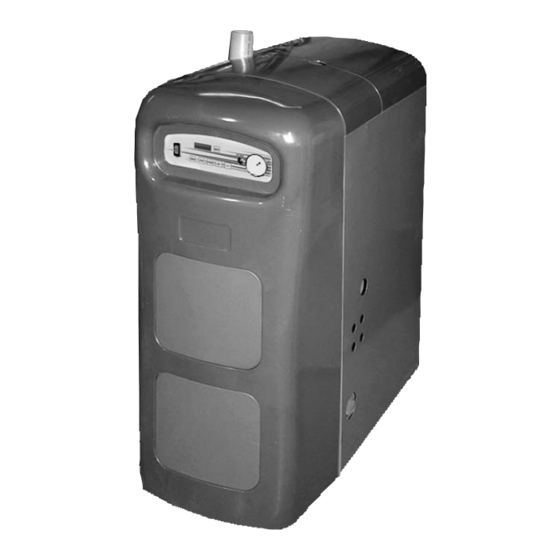
MODULATING HOT WATER BOILER
WARNING
!
Revise boiler control parameters only if you fully
understand the purpose and result of the chang-
es and on the advice of ECR Technical Support.
Tampering without understanding the control
settings in this manual will void the warranty
and can result in unreliable operation, with pos-
sible severe personal injury, death, or substan-
tial property damage.
WARNING
!
This document must only be used by a qualified
heating installer or service technician. Read all
instructions, including the Installation Manual
(P/N# 240006103), the Control Manual and Oper-
ating Instructions (P/N# 240006104), the User's
Information Manual (P/N# 240006106), and this
Parameter Guide before attempting to program
the control, and be sure to perform all steps in
the order specified. Failure to comply could re-
sult in severe personal injury, death, or substan-
tial property damage.
IMPORTANT: Installation must comply
with local requirements and with the Na-
tional Fuel Gas Code, ANSI Z223.1 for U.S.
installations or CSA B149.1 or B149.2 for
Canadian installations.
DO NOT DESTROY THESE INSTRUCTIONS!!
Please read carefully and keep in a safe place
for future reference.
95M-200
GAS-FIRED DIRECT VENT
P/N 240006105, Rev. A [04/08]
Advertisement
Table of Contents

Related Manuals for ECR International 95M-200


Summary of Contents for ECR International 95M-200
- Page 1 95M-200 GAS-FIRED DIRECT VENT MODULATING HOT WATER BOILER WARNING Revise boiler control parameters only if you fully understand the purpose and result of the chang- es and on the advice of ECR Technical Support. Tampering without understanding the control settings in this manual will void the warranty...
-
Page 3: Table Of Contents
95-200M GAS FIRED DIRECT VENT MODULATING HOT WATER BOILER PaRameteR guide Printed in USA • Made In USA TABLE OF CONTENTS i - Safety Symbols and Warnings ....... 3 ii - Overview of Control Parameters ....4 iii - Parameter explinations ........ 6 iV- How to Set Parameters .......11 V - Parameter Reference table ...... -
Page 4: Overview Of Control Parameters
II - Overview of Control Parameters differential and how to adjust.) BOILER CONTROL pARAMETERS High-mass Systems: High-mass systems, such as in-slab this manual includes detailed explanations of the adjustable radiant and cast iron radiator systems, respond slowly to parameters. See Section iii, “Parameter Explanations,” for heat input. - Page 5 II - OVERVIEW OF CONTROL pARAMETERS DEFAULT REV C pARAMETER SETTINGS ON GASCOM SOFTWARE AND BOILER DISpLAy DO NOT CHange any PaRameteR unLeSS tHe aPPLiCatiOn RequiReS SPeCiaL SettingS. DISpLAy PARAMETER/DESCRIPTION GASCOM t3 Set dHW 150°F dHW System CH System t1 top CH-mode 180°F t1 Foot CH-mode 120°F...
-
Page 6: Parameter Explinations
III - parameter Explinations required pick-up times and variations in heating load WARNING requirements by automatically increasing set point tem- Revise boiler control parameters only if you perature when a call for heat exceeds a specified time fully understand the purpose and result of the (Parameter 11). - Page 7 III - pARAMETER EXpLANATIONS Figure #2 perature is less than t4 minimum (Parameter 6). t1 Foot (Parameter 5) is the outlet water temperature TypICAL RESET CURVES Outdoor Reset Example A the boiler tries to maintain whenever the outside tem- perature is higher than t4 maximum (Parameter 7). M/R Limit When outside temperature is between t4 maximum A/R Limit...
- Page 8 III - pARAMETER EXpLANATIONS each minute the thermostat is open. greater than the value of Parameter 4 (t1 top). there Range: 1-30 minutes. is no concern that temperature boost would supply Factory default: 30 minutes. water too hot for low-temperature systems, such as deactivate automatic temperature boost by setting to slab-type radiant heating.
-
Page 9: Minimum Fan Speed
III - pARAMETER EXpLANATIONS heating and dHW using Parameters 13 and 15. BOILER FIRING RATE VS. RpM parameter 13 (space heating max. fan speed): % Rate BTUH Boiler Display • acceptable Range for natural gas and LP: 2250 to 80,000 2250 6000 rpm (22 to 60 on boiler display). - Page 10 III - pARAMETER EXpLANATIONS • Space heating differentials (parameters 22 and 23) the factory default setting for Parameter 23 is 4° F. this works well for most applications. • the term “differential” is also referred to as “hysteresis.” • For low mass systems (fan coil), performance can be •...
-
Page 11: Iv- How To Set Parameters
IV- How To Set parameters BOILER DISpLAy using the six buttons on the front of the boiler (below) and the proper code, the boiler can be both monitored and modified using the digital display. Perform the following steps with the boiler powered on and in standby [STBy] mode: Press the “SteP”... -
Page 12: Parameter Reference Table
V - parameter Reference Table Range Boiler Display Para. Name Display Position Description Gascom Boiler Software Display • T3 is the DHW temperature by an immer- sion sensor. • DO NOT CHANGE this parameter from Storage dHW: 68° to 158°F the factory setting. - Page 13 V - pARAMETER REFERENCE TABLE continued Range Boiler Display Para. Name Display Position Description Gascom Boiler Software Display initial reading: When outside temperature drops to this t4 Frost -22° to 50°F -22 to 50 number, the boiler circulator will run con- Protection after 2 to 3 seconds: stantly.
-
Page 14: Minutes
V - pARAMETER REFERENCE TABLE continued Range Boiler Display Para. Name Display Position Description Gascom Boiler Software Display • Use this parameter to increase the mini- initial reading: mum input of the boiler. increasing fan speed increases boiler input; decreasing minimum fan 22 to 60 2250 to 6000... -
Page 15: Seconds
V - pARAMETER REFERENCE TABLE continued Range Boiler Display Para. Name Display Position Description Gascom Boiler Software Display • Differential may also be referred to as initial reading: “hysteresis” • This parameter has no effect unless a dHW detec- dHW sensor is used - not recommended tion differen- -2°... -
Page 16: 2Nd Ch-Circuit Off
V - pARAMETER REFERENCE TABLE continued Range Boiler Display Display Position Para. Name Description Gascom Boiler Software Display First digit (2nd circuit): initial reading: • DO NOT CHANGE parameter 34 first dig- it. Second central heating circuit operation is not currently supported . •... -
Page 17: Hot Water Pump
V - pARAMETER REFERENCE TABLE continued Range Boiler Display Para. Name Display Position Description Gascom Boiler Software Display initial reading: First digit (3-way valve): • Control module readout: Initial reading - P.35 (indicates Parameter 35) after 2 to 3 second, change the parameter setting: Position 1,2 = blank Position 3 = Parameter 35 first digit (3 way valve or pump) -
Page 18: 70°F
V - pARAMETER REFERENCE TABLE continued Range Boiler Display Para. Name Display Position Description Gascom Boiler Software Display initial reading: use this parameter, if desired, to manually -1 (auto op- set the boiler at a fixed input. The manual -1 (auto) manual fans- eration) operation will only continue for 15 minutes. -
Page 19: Parameter Change Record
VI - parameter Change Record Parameter Original Date of Reason for Parameter Change New Value Value No. Changed Change... - Page 20 For technical assistance with this product call toll free 1-800-325-5479 ECR International PO Box 4729 Utica, NY 13504-4729 www.ecrinternational.com...
Need help?
Do you have a question about the 95M-200 and is the answer not in the manual?
Questions and answers