Table of Contents
Advertisement
Quick Links
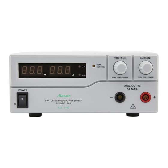
Laboratory Grade & High RFI Immunity Switching Mode Power Supply with Rotary Encoder Control
1. INTRODUCTION
Since the introduction of HCS series power supplies in 2009, we have made numerous improvement within the limits of
the original hardware modules, firmware and software framework.
In the upgraded version of HCS series power supplies, both the hardware and the firmware have been modified, the
application software has a completely design in concert with the value added features.
Added features which can be done on the unit panel.
1. Reset no load current to zero on current meter.
2. Reset the 3 presets to factory default
2. WARNING
•
Do not use this power supply near water.
•
Do not operate or touch this power supply with wet hands.
•
Do not open the casing of the power supply when it is connected to ac mains.
•
Refer all servicing to qualified service personnel only.
•
Before replacing the AC fuse at AC socket, find out and clear up the cause first.
•
Replace the AC fuse with the same type and rating as the original fuse.
•
The max. output voltage of Model HCS-3104 is over 60VDC, avoid touch the metal contact part of the output
terminals.
•
This power supply is designed for using in non-cascade environment. It is not recommended to connect two or more
power supplies in parallel or in series.
•
Analogue Remote Control or Remote Programming via USB function is only suitable for stand-alone one unit
operation.
•
Do not use this power supply with electrical motors, solenoid or inductive load that generates a back EMF and
voltage transient which may damage the power supply
3. CAUTION
•
Use a grounded 3 pin AC source.
•
This unit is for indoor use only.
•
Do not operate or place this unit in a humid, dusty, in direct sunlight location or near any heat source.
•
Before plugging into local AC mains, check with the rating label at the back of the unit.
•
Do not block any ventilation openings of the unit.
•
This unit must be used within the specified rating, regular excessive continuous loading may cause damage to the
power supply.
•
The gauge size of input power cable must be at least 0.75mm
3m.
4. OPERATION ENVIRONMENTAL CONDITION
•
10-80% R.H.
•
Altitude up to 2000m
•
Installation category: CAT 2
•
Pollution degree: 2
•
Mains supply voltage fluctuation up to ±10% of the normal voltage
HCS-3100/3102/3104
User Manual
2
and the total length of power cable must not exceed
Advertisement
Table of Contents

Related Manuals for Manson Engineering Industrial HCS-3100


Summary of Contents for Manson Engineering Industrial HCS-3100
- Page 1 HCS-3100/3102/3104 Laboratory Grade & High RFI Immunity Switching Mode Power Supply with Rotary Encoder Control User Manual 1. INTRODUCTION Since the introduction of HCS series power supplies in 2009, we have made numerous improvement within the limits of the original hardware modules, firmware and software framework.
-
Page 2: Controls And Indicators
HCS-3102: The total rated current (Aux.+Main) is 5A HCS-3104: The total rated current (Aux.+Main) is 2.5A Output Terminal (Rated 10A for HCS-3100/ Rated 5A for HCS-3102/ Rated 2.5A for HCS-3104) Mode Selection Switch (Normal, Preset, Remote Control, Set Modes) Recall Selection Switch... -
Page 3: Control Mode Selection
Output Voltage Output Current Maximum 13.8V Maximum HCS-3100: 15V Maximum HCS-3102: 25V HCS-3104: 55V 6.3 Set Mode – First enter into the Set Mode by pushing Switch (8) to Set Mode slot. The power supply is then ready to be preset. -
Page 4: Using The Power Supply
7.1 This series has 3 models. Make sure you have used the correct one. They have different output voltage range and current as following: Model Number Output Voltage Range Total Rated Current HCS-3100 1 ~ 18V 0 ~ 10A HCS-3102 1 ~ 36V... -
Page 5: Manually Zeroing Current Meter Offset
7.4 Using the control knobs The rotary encoder control knobs have fine and coarse tuning with clicking movement. Push the knobs to toggle between coarse and fine tuning, notice the subtle changes in brightness of related LED. . Adjust the knobs to your desired values by trying coarse and fine tuning. The display will resume its normal brightness after few seconds to confirm your adjustment. - Page 6 7.10 Reset 3 preset output P1/ P2/ P3 to factory default value In session 6.3, you learning how to set 3 preset output to you preferred value. In case you need to reset it to factory default, you can do it in MENU mode. Press and hold Voltage Control Knob for 30s to enter MENU mode.
-
Page 7: Analogue Remote Control Mode
8. ANALOGUE REMOTE CONTROL MODE There are two methods for remote control of current and voltage adjustment. Both methods require both the current remote control part and the voltage remote control part to be set up and be in used at the same time in order for analogue remote control mode to be functional. Otherwise unit will be in CC mode all the time and the analogue remote control will not be functional. -
Page 8: Remote Output On/Off Control
8.2 Method B Using two 0 – 5K Ohm variable resistors Two variable resistors must be set up at the same time in order for the remote control to be functional. Remark: variable resistors 5Kohm. Remote Socket Pin Assignment for variable resistor FUNCTIONS REMARKS Internal DC +5V... -
Page 9: Faults And Troubleshooting
9. FAULTS AND TROUBLE SHOOTING 9.1 OUP: Over Voltage Protection This unit has a built-in tracking over voltage protection feature. In the event of output voltage becoming greater than the set value (see specified range from specifications table), protection will be triggered and the output power will be cut off and OUP warning appears as below. -
Page 10: Specifications
10. SPECIFICATIONS Models HCS-3100 HCS-3102 HCS-3104 Output Variable Output Voltage 1 – 18VDC 1 – 36VDC 1 - 60VDC Variable Output Current 0 - 10A 0 - 5A 0 – 2.5A Voltage Regulation Load (10-100% Load) 50mV Line (90-264VAC Variation) -
Page 11: Pc Interface Control
11. PC Interface Control Support OS: Windows XP/Vista/7 (32bits/64bits) Driver: Silicon Lab CP210x USB driver (Included in CDROM folder “USB CP210x Drivers V6.6.1 for Win_XP_S2K3_Vista_7”) Execute Program: run “<CDROM Drive>:\pscs\pscs.bat” Main Display The Main interface divided into 7 panels. 1. Display panel – use to display real-time information of power supply. 2. - Page 12 Display panel The display show following information - Output Voltage value - Output Current value - Output Power value - Output On/Off status - C.V./ C.C. Model - Setting values Set output value and On/Off status You can directly type the desired output voltage & output current and then click “Set” button to set the value. Or you can use slide bar to adjust the value.
-
Page 13: External Timed Program
External Timed Program External Timed Program is completely controlled by PC, PC counts the time and changes voltage and current of power supply. Select External Timed Program tab to switch to the External Timed Program tab. - Double click on the cell that you would like to set value. For example Step 2 voltage. - Slide the bar to configure the value. - Page 14 Internal Preset Memory The PC interface remote mode really eliminates the tedious process in keying in groups of entries on the power supply. Because all the data are displayed together in the monitor, possibility of wrong entry is greatly reduced. Data of different groups can be classified, stored, exported and retrieved for use at any time.
- Page 15 Data Log Data Log window Data log window is used to display output Voltage, Current and Power against time in graphical view. You can move the diagram left and right by adjust “Move:” slide bar. You can zoom in/out the diagram by adjust “Zoom:” slide bar. You can save the data in CSV file for analysis later.
- Page 16 Click to open and load setting from CSV file to program. Click to print the setting to print. If you want to add description for your setting. Input the description in following “External Timed Program Description:” space to before save. When “Internal Preset Memory”...
- Page 17 I. Power Supply Calibration (Only available on Firmware 3.1 or above) * WARNING: IT IS HIGHLY RECOMMENDED THAT THE CALIBRATION IS DONE BY EXPERIENCE TECHNICAL PERSON HCS can be calibrated by using Manson PC control software. Digital Multi-meter and Electronic load are required for calibration.
- Page 18 Command Set Command line format COMMAND<parameter1><parameter2>... [CR] Remark: One decimal place for current value: HCS-3100, 3150, 3200, 3202 Two decimal places for current value: HCS-3102, 3104, 3204 Command code & return value Function Example Input Command: Get PS maximum Voltage &...
- Page 19 Command code & return value Function Example Input Command: Preset Voltage value Input command: VOLT<voltage>[CR] VOLT127[CR] <voltage>=000<???<Max-Volt Return value: Return value: OK[CR] *Max-Volt value refer to product specification OK[CR] Meaning: Set Voltage value as 12.7V Input Command: Preset Current value Input command: CURR<current>[CR] CURR120[CR]...
- Page 20 12. Appendix HCS USB configuration for remote programming This application note describes the procedure to configure the USB port for HCS remote programming application. HCS remote programmable power supply with USB can connected to PC through USB cable. USB to serial bridge design is used. When connected to PC, it will be converted as COM port shown in the following picture.
Need help?
Do you have a question about the HCS-3100 and is the answer not in the manual?
Questions and answers