Table of Contents
Advertisement
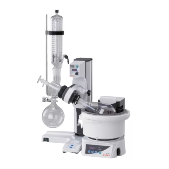
Rotary
Evaporator
Vacuum
N-1210 Series
IMPORTANT
This instruction manual is designed to use the product safely with keeping its best
performance.
Be sure to read "Safety precautions" before use.
Please keep this manual in a place easily accessible to every users.
Tokyo Rikakikai Co., Ltd.
取扱説明書
取扱説明書
Instruction Manual
取扱説明書
R00
Advertisement
Table of Contents

Related Manuals for EYELA N-1210 Series


Summary of Contents for EYELA N-1210 Series
- Page 1 Instruction Manual Rotary 取扱説明書 Evaporator Vacuum N-1210 Series This instruction manual is designed to use the product safely with keeping its best performance. Be sure to read “Safety precautions” before use. IMPORTANT Please keep this manual in a place easily accessible to every users.
- Page 2 Important Safety Notice 1. Warning Signal Word To ensure the safety, this manual defines the This unit is not explosion-proof. If you use flammable information on such matters as requiring particular substance/sample or organic solvents, take extreme care in the safety for each danger and attaches the care not to spill them.
-
Page 3: Table Of Contents
■Glass parts Package 3 Rotary joint ring Ball joint clamp Condenser Sample flask Receiver flask Rotary joint Eyela clip Capillary feed tube Ball joint clamp Eyela clip Rotary joint ring 9 Adapter 10 Vacuum nozzle set (white) 1 set 1 set... -
Page 4: For Safe Operation
For safe operation Do not touch the rotation parts while the flask is rotating Caution Do not touch the clip or the specimen flask while the flask is rotating. Your finger might be caught between protruding parts and grooves of the clip and get injured. Be cautions, high liquid temperatures bring the rise of burns Do not touch the sample flask or the bath when you use the product at high liquid Caution... -
Page 5: Product Outline
Product Outline 2-1 Application Warning Caution Never attempt to modify the product. Take care for conditions and Operate the unit for the specified purpose only. handling of glass parts An electric shock or a malfunction may result if the Broken or flowed glass parts may result in accidents. product is modified or used for any purposes other Inspect for damages or flows on glass parts and take than that specified. -
Page 6: Names Of Parts
Condenser Continuous Slide main body specimen supply port Driving unit Angle adjusting knob bolt Ball joint clamp Sample flask Eyela clip Receiving flask Stand base Power switch Jack up/down key Vacuum nozzle (white) Manual slide knob bolt Cooling nozzle(gray) Hose holder... - Page 7 Slide main body sample supply port Driving unit Adaptor Angle adjusting knob bolt Ball joint clamp Sample flask Eyela clip Stand base Receiver flask Power switch Jack up/down key Cooling nozzle (gray) Vacuum nozzle (white) Condenser support bar Set screw...
- Page 8 Slide main body Continuous sample supply Driving unit port Adaptor Angle adjusting knob bolt Ball joint clamp Specimen flask Eyela clip Stand base Receiver flask Power switch Jack up/down key Vacuum nozzle Condenser support bar Set screw Manual slide knob bolt...
-
Page 9: Names And Functions Of Control
Names and functions of control assembly 3-1 Control panel ②Run/Stop key Alarm Stop Rotation ③Speed indicator ①Power switch ④Rotation control knob Min position ⑤Rotation lamp ⑦Jack up/down key ⑥Alarm lamp Name Function ① Power switch Turning this ON to power on and the switch lamp comes on. Press this button to start rotation and press again to stop. -
Page 10: Installation 4-1 Installation Environment
Installation 4-1 Installation environment Warning Never install the product in a potentially hazardous atmosphere. The product is not explosion-proof. Use in a potentially hazardous atmosphere may cause a fire or other accidents. Select a place that meets the conditions below for installing this product: ●... -
Page 11: Connecting Utilities
4-2 Connecting utilities Warning Warning Do not use the branching socket or Confirm the voltage, phase, capacity, and the type of receptacle of power table tap. supply. Over-current may cause cable burn, fire. Wrong connection of power supply may cause fire or electric shock Warning Connect the ground wire correctly. - Page 12 Operation 5-1 Preparation for operation Caution Caution Be careful for jumping of the jack. Be sure to raise the jack before setting glass parts. This jack is always under a lifting force. First raise the jack before setting glass parts. If the When you release the lock, be sure to put your hand jack is raised during setting work, a personal injury on the jack.
- Page 13 2. Installing the rotary joint (1) Fit the rotary joint ring over the rotary joint. Rotary joint ring (2) With the flask removal screw installed on the drive Drive body body, insert the rotary joint and the rotary joint ring altogether into the drive body. (3) Securely insert the rotary joint until it is hooked on the sleeve pin inside the drive assembly.
-
Page 14: Condenser
Nozzle packing Vacuum nozzle (white) Set screw Coolant nozzle(gray) Housing Rotary joint Capillary feed Eyela clip tube Sample flask Condenser Ball joint clamp Receiver flask (1) Allow the condenser to tightly touch the vacuum (3) Fix the sample flask to the rotary joint with the seal in the housing and then tighten with the set Eyela clip. -
Page 15: Rotary Joint Ring
Cooler Vacuum nozzle (white) Cooler clamp Cooler support bar Adopter Capillary feed tube Rotary joint Eyela clip Specimen flask Ball joint clamp Set screw Receiver flask Set screw Housing (1) Fix the condenser support bar into the hole at the back of the unit using the set screw. -
Page 16: Adapter
Vacuum nozzle Cool trap Condenser clamp Adaptor Condenser support bar Capillary feed tube Rotary joint Eyela clip Sample flask Ball joint clamp Set screw Receiver flask Set screw Housing (1) Fix the condenser support bar into the hole at the (5) Fix the receiver flask to the condenser with the back of the unit using the set screw. - Page 17 5. Adjusting the angle of the drive body Angle adjusting knob bolt Caution Adjust the angle of the drive body while holding the condenser with a hand. When you loosen the angle adjusting knob bolt, the drive may suddenly incline from the weight of the cooler or sample flask and fall down and you might LOCK get injured by the broken glass.
- Page 18 Trap bulb (2) Install the trap ball and the specimen flask using Eyela clip the Eyela clamps. Sample flask (3) Set the bath, support the lower part of the front of the drive with one hand, gently loosen the manual slide knob bolt to adjust the height.
-
Page 19: Operating Procedures
5-2 Operating procedures Caution Caution Stop operating the unit if you notice Never touch the sample flask or the any abnormal conditions. bath during condensation. If you notice any abnormal condition, immediately The bath and the specimen flask will be hot during turn the power switch OFF and refer to the section condensation and there is a danger of burning. - Page 20 ※ If the rotary joint and the sample flask stick (5)To remove the sample flask, remove the Eyela clip, together and cannot be separated, remove them turn the flask removal screw as shown in the right...
-
Page 21: Causes Of Troubles And Solutions
Contact your dealer or the nearest service Causes of troubles and solutions center for troubles not listed here. Symptom Causes Solutions Turn the power switch OFF and insert The power plug is come off the AC the power plug into the outlet securely. outlet. -
Page 22: Maintenance And Check Up
Maintenance and check up 7-1 Cleaning and care of the product Caution Caution Never attempt to disassembly the Use a correct method and items for product. cleaning or caring the product. The unit contains parts with high voltage applied or may become hot, and disassembly may cause an When cleaning or maintaining the product, never electrical shock or an injury. -
Page 23: Disposal Of Products
8 Disposal of Products Disposal of product or part must be done according to the specified disposal method. Principal components parts and disposal method Components External dimensions Model Weight How to discard (mm) N-1210B-S Approx. 13kg 670(W)×359(D)×750(H) Request the disposal N-1210B-V Approx. -
Page 24: After-Sales Services
9 After-sales Services 1. In case the product does not function satisfactorily, 3. Repair during the guarantee period will be made check first referring page according to the guarantee stipulations. troubleshooting to see if this is actually a trouble. 2. If the product remains unsatisfactory even after 4. -
Page 25: Reference Material
Reference material Density Evap. latent Boil Vacuum level Formula heat hPa) Name of typical substances × Class (b.p) (℃) (g / cm ) (cal / g) (Molecular (molar weight) b.p=25℃ b.p=30℃ b.p=40℃ (1013hPa) (20℃) (1013hPa) formula) Atomo p Atomo p 74.1 Diethyl ether 34.6... -
Page 26: List Of Consumable And Replacement Parts/Optional Parts
List of Consumable and Replacement parts/ Optional parts N-1210B -S Type 9 -2 TS24 TS29 N-1210B -V Type 10 -2 TS24 TS29 N-1210B -T Type 10 -2 TS24 TS29 - 23 -... - Page 27 Sleeve pin Flask remover Rotary joint ring Eyela clip Code No. Std. Code No. Std. 192600 142540 Code No. Std. For TS29 Code No. Std. For TS29 217020 142550 For TS24 142650 245540 For TS24 For N-1200 For N・NE B all joint clamp...
-
Page 28: Fuse
Capillary feed tube Screw plug(seal plug) Nozzle packing Viton O ring for nozzle set (Teflon tube:500mm) No. Code No. Std. No. Code No. Std. Qty No. Code No. Std. No. Code No. Std. 202770 232840 142691 116540 TS19/40 For N・NE For N・NE For N・NE Angle adjusting knob bolt... - Page 29 Fixing plate for NVC-3000 230V Power Cord C Type 230V Power Cord B Type 230V Power Cord O Type Code No. Std. Code No. Std. Code No. Std. Code No. Std. 245372 245373 245371 269500 For N-1210 Fixing plate for PBX Communication cable Connecting cable NVC-PBX (NVC-3000)
- Page 30 Std. TS29/38 TS24/40 Specimen(Pear shaped)flask TS29/38 TS24/40 Code No. Chemical coating Chemical coating 50mL 116140 228240 116220 228310 100mL 116150 228250 116230 228320 200mL 116160 228260 116240 228330 300mL 116170 228270 116250 228340 500mL 116180 228280 116260 228350 116190 228290 116270 228360 116200...
Need help?
Do you have a question about the N-1210 Series and is the answer not in the manual?
Questions and answers