Table of Contents
Advertisement
Quick Links
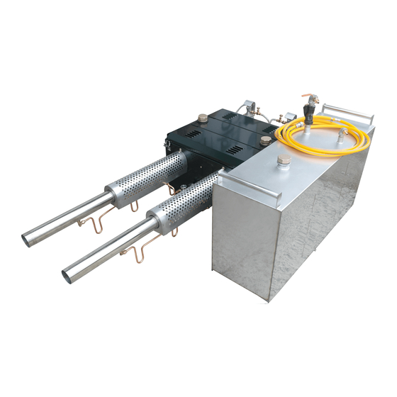
INSTRUCTION MANUAL THERMAL FOGGER VECTORFOG H500/H500SF
Only fog for short periods at a �me, when there is not much wind and moving away from the projec�ng smoke.
It's essen�al to read the manufacturer's instruc�ons of the chemical being used before you start applying, including
dilu�ng ra�o and safety precau�ons.
Only experienced personnel should operate this equipment.
You must exercise cau�on if fuel is spilt, in order to avoid the risk of fire.
Please read this manual before using the equipment.
You must wear protec�ve equipment (face/breathing mask, protec�ve clothing, gloves,
etc.) when handling poten�ally hazardous chemicals.
It is advisable to wear ear plugs to protect from the high noise produced by this machine
The interior of this machine heats up to extrem high temperatures. Do not add fuel or
chemicals during the opera�on of the machine or when it is hot a�er use.
Avoid fogging chemicals upwind.
High voltage can be dangerous. Do not turn on the machine when the spark plugs
electrode is exposed.
Experts in Fogging Technology™
CAUTION MARKS
1
Advertisement
Table of Contents

Related Manuals for Vector Fog H500

Summary of Contents for Vector Fog H500
- Page 1 Experts in Fogging Technology™ INSTRUCTION MANUAL THERMAL FOGGER VECTORFOG H500/H500SF Only fog for short periods at a �me, when there is not much wind and moving away from the projec�ng smoke. It’s essen�al to read the manufacturer’s instruc�ons of the chemical being used before you start applying, including dilu�ng ra�o and safety precau�ons.
-
Page 2: Specifications
SPECIFICATIONS Model H500/H500SF Type Vehicle Mounted Engine Pulse Jet Tank material & shape Stainless Steel / Rectangular Tank Capacity 150 Litres Droplet Size 10-30 Microns Flow Rate 80 Litres Per Hour Fuel Petrol Fuel Consump�on 4.5 Litres Per Hour Resonator Angle (SF Model Only) 0-45°... -
Page 3: Principles Of Operation
PRINCIPLES OF OPERATION VectorFog™ Thermal Foggers are powered using the pulse jet principle. Pulse jet engines don’t have any moving parts; instead they have a funnel shaped combus�on chamber similar to a rocket engine which opens into a long resonator or exhaust pipe. VectorFog thermal foggers have an auto start and operate through compressed air via a compressor. - Page 4 MAIN COMPONENTS (Cont…) FIG. 2 1. Air tube to carbure�or 5. Spark plug 2. Fuel flow control valve & Injector 6. Fuel hose 3. Carbure�or 7. 12V Power supply input 4. Fuel filter 8. Remote control input FIG .3 1. Rear access cover 4.
- Page 5 CHECKLIST BEFORE STARTING THE UNIT Fill the fuel tank Fill the tank with undiluted petrol using a funnel. Fill the tank to a third of its capacity. When you finish filling the tank, close the tank cap �ghtly. Note: Please make sure you only add the prescribed amount of fuel. 1.
-
Page 6: Maintenance
To turn on the machine Making sure that the solu�on switch on the remote control is on the “OFF” posi�on. Press the start bu�on (one resonator at a �me) and keep it pressed for 5 seconds a�er you hear combus�on star�ng (sounds like a small explosion). - Page 7 Fuel injector Maintenance Unscrew the fuel Injector situated on the back of the machine (FIG 2.4). Clean the injector with compressed air. FUEL REGULATOR INJECTOR NJECTOR Maintaining the valve petal Remove the top of the carbure�or. Check the gasket and valve for any distor�ons or cracks. If it’s damaged, you will need to replace this part.
-
Page 8: Troubleshooting
TROUBLESHOOTING If there is no ignition: • Listen for any noises coming from the engine If there is noise coming from the engine but there is no igni�on, this could be because the engine has flooded (an over-supply of fuel in the carbure�or). To solve this problem, first press the bu�on “KNOCKING” and then press the “START”... - Page 9 • Check the Petal Valve. Remove the spark plug cap, filter and unscrew the carbure�or. Examine the petal valve to see if it’s damaged. If it’s damaged, replace petal valve. TIP: It’s important to assemble the parts of the carburettor in the order there where disassembled.
- Page 10 • Unscrew the main chemical inlet nozzle from the resonator and clean it using compressed air to remove any blockages. • Check there is no leaks in the chemical tank. Blow compressed air backwards though the chemical tube from the inlet nozzle to see if any bubbles appear.
- Page 11 04. Carbure�or 1. Venturi 2. Upper Gasket 3. Cone sha� 4. Petrol valve board 5. Petrol valve 6. Petrol valve support 7. Spring washer 8. Bolt 9. Lower Gasket 10. Engine 11. Ejec�on nozzle 12. Nozzle 13. Ring 14. Nut 15.
Need help?
Do you have a question about the H500 and is the answer not in the manual?
Questions and answers