Table of Contents
Advertisement
Quick Links
Advertisement
Table of Contents

Related Manuals for Renogy ONE M1


Summary of Contents for Renogy ONE M1
- Page 1 Renogy ONE VERSION A1 QUICK GUIDE...
- Page 2 This Quick Guide contains important installation, operation, and maintenance instructions for Renogy ONE M1, hereinafter referred to as “Renogy ONE”. Please read the Quick Guide carefully before using the device. For additional support, contact our customer service through renogy.com/contact-us/. Renogy offers premium services worldwide: www.renogy.com...
-
Page 3: Table Of Contents
Table of Contents Package Contents ........................01 Product Overview ........................02 Wiring Diagram ........................04 Communication Diagram ......................05 Renogy ONE Communication Architecture ............... 05 Energy Device Communication Connections ..............05 Preparation ..........................07 Required Tools ........................07 Mounting Location ......................10 Power Wiring .......................... -
Page 4: Package Contents
Package Contents Quick Guide × 1 M2 Screws × 4 12V Power M4 Mounting Cable (5m) × 1 Screws × 4 ST2 x 1.2 x 6.5 mm ST4 x 2 x 13 mm VERSION A1... -
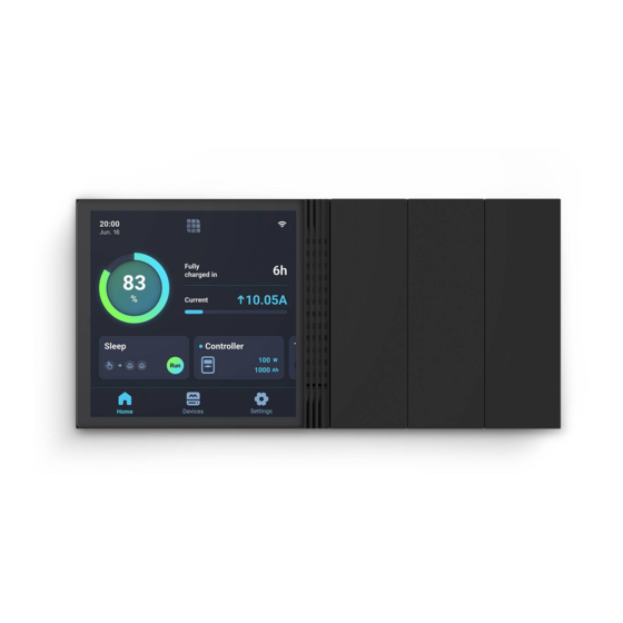
Page 5: Product Overview
Product Overview Part Part Power Button Panel Switch 2 Touch Screen Panel Switch 3 Panel Switch 1... - Page 6 IN 2 (External Load Input Terminal) RJ45 Port Alternate Power Input Port (Type-C, 5V, OUT 2 (External Load Output Terminal) 3.5W) z Please inspect Renogy ONE for any visible damage including cracks, dents, deformation, and other visible abnormalities before installation.
-
Page 7: Wiring Diagram
Illustrations in the Quick Guide are for reference only. z Renogy ONE is only suitable for safe use in areas below 2,000 meters above sea level. z There are no user serviceable parts inside Renogy ONE. Do not disassemble or attempt to repair it. -
Page 8: Communication Diagram
Charge Controller Inverter Battery Charger Devices To ensure good compatibility, it is recommended to use Renogy's energy devices and smart accessories. Energy Device Communication Connections Bluetooth 1. For devices with a built-in Bluetooth module or 2. For devices connected to Renogy... - Page 9 For REGO devices connected with RV-C daisy chain topology: RV-C Daisy Chain Topology Renogy ONE Device 1 RV-C RV-C Communication Communication Cable Cable RV-C Communication Cable Device 2 Device N For backbone topology, please contact our customer service through renogy.com/contact-us/.
-
Page 10: Preparation
Preparation Required Tools Mounting Location Required Tools z To prevent rework, please follow the installation steps below one after another. Required Tools Phillips Screwdriver (#1) Phillips Screwdriver (#2) Insulation Tape (for M2 Screws) (for M4 Screws) Skill Saw Measuring Tape Drill (1.5mm) - Page 11 Installation Mounting Template Please tear off this piece of paper and paste it to the mounting location for drilling holes. You can also use another piece of paper as the mounting template. The installation hole comes in 110 mm × 65 mm (4.33 in x 2.56 in). 65mm (2.56in) 110mm (4.33in)
- Page 12 Installation...
-
Page 13: Mounting Location
The extension cable should not exceed 10 meters (32.8 feet). z Ensure that the base cover of Renogy ONE is firmly mounted to the wall to prevent it from falling off. 12V DC... - Page 14 1.1.5 1.1.6 Tear off the mounting template. Remove the base cover of Renogy ONE with a Phillips screwdriver (#2). Put the protruding part of the base cover into the installation hole (in a direction and position as shown in Figure 1.1.7), and...
-
Page 15: Power Wiring
Power Wiring z Renogy ONE can be connected to a DC power supply of up to 16V; otherwise Renogy ONE may be damaged. z Illustrations in this quick guide are based on scenarios where REGO 12V 400Ah Lithium Iron Phosphate Battery and REGO 3 Ports 400A Battery Combiner Box are adopted as power supplies. - Page 16 Power Wiring Power on the DC power supply and check if Renogy ONE automatically turns on with the LCD lighting up.
-
Page 17: Communication Wiring (Optional)
For scenarios where the RVs are installed with RV-C buses and where relevant devices are connected in backbone topology, see the user manual of Renogy ONE for connection details. If an RV-C bus is not pre-installed in the RV, please follow the steps below. - Page 18 Communication Wiring (Optional) Ensure the selected communication cable is long Pre-embed the RJ45 connector of the enough to connect Renogy ONE to other devices. communication cable into the installation hole. If there is only one device, RV-C Daisy Chain topology...
-
Page 19: Load Wiring (Optional)
Ensure that the working current of an external DC load is less than or equal to 5A; otherwise Renogy ONE may be damaged. z Ensure that the output voltage of the DC power supply for an external DC load is less than or equal to 30V;... - Page 20 Load Wiring (Optional) Ensure that the DC power supply cable and the cable that is connected to the positive pole of the load (appliance) are connected to the same group of terminals. For example, “IN 1” and “OUT 1” are in a group. OUT 3 IN 3 OUT 2 IN 2 OUT 1 IN 1...
- Page 21 DC load (≤30V DC, ≤5A) Insert the reserved tray cable connecting to the positive terminal of the load (applicance) into the Renogy ONE output terminal (OUT), and use a Phillips screwdriver to turn the DC load wire hatch screw clockwise.
- Page 22 Load Wiring (Optional) Insert the tray cable connecting to the positive end of the DC power supply into the Renogy ONE input terminal (IN), and use a screwdriver to turn the wire hatch screw clockwise. Make sure all connections are...
-
Page 23: Mounting
Mounting z Make sure that Renogy ONE is installed securely to prevent it from falling off. Disassemble Panel Switch 1 and Panel Switch 3 from Renogy ONE. Put the Renogy ONE on the base, and use the Phillips screwdriver to tighten the... -
Page 24: Operation
For initial use, Renogy ONE guides you through WLAN connection, pairing, and device adding via the activation wizard. z You can tap Skip in the upper-right corner of the main interface on Renogy ONE to skip some of the wizard steps. You can re-complete the activation operations through Settings. -
Page 25: Add Devices
To ensure good compatibility, it is recommended to use Renogy energy devices and smart accessories. z For adding Bluetooth devices to Renogy ONE through the DC Home app, refer to the user manual of Renogy ONE at renogy.com. Power On/Off... -
Page 26: Control External Loads
Activation WLAN Pairing with App Add Devices Power On/Off External Loads Control External Loads The 3 panel switches of Renogy ONE correspond to 3 panel relays respectively. IN 1 OUT 1 IN 2 OUT 2 IN 3 OUT 3 CAN/RS485... -
Page 27: Maintenance
Maintenance For optimum performance, it is recommended to perform these tasks regularly. z Ensure the Renogy ONE is installed in a clean, dry and ventilated area. z Ensure there is no damage or wear on the cables. z Make sure the communication cable connectors and power connectors are secure. - Page 28 FCC Statement This device complies with Part 15 of the FCC Rules. Operation is subject to the following two conditions: (1) This device may not cause harmful interference. (2) This device must accept any interference received, including interference that may cause undesired operation.
- Page 29 Renogy Power PLUS Renogy Power Plus allows you to stay in the loop with upcoming solar energy innovations, share your experiences with your solar energy journey, and connect with like-minded people who are changing the world in the Renogy Power Plus community.
- Page 30 find relevant documentation or get more support via "Contact Us". Renogy reserves the right to change the contents of this manual without notice. Join the Renogy Power Plus Community by downloading the DC Home App. Find your e-warranty here, and more.
Need help?
Do you have a question about the ONE M1 and is the answer not in the manual?
Questions and answers