Table of Contents
Advertisement
Available languages
Available languages
Quick Links
Advertisement
Chapters
Table of Contents

Related Manuals for VALPES ER PREMIER


Summary of Contents for VALPES ER PREMIER
- Page 1 Interface de commande manuelle Manual control box Installation manual Manuel d’Installation et d’Utilisation Installation and Operation Manual Installations- und Bedienungsanleitung p.14 Manual de instalación y funcionamiento p.20 ALUMINIUM POLYCARBONATE...
- Page 2 Index Montage ............................. 3 Encombrements ......................... 4 Branchements électriques ......................5 Fonctionnement ......................... 5 À L’ATTENTION DES PROPRIÉTAIRES ET UTILISATEURS Merci d’avoir acheté cet appareil. Il assurera un fonctionnement sécurisé et optimal à condition d’être utilisé conformément aux instructions décrites dans ce manuel et de faire l’objet d’une maintenance appropriée. De manière importante, l’installateur et l’utilisateur doivent être formés afin d’éviter tout dommage matériel et tout dommage corporel pouvant potentiellement entraîner la mort.
-
Page 3: Montage
Montage Le Boîtier de commande manuelle est conçu pour être utilisé avec les actionneurs électriques ER PREMIER, ER PLUS, VR, VS et VT PLUS Orientations de montage conseillées pour ER Orientations de montage conseillées pour VR Orientations de montage conseillées pour VS Orientations de montage conseillées pour VT+... -
Page 4: Encombrements
Encombrements Plaque de fixation pour ER, VR et VS (F07) Plaque de fixation pour VS (F10) et VT PLUS DSBA3308 • Rév. 28/03/2022 • Evol. EV-22-53... - Page 5 Boîtier polycarbonate Boîtier aluminium DSBA3308 • Rév. 28/03/2022...
-
Page 6: Branchements Électriques
Vérifier les indications portées sur la plaque d’identification de l’actionneur : elles doivent correspondre à votre réseau électrique d’alimentation. ER PREMIER : DSBA3100 ER PLUS : DSBA3200 ... -
Page 7: Fonctionnement
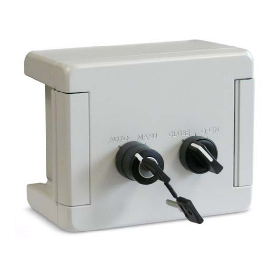
Fonctionnement AUTO Le mode de fonctionnement est le mode par défaut. Il donne la priorité de fonctionnement au câblage électrique classique des bornes 1, 2 et 3. En l’absence de maintien manuel, le commutateur reprendra cette position. MANU Le mode de fonctionnement est accessible uniquement quand la serrure est déverrouillée et nécessite un maintien physique du commutateur. - Page 8 Index Mounting ............................ 3 Dimensions ..........................4 Electric connections ........................5 Operation ............................ 5 ATTENTION OWNERS AND USERS Thank you for purchasing the device. This equipment will provide safe and productive operation as long as it is used in accordance with the instructions in this Manual and is properly maintained. Importantly, unless the user is adequately trained and supervised, there is a possibility of death, serious personal injury, property damage or damage to the equipment.
- Page 9 Montage The manual control box is designed to be used with ER PREMIER, ER PLUS, VR, VS and VT PLUS electric actuators. Recommended mounting orientations for ER Recommended mounting orientations for VR Recommended mounting orientations for VS Recommended mounting orientations for VT+ The local control box takes place between the ISO5211 plate of the valve and the actuator one.
-
Page 10: Mounting
Dimensions Mounting plate for ER, VR and VS (F07) Mounting plate for VS (F10) and VT PLUS DSBA3308 • Rév. 28/03/2022... - Page 11 Polycarbonate version Aluminium version DSBA3308 • Rév. 28/03/2022...
-
Page 12: Electric Connections
Strictly observe the wiring and set-up instructions as described in actuators manuals: otherwise, the proper working of the actuator can not be guaranteed anymore. Verify that the indications given on the identification label of the actuator fully correspond to the characteristics of the electric supply. ER PREMIER : DSBA3100 ER PLUS : DSBA3200 ... -
Page 13: Operation
Operation AUTO is the operating mode by default . It gives operating priority to the conventional electrical wiring of terminals 1, 2 and 3. If not hold manually, the switch returns to AUTO position. MANU operating mode is available only when the button is unlocked and requires the switch to be physically held. - Page 14 Index Montage ............................. 3 Dimensionen ..........................4 Elektrische Verbindung ......................5 Betrieb ............................5 ACHTUNG EIGENTÜMER UND BENUTZER Vielen Dank für den Kauf des Geräts. Dieses Gerät bietet einen sicheren und produktiven Betrieb, solange es gemäß den Anweisungen in diesem Handbuch verwendet und ordnungsgemäß gewartet wird. Wichtig ist, dass, sofern der Benutzer nicht ausreichend geschult und beaufsichtigt ist, die Gefahr von Tod, schwerer Körperverletzung, Sachschaden oder Beschädigung des Geräts besteht.
-
Page 15: Montage
Montage Die lokale Steuerbox ist für die Verwendung mit ER PREMIER, ER PLUS, VR, VS und VT PLUS konzipiert worden . Empfohlene Montageausrichtungen für ER Empfohlene Montageausrichtungen für VR Empfohlene Montageausrichtungen für VS Empfohlene Montageausrichtungen für VT+ Die Montage erfolgt zwischen der ISO5211-Schnittstelle des Ventils und der Schnittstelle des Stellantriebs ... -
Page 16: Dimensionen
Dimensionen Befestigungsplatte für ER, VR und VS (F07) Befestigungsplatte für VS (F10) und VT PLUS DSBA3308 • Rév. 28/03/2022... - Page 17 Polycarbonat-Gehäuse Aluminiumgehäuse DSBA3308 • Rév. 28/03/2022...
-
Page 18: Elektrische Verbindung
Halten Sie unbedingt die Reihenfolge der Anschluss- und Inbetriebnahmeanweisungen ein, die in den Handbüchern der einzelnen Stellantriebe beschrieben sind, da sonst die ordnungsgemäße Funktion nicht gewährleistet ist. Überprüfen Sie die Angaben auf dem Typenschild des Servomotors: Sie müssen mit Ihrer Stromversorgung übereinstimmen. ER PREMIER : DSBA3100 ER PLUS : DSBA3200 ... -
Page 19: Betrieb
Betrieb AUTO Der Betriebsmodus ist der Standardmodus. Er gibt der klassischen elektrischen Verdrahtung der Klemmen 1, 2 und 3 die Betriebspriorität. Wenn kein manuelles Halten erfolgt, nimmt der Schalter wieder diese Position ein. MANU Die Betriebsart ist nur zugänglich, wenn das Schloss entriegelt ist, und erfordert ein physisches Halten des Schalters. - Page 20 Índice Montaje ............................3 Dimensiones ..........................4 Conexiones eléctricas ........................ 5 Operación ........................... 5 DIRIGIDO A LOS PROPIETARIOS Y USUARIOS Gracias por comprar este dispositivo. Se Garantiza un funcionamiento seguro y óptimo siempre que se utilice de acuerdo con las instrucciones descritas en este instructivo y que sea objeto de un mantenimiento adecuado. Es importante que el instalador y el usuario están adecuadamente capacitados y supervisados para evitar cualquier daño material y lesiones personales que puedan conducir a la muerte.
- Page 21 Montaje La caja de control manual está diseñada para utilizarse con los actuadores eléctricos ER PREMIER, ER PLUS, VR, VS y VT PLUS Orientaciones de montaje recomendadas para ER Orientaciones de montaje recomendadas para VR Orientaciones de montaje recomendadas para VS Orientaciones de montaje recomendadas para VT+ El montaje se realiza entre la placa ISO5211 de la válvula y el actuador.
- Page 22 Dimensiones Placa de fijación para ER, VR y VS (F07) Placa de fijación para VS (F10) y VT PLUS DSBA3308 • Rév. 28/03/2022...
- Page 23 Carcasa de policarbonato Carcasa de aluminio DSBA3308 • Rév. 28/03/2022...
- Page 24 Respetar obligatoriamente el orden de las consignas de conexión y de las puestas en marcha descritas en el manual al fin de garantizar el buen funcionamiento. Verificar las indicaciones puestas sobre la placa de identificación del actuador : deben corresponder a su red eléctrico de alimentación. ER PREMIER : DSBA3100 ER PLUS : DSBA3200 ...
- Page 25 Operación AUTO El modo de funcionamiento es el modo por defecto. Da prioridad de funcionamiento al cableado eléctrico convencional de los terminales 1, 2 y 3. Si no se aplica ninguna retención manual, el interruptor volverá a esta posición. MANU Sólo se puede acceder al modo de funcionamiento cuando la cerradura está...
Need help?
Do you have a question about the ER PREMIER and is the answer not in the manual?
Questions and answers