Table of Contents
Advertisement
Quick Links
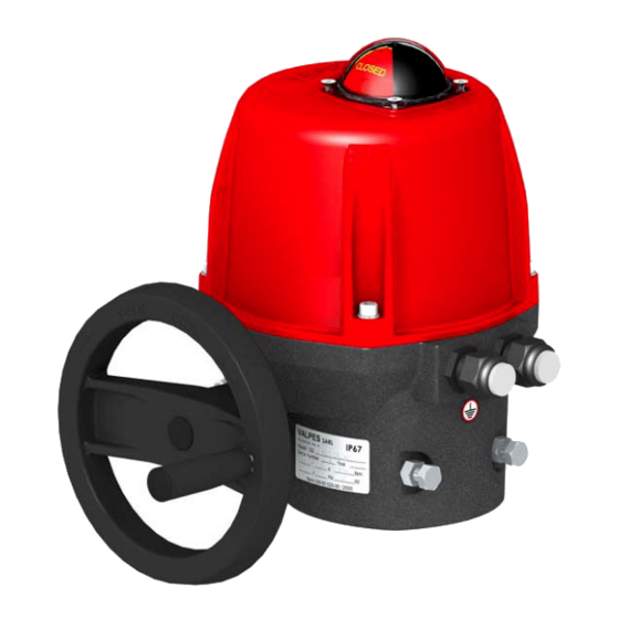
ACTIONNEUR ELECTRIQUE
ELECTRIC ACTUATOR
ELEKTRISCHER STELLANTRIEB
VALPES Valve Control System
ZI CENTR'ALP - 89 rue des Étangs - F 38430 MOIRANS
Tél. : (+33) 04-76-35-06-06
E-mail : info@valpes.com / Site web : www.valpes.com
DSBA2800 rév.21/06/06
FR
GB
D
Fax : (+33) 04-76-35-14-34
DOCUMENTATION TECHNIQUE
MISE EN SERVICE
TECHNICAL LITERATURE
SET UP PROCEDURE
TECHNISCHE UNTERLAGEN
BETRIEBSANLEITUNG
100-150-300
VS
1/19
Advertisement
Table of Contents

Related Manuals for VALPES VS Series


Summary of Contents for VALPES VS Series
- Page 1 SET UP PROCEDURE TECHNISCHE UNTERLAGEN BETRIEBSANLEITUNG VALPES Valve Control System ZI CENTR’ALP - 89 rue des Étangs - F 38430 MOIRANS Tél. : (+33) 04-76-35-06-06 Fax : (+33) 04-76-35-14-34 E-mail : info@valpes.com / Site web : www.valpes.com DSBA2800 rév.21/06/06 1/19...
-
Page 2: Table Of Contents
Index FRANCAIS Instructions......................3 Montage mécanique..................4 Branchements électriques ................5 ENGLISH Instructions......................6 Mechanical mounting ..................7 Electric connection ....................8 DEUTSCH Instruktionen......................9 Mechanische Montage ..................10 Elektrische Verbindung ..................11 ANNEXES Schéma électrique ..................12 APPENDICES Electric wiring ANHÄNGE Schaltplan Données techniques .................. -
Page 3: Instructions
100% des actionneurs ont été testés et réglés en usine. • Les produits VALPES sont garantis 2 ans ou 50000 manœuvres contre tous vices de fabrication et de matière, à partir de la date de livraison (facteur de service et classe du modèle suivant la norme CEI34). -
Page 4: Montage Mécanique
Montage mécanique DIMENSIONS DE L’ACTIONNEUR • L’actionneur est par défaut en position fermée. • Fixations possibles : F07 (4xM8 sur Ø70) et F10 (4xM10 sur Ø102), étoile 22, profondeur 24mm. • Ne pas monter l’actionneur « tête en bas ». •... -
Page 5: Branchements Électriques
Branchements électriques RESPECTER LES CONSIGNES DE SECURITE Nos presse-étoupes (annexe p.14 rep.15) acceptent un câble de diamètre compris entre 7mm et 12mm. Les câbles utilisés doivent supporter l’atmosphère ambiante (température maxi 70°). • Retirer l’indicateur visuel, dévisser les 4 vis et retirer le capot. CABLAGE DE L’ALIMENTATION ET DE LA COMMANDE •... -
Page 6: Instructions
DESCRIPTION The electric actuators VALPES have been designed to perform the control of a valve with 90° rotation. Please consult us for any different application. Valpes cannot be held responsible if the mentioned actuators are used in contradiction to this advice. -
Page 7: Mechanical Mounting
Mechanical mounting DIMENSIONS OF THE ACTUATOR • The actuator is set to its closed position in our factory. • Possible fixations : F07 (4xM8 with Ø70) and F10 (4xM10 with Ø102), star 22, depth 24mm. • Do not mount the actuator « upside down ». •... -
Page 8: Electric Connection
Electric connection RESPECT SAFETY INSTRUCTIONS Our cable glands (appendix p.14 mark 15) are designed for cables with a diameter between 7mm and 12mm. The used cables must be able to withstand the ambient conditions (maximum temperature 70°C). • Remove the position indicator, unscrew the four screws and take off the cover. SUPPLY AND CONTROL WIRING •... -
Page 9: Instruktionen
Instruktionen BESCHREIBUNG Die elektrischen Stellantriebe VALPES wurden entwickelt, um Ventile mit Vierteldrehung zu steuern. Bitte ziehen Sie uns vor jeder anderen Verwendung zur Rate. Für jeglichen weitergehenden Einsatz können wir keine Verantwortung übernehmen. SICHERHEITSHINWEISE Vor jeglicher Installation des Produktes zu lesen •... -
Page 10: Mechanische Montage
Mechanische Montage MASSE DES STELLANTRIEBES • Der Stellantrieb wird mit Voreinstellung Position geschlossen geliefert. • Mögliche Befestigungen : F07 (4xM8 bei Ø70) und F10 (4xM10 bei Ø102), Stern 22, Tiefe 24mm. • Den Stellantrieb nicht kopfüber anbringen. • Notwendige Höhe zur Anbringung des Stellantriebes : H=360mm über dem Ventil. HANDNOTBETÄTIGUNG UND EINSTELLUNG DER ENDHALTERUNGEN Der Stellantrieb wird vorrangig elektrisch betrieben. -
Page 11: Elektrische Verbindung
Elektrische Verbindung BEACHTEN SIE UNBEDINGT DIE SICHERHEIT ANWEISUNGEN Unsere Kabelverschraubungen (Anhang Seite 14 Markierung 15) sind zulässig für Kabel mit einem Durchmesser zwischen 7mm und 12mm. Die verwendeten Kabel müssen der Umgebungsluft standhalten (maximale Temperatur 70°C). • Den Stellanzeiger abziehen, die vier Schrauben lösen und die Haube abnehmen. VERKABELUNG DER STROMZUFUHR UND DER STEUERUNG •... -
Page 12: Schéma Électrique
Schéma électrique : Série V standard FR GB Electric wiring : standard V range Schaltplan : standard V Serie CABLAGE CLIENT SUGGERE SUGGESTED CUSTOMER WIRING DESIGNATION EMPFOHLEN VERDRAHTUNG BESCHREIBUNG FC0 Fin de course ouverture Mode 3 points modulants Mode Tout ou rien Open limit switch 3-points modulating mode On-Off mode... -
Page 13: Données Techniques
Données techniques Technical data Besondere Bedingungen DONNEES TECHNIQUES / TECHNICAL DATA Type (actionneur électrique 1/4 tour) VS100 VS150 VS300 Type (1/4 turn electric actuator) Protection IP / IP protection (EN60529) IP67 Résistance à la corrosion (utilisation en Enveloppe : Aluminium + peinture EPOXY / Housing : Aluminium + EPOXY paint intérieur et extérieur) Entraîneur : acier + traitement Zn / Drive : Steel + Zn treatment Corrosion resistance (outdoor and indoor use) -
Page 14: Liste Des Pièces Détachées
Liste des pièces détachées FR GB Spare parts list Ersatzteilliste VS100-150-300 Rep. Désignation Designation Bezeichnung Visual position indicator Stellungsanzeige Indicateur visuel de position Capot Cover Haube Vis inox Stainless steel screws Edelstahl Schrauben Motor Motor Moteur Pilot and power supply card Steuerung und Stromversorgung Karte Carte alimentation et commande Plaque réducteur... -
Page 15: Cartes Électroniques
Cartes électroniques FR GB Electronic cards Elektronische Karten Carte alimentation et commande AC30 Carte alimentation et commande AC60 Pilot and power supply card AC30 Pilot and power supply card AC60 Steuerung und Stromversorgung Karte AC30 Steuerung und Stromversorgung Karte AC60 Rep. -
Page 16: Codification
Codification : voir la page suivante pour les différents modèles FR GB Configuration : see next page for different models Kodifizierung : Siehe folgendes Blatt für weitere Modelle Exemple 1 ER 20 . X Example 1 Beispiel 1 Exemple 2 VS 150 . - Page 17 Table de référence Série VS FR GB VS Series reference table VS Serie Auswahl Tabelle Durée sous tension / Duty cycle / ED S4-30% Code Etoile/fixation Couple maxi Tensions Puissance Temps de man, Star/Fixation Maximum torque Voltages Power Travel time Stern/Anschluss Max.
-
Page 18: Déclaration Ce
à laquelle ils sont intégrés. VALPES part-turn actuators covered by this Declaration must not be put into service until the entire machine, into which they are incorporated, has been declared in conformity with the provisions of the directive. -
Page 19: Formulaire De Retour Produit
Panne Commentaires Motif Tél. : (+33) 04.76.35.06.06 Fax : (+33) 04.76.35.14.34 (pannes, Révision E.mail : info@valpes.com conditions de Site web : www.valpes.com service,…) Remise en stock VALPES N°…………………... Defect report sheet on …………………. Form to returned with delivery note Contact...
Need help?
Do you have a question about the VS Series and is the answer not in the manual?
Questions and answers