
Related Manuals for Moons' Lin Engineering R701P


Summary of Contents for Moons' Lin Engineering R701P
- Page 1 16245 VINEYARD BLVD, MORGAN HILL, CA 95037 TEL. 408.919.0200 FAX. 408.919.0201 WWW.LINENGINEERING.COM R701P MICROSTEPPING DRIVER USER MANUAL VERSION 6.70 LIN ENGINEERING Page 1 Version 6.70 R701P User Manual 02/15/2022...
-
Page 2: Table Of Contents
TABLE OF CONTENTS Technical Support ......................1 1. FEATURES ........................4 Input Option Header ............................4 Using +5V, Common Ground, and Disable for Optos ................4 2. ELECTRICAL SPECIFICATIONS ................4 3. OPERATING SPECIFICATIONS ................. 4 Heatsinking ................................. 5 4. MECHANICAL SPECIFICATIONS ................5 Dimensions................................ -
Page 3: Technical Support
Thank you for purchasing the R701P Driver. This product is warranted to be free of manufacturing defects for one year from the date of purchase. Technical Support By Telephone: 408-919-0200 (Mon.-Fri., 8:00 a.m.-5:00 p.m.) By Email: techsupport@linengineering.com Our technical support group is glad to work with you in answering your questions. If you cannot find the solution to your particular application, or, if for any reason you need additional technical assistance. -
Page 4: Features
1. FEATURES R701P • 10 microstepping driver • Common Ground or Common + 5 Volts Input Option Available • Optically isolated Step, Direction, and Disable/Enable inputs • Automatic Current Reduction • Adjustable trimpot for noise and vibration reduction • Operates from 18 to 80 VDC •... -
Page 5: Heatsinking
Heatsinking The R701P needs an additional heatsink for current settings greater than 3 Amps. The case temperature (measured from the bottom plate) should not exceed 70° C. For best results, use heatsink compound between the R701P and the heatsink. 4. MECHANICAL SPECIFICATIONS Size: 2.5”... -
Page 6: Pin Assignments
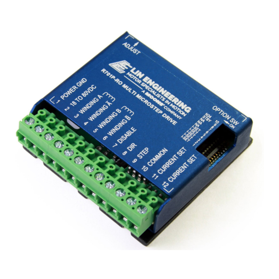
5. PIN ASSIGNMENTS PIN # FUNCTION DESCRIPTION The ground or return of power supply connects Power Ground here. Motor Supply Voltage. +18 to +80 VDC Phase A A of the stepping motor Phase A- A- of the stepping motor Phase B B of the stepping motor Phase B- B- of the stepping motor... -
Page 7: How To Connect
How to Connect For safety reasons, please connect the power supply (Terminal 2) last. Terminal 1: Power Ground - Connect the power supply ground here. Terminal 2: +18 to 80 VDC - Connect the positive (+) end of the power supply here. The maximum power supply current required is 67% of the motor’s rated phase current. -
Page 8: Resistor Values To Set The Current
These inputs are optically isolated from the rest of the drive. Terminal 10 is the common anode connection for the opto-isolators and must be connected to the +3.3VDC,+5 VDC supply of your indexer or pulse generator. These inputs are meant to be driven by 3.3V to 5.5V logic capable of sourcing or sinking 2.5 mA of current. -
Page 9: Resistor Values For The Opto Supply
Figure 3: Connections Diagram Resistor Values for the Opto Supply The optocouplers must be powered by an external power supply to maintain isolation. The Opto Supply (Terminal 10) for the optocouplers can be between +5 to 24 VDC with respect to the signal input. -
Page 10: Configuring And Control Of The R701P
7. CONFIGURING AND CONTROL OF THE R701P Adjust Trimpot This trimpot adjusts the motor for the smoothest possible low speed operation. Set the motor speed to about ¼ revolutions per second, and then, using a flathead screwdriver turn the trimpot until a distinct null is noted in the motor’s vibration. -
Page 11: Option Set Switches
Option Set Switches LIN ENGINEERING Page 11 Version 6.70 R701P User Manual 02/15/2022... -
Page 12: Main Connector
Main Connector The R701P uses a 2-piece modular main connector. The connector is split into two pieces: Terminals 1 through 6 (power supply and motor leads) and Terminals 7 through 12 (control interface). Each can be removed separately by pulling the connector body upwards and off of the mating header pins on the R701P. -
Page 13: Lead Wire Motor Connection (Full-Winding)
6 Lead Wire Motor Connection (Full-Winding) For a full winding connection, use both end wires, the center tap is ignored. (NC: No Connection). Figure 5.3: 6 Lead Wire Full Winding Connection 8 Lead Wire Motor Connection (Parallel Connection) Eight wire motors can be connected in two ways: Parallel and Series. When in parallel, the wires are simply connected such that the beginning of each winding are connected together. -
Page 14: Troubleshooting & Faq
9. TROUBLESHOOTING & FAQ The Motor is in Holding Position, but does not rotate: This means that Power is being supplied to the driver and motor, so the power supply is OK. However, the signal generator might be causing the problem. Try changing the signal to TTL. If this doesn't help, is the external +5 VDC Power connected? Be sure that the step pulses are a 0 to 5V squarewave with even on and off time.
Need help?
Do you have a question about the Lin Engineering R701P and is the answer not in the manual?
Questions and answers