Bernina Q Series Assembly Instructions Manual
Lift table
Hide thumbs
Also See for Q Series:
- User manual (78 pages) ,
- Service and maintenance manual (133 pages)
Table of Contents
Advertisement
Quick Links
Advertisement
Table of Contents

Related Manuals for Bernina Q Series


Summary of Contents for Bernina Q Series
- Page 1 Q Series Lift Table Assembly Instructions...
-
Page 3: Table Of Contents
Table of Contents Table of Contents IMPORTANT SAFETY INSTRUCTIONS ....Important information ........My BERNINA ............Introduction ............Overview of height-adjustable sit-down table ..Scope of delivery ............ Assembly .............. 11 Preparing legs ............11 Installing a substructure ......... 12 Installing foot parts .......... -
Page 4: Important Safety Instructions
Important safety instructions IMPORTANT SAFETY INSTRUCTIONS Note the following basic safety instructions when assembling the sit down table, and carefully read through the operating instructions for the BERNINA Q Series machine before using the sit down table. WARNING To protect persons from injuries: •... -
Page 5: Important Information
• The latest version of the assembly instructions can be downloaded at www.bernina.com. Proper use The sit-down table serves as a workstation for machines of the Q series, which are suited for use as sit down models. Any other use is not considered proper. BERNINA assumes no liability concerning consequences resulting from an improper use. - Page 6 Designates a low-risk hazard which can lead to minor or moderate injuries if not avoided. Designates a hazard which can lead to material damage if not avoided. NOTICE Tips from BERNINA quilt experts can be found next to this symbol.
-
Page 7: My Bernina
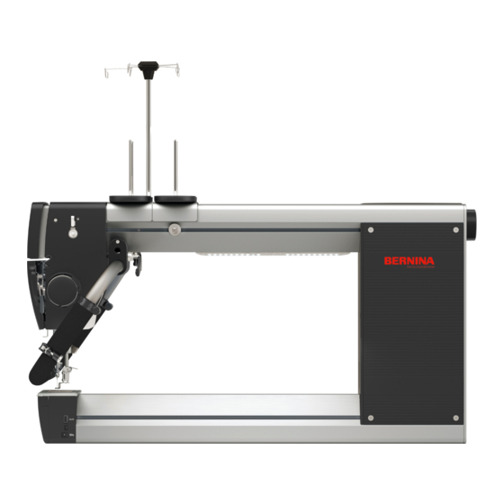
The height-adjustable sit-down table allows you to quilt comfortably while sitting or standing, using the machines of the BERNINA Q series, which are suited for use as table models. The electronic height adjustment makes it easier to switch between sitting and standing. - Page 8 My BERNINA Quantity Figure Name Box of installation accessories Rails with installation tool Cable clamps Wood screws, 4 × 16 Accessory insert mounts Hinges Fillister head screws, M6 × 20 Contents of box 2 Quantity Figure Name Table extensions...
- Page 9 My BERNINA Contents of box 3 Quantity Figure Cross bar consisting of: • 1 frame end [N1] • 1 frame end [N2] • 2 connecting rails [N3] Control unit, installed on [N2] Legs Rail supports Foot parts Without figure Power cable...
- Page 10 My BERNINA Quantity Figure Fillister head screws, M6 × 10 Operating unit Without figure Assembly instructions Allen key, 4 mm...
-
Page 11: Assembly
Assembly Assembly 2.1 Preparing legs Required parts: Required tools: • 1 cross bar [N] • Allen key [Y] • 1 control unit [O] • 2 legs [P] • 2 rail supports [Q] • 4 fillister head screws [U] • 8 fillister head screws [V] N1 N2 >... -
Page 12: Installing A Substructure
Assembly 2.2 Installing a substructure Required parts: Required tools: • 1 tabletop [A] • Phillips screwdriver (not included in the scope of delivery) • 1 leg [P-N1] preinstalled • Allen key [Y] • 1 leg [P-N2] preinstalled • 2 connecting rails [N3] •... -
Page 13: Installing Foot Parts
Assembly > Install the leg [P-N1] with three fillister head screws [L]. > Screw the connecting rails [N3] tight with eight fillister head screws [V]. > Insert the control unit [O] on the leg [P-N2]. > Install the operating unit [W] in the desired position (x) >... -
Page 14: Installing Accessory Insert Mounts
Assembly > Screw in two rails [G] at each end of the two foot parts > Screw the foot parts [R] tight to each leg with four fillister [R]. head screws [U]. 2.4 Installing accessory insert mounts Required parts: Required tools: •... - Page 15 Assembly > Pull out the extending elements as far as they will go. > Place the table extension [M] next to the table on the base, > Lift both levers on the right and left of the rail and pull out aligning the front edge with the front edge of the table the extending element fully.
-
Page 16: Turning The Table
2.7 Assembling the machine Installing BERNINA Q 16/Q 16 PLUS Required parts: • 1 BERNINA Q 16/Q 16 PLUS • 1 spacer [B] > Insert the machine and push it forward right up to the Upon delivery of the table, the spacer [B] is inserted in the spacer [B]. -
Page 17: Installing Inserts
Assembly Installing BERNINA Q 20 Required parts: • 1 BERNINA Q 20 • 1 spacer [B] > Insert the machine into the middle recess of the table and Upon delivery of the table, the spacer [B] is inserted in the push it all the way back. -
Page 18: Connecting The Control Unit
Assembly > Insert the cover [F]. > Insert flat accessory inserts [C] into the front openings. > Insert deep accessory inserts [D] into the rear openings. > Insert the lid [E]. 2.9 Connecting the control unit Required parts: • 1 power cable [S] >... -
Page 19: Manipulation
Manipulation Manipulation 3.1 Initializing the sit-down table The sit-down table must be initialized before it is first used. > Press and hold button (3) until the table has reached the bottom position. > Press and hold button (3) again until «RST» appears in the display (1). >... -
Page 20: Settings
Settings Settings In setting mode, the table moves below the bottom setting limit. Collision of the tabletop with obstacles NOTICE The settings cannot be implemented. > Before switching to setting mode, remove possible obstacles under the table. 4.1 Changing units Upon delivery, the table height is displayed in centimeters. -
Page 21: Configuring Collision Protection
Settings Changing the upper setting limit > Press and hold button (2) until the sit-down table has reached the desired maximum height. > Press button (7). > Press button (2). – «S-» flashes in the display (1). > Press and hold button (7) until «999» appears in the display (1). >... -
Page 22: Checking And Adapting The Bottom Setting Position
Settings > To change the value, press and hold button (2) until the desired value appears in the display (1). > When the desired value is displayed, release the button and wait until «RST» appears again in the display (1). >... -
Page 23: Errors And Faults
Errors and faults Errors and faults 5.1 Error messages Error message Explanation Remedy Height adjustment is overloaded. • Let height adjustment cool down for 20 minutes. Initialization required • Carry out initialization. (see page 19) Connection error • Check all cable connections. •... -
Page 24: Technical Data
Technical Data Technical Data Name Value Unit Setting range 72 – 121 (28 1/4 – 47 1/2) (in) Table width 124.5 (49) cm (in) Table width with extensions 200 (78 3/4) cm (in) Stroke speed without load cm/s (1.5) (in/s) Maximum load capacity 1000 Storage locations... - Page 26 BERNINA recommends threads from BERNINA International AG | CH-8266 Steckborn Switzerland | www.bernina.com | © Copyright by BERNINA International AG 1068985_00A_04 2022-02_EN...
Need help?
Do you have a question about the Q Series and is the answer not in the manual?
Questions and answers