Advertisement
Quick Links
Advertisement

Subscribe to Our Youtube Channel
Related Manuals for Bernina Q-matic on PRO Frame


Summary of Contents for Bernina Q-matic on PRO Frame
- Page 1 BERNINA Q-matic on PRO Frame Assembly Instructions...
- Page 3 Table of Contents Table of Contents Connecting the Y-drive ........... 63 IMPORTANT SAFETY INSTRUCTIONS ....Laying the cable in the energy chain ......63 WARRANTY AND LIABILITY REGULATIONS for Attaching the energy chain .......... 66 software ............... Connecting the cables on the Y-drive motor ....69 2.10 Connecting the machine .........
- Page 4 Do not view the LED light directly with optical instruments (e.g. magnifier). The LED light corresponds with protection class 1M. • When the LED light is damaged or defective, contact your BERNINA specialist dealer. WARNING To reduce the risk of burns, fire, electric shock or injury to persons: General facts •...
- Page 5 89.4 cm (35.2 inches). During assembly: • Before assembly, check all system components for transport damage. Contact a BERNINA specialist if system components need to be repaired or replaced. • Do not raise system components by their cables.
- Page 6 Important safety instructions • To disconnect, set the power switch on the control cabinet to «0» and then remove the plug from the outlet. • Remove the power cable from the outlet by pulling on the plug. Do not pull on the cable.
- Page 7 PRINTED USER GUIDE Registered users of BERNINA Q-matic software are permitted to create one (1) copy of the BERNINA Q-matic instruction manual for personal use. This can be printed using a private printer or a commercial printing office. LIMITED WARRANTY...
- Page 8 BERNINA or an authorized BERNINA representative has been advised of the possibility of such damages.
- Page 9 The BERNINA Q-matic automation system is conceived and designed for private household use. It is used for the automated quilting of quilt patterns that you create yourself using machines of the BERNINA Q Series on the quilting frame. Any other use is not considered proper. BERNINA assumes no liability concerning consequences resulting from an improper use.
- Page 10 Designates a low-risk hazard which can lead to minor or moderate injuries if not avoided. CAUTION Designates a hazard which can lead to material damage if not avoided. NOTICE Tips from BERNINA quilt experts can be found next to this symbol.
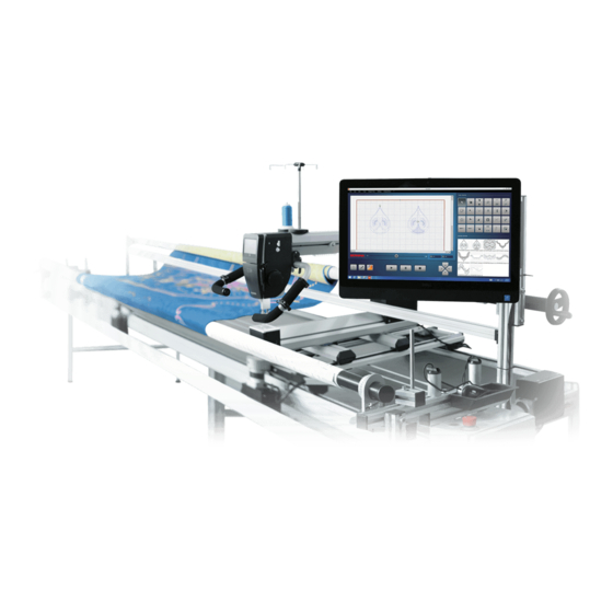
- Page 11 1.1 Introduction Large quilting projects can be created with the Q Series machines. The Q-matic automation system supports you when quilting with BERNINA Q Series machines on the quilt frame. The Q-matic automation system comprises: • Q-matic hardware, comprising mechanical and electronic parts, for automated machine movements on the quilt frame.
- Page 12 My Q-matic system 1.2 Overview Q-matic X-axis idler plate PC on mount Y-coupling X-drive motor Energy chain Control cabinet Y-axis idler plate X-drive belt Y-drive belt Y-drive motor Guidance for energy chain X-coupling...
- Page 13 > Check the individual parts for damage. > Check that the delivery is complete. > If parts are missing or if you have any questions about assembly, contact your BERNINA specialist. > Remove protective foils from the individual parts. 1.5 Delivery content for assembling the Q-matic Please note: Every tool not mentioned in the scope of delivery which is needed to assemble the Q-matic is supplied in the scope of delivery for the machine and the quilt frame.
- Page 14 My Q-matic system Packaging Figure Number Content Code Note BERNINA USB stick Installation instructions Instruction manual Icon sheet Packaging Figure Number Content Code Note X-drive belt, long Box A Drive motor X-axis idler plate Bag «X-axis Hex socket head cap...
- Page 15 My Q-matic system Packaging Figure Number Content Code Note Y-axis idler plate Profile Bag «Y-axis Button head screw Hardware M6x12 Set» Serrated lock washer Washer 6.2/12x1.6 Slot nut M6 2 pre-fitted on the Y-axis idler plate. Hex socket head cap 2 pre-fitted on screw M6x12 the Y-axis idler...
- Page 16 My Q-matic system Packaging Figure Number Content Code Note Box B Control cabinet Packaging Figure Number Content/Component Code Note Power cable (Q 20 / Q Box C Power cable (all-in-one Energy chain mount Energy chain End piece (with holes) M19A Is in the bag of the energy chain.
- Page 17 My Q-matic system Packaging Figure Number Content/Component Code Note Bag 1 X-coupling Button head screw, Torx M4x40 Threaded nut M4 Washer 4.3/12x1 Bag 2 Y-coupling Bag 3 Cable clamps Washer 5.3/10x1 1 x long Spiral cable binding M12A 1 x short Spiral cable binding M12B Hose pipes...
- Page 18 My Q-matic system Packaging Figure Number Content/Component Code Note Vario-Quick holding blocks KK Cable ties Countersunk screw, Bag 4 Torx M6x12 Slot nut M6 Countersunk screw, Torx M3x8 Threaded nut M3 Button head screw, Torx M4x40 Threaded nut M4 Bag 5 Profile...
- Page 19 My Q-matic system Packaging Figure Number Content/Component Code Note Bag 12 Hex socket head cap Bag 12 is screw M8x50 contained in bag 5. Washer M8 Slot nut M8 Hex socket head cap screw M6x16 Washer 6.4/18x1.6 Slot nut M6 Cover Hex stand-offs M4x12 Hex socket head cap...
- Page 20 My Q-matic system Packaging Figure Number Content/Component Code Note Washer 4.3/8x0.5 Bag 9 Hex socket head cap screw M8x80 Rubber cap Bag 10 Hex socket head cap screw M8x16 Washer M8 Slot nut M8 Bag 11 Adjustment weight for belt tension Gauge for belt tension with cord...
- Page 21 My Q-matic system Packaging Figure Number Content/Component Code Note Parallel pin hardened Ø 6x30 Packaging Figure Number Content Code Note Box D Guidance for energy chain Packaging Figure Number Content Code Note Box 2 All-in-one PC incl. cable, mouse and keyboard, quick start guide, warranty, safety and regulatory, USB stick "Windows 10...
- Page 22 Assembly Assembly 2.1 Preparation Fitting the slot nuts Two types of slot nuts are used for the installation of the Q-matic hardware. Type of slot nut Assembly Rectangular > Slide the rectangular slot nut into the groove from the profile end. >...
- Page 23 Before installing the Q-matic system, check whether the quilt frame has sufficiently large spacing between the legs. If not, an upgrade kit is available from a BERNINA specialist, with which the quilt frame can be extended to the required width.
- Page 24 Assembly Disassembling the mechanical channel locks If you have installed mechanical channel locks on your machine, these must be removed before installing the Q-matic hardware. 2.2 Assembling the X-drive The X-drive moves the machine sideways in both directions. X-axis idler plate (M2) X-drive motor (M1) X-coupling (M6) X-drive belt, long (M3)
- Page 25 Assembly Installing the X-drive motor Required parts and tools: From box A • 1 Drive motor (M1) • 1 X-drive belt (M3A) From bag "X-axis hardware set": • 2 Hex socket head cap screws torx (S1) • 2 Sliding blocks M6 (SN1) Additionally: •...
- Page 26 Assembly > Using a slotted screwdriver, remove the black cover on the right-hand side of the quilt frame below the vertical profile (1). > On the profile, measure 13.8 cm (5.4 inches) from the bottom and mark with a pen. > On the X-drive motor (M1), insert a hex socket head cap screw (S1) through each screw hole from the outside.
- Page 27 Assembly > Slide the X-drive motor upward until the lower edge reaches the marking, and screw in place. > Check the spacing to the bottom edge of the profile once more. Positioning the X-drive belt > Unscrew both countersunk screws on the head of the X-drive motor and remove the cover.
- Page 28 Assembly > Place the X-drive belt (M3A) around the axis with the toothed side facing inwards. > Lay the X-drive belt on the tabletops and guide it under the machine on the left-hand side of the quilt frame. > Reattach the cover. Attaching the X-axis idler plate Required parts and tools: From box A:...
- Page 29 Assembly From bag 9: • 1 Rubber cap (M27) Additionally: • Allen key no. 3 • Allen key no. 5 • Torx T10 screwdriver • Screwdriver, slot (not contained in the scope of delivery) > Remove the black cover on the left-hand side of the quilt frame below the vertical profile (1). >...
- Page 30 Assembly > Undo the pre-fitted slot nuts on the X-axis idler plate by 2–3 turns. > Insert the slot nuts on the X-axis idler plate from below into the front groove of the profile. > Slide the X-axis idler plate upwards until the lower edge reaches the marking. Tighten the screws only to the point that the X-axis idler plate can still be moved.
- Page 31 Assembly Tensioning the X-drive belt The X-drive belt must be pretensioned such that it is taut at the same height on both sides above the tabletops. The rubber cap (M27), which can be found in bag 9, is suitable to use as a gage. Prerequisite: •...
- Page 32 Assembly The X-coupling is installed on the left-hand side of the carriage. Required parts and tools: From bag 1: • 1 X-coupling (M5) • 2 Button head screws torx M4x40 (S2) • 2 Washers 4.3/12x1 (W1) • 2 Threaded nuts M4 (N1) Additionally: •...
- Page 33 Assembly > Move the X-coupling so that the black pins are flush with the belt at the front. > Tighten the screws. Closing the X-coupling > To close the X-coupling, position the coupling lever exactly vertical. > After closing the X-coupling, pull gently on the X-drive belt to ensure that the pin engages in a recess in the X-drive belt.
- Page 34 Assembly If the coupling lever releases unintentionally, the following tips may help: • Ensure that there is nothing on the tabletop which may impede the movement of the machine, and that the rails are free. • Ensure that the coupling lever is exactly vertical. •...
- Page 35 Assembly > Position the machine on the far left. > Open the X-coupling. > Guide the X-drive belt under the lower pin. > Place the adjustment weight in the center of the quilt frame over both drive belts.
- Page 36 Assembly > To tension the X-drive belt, tighten both setscrews uniformly on the X-axis idler plate using the Allen key. Ensure that both setscrews are tightened evenly; this is the only way that the X-drive belt can run freely in the idler plate. >...
- Page 37 Assembly > As a check, slide the machine over the entire length of the quilt frame and check whether the teeth of the X-drive belt touch the lower pin of the X-coupling. – If the teeth touch the pin, the X-drive belt must be tensioned tighter. >...
- Page 38 Assembly The Y-drive is installed on the carriage. Installation of the Y-drive requires the following steps: • Preparing the carriage (see page 38) « Installing the profiles « Installing the cable duct « Installing the energy chain mount • Installing the Y-drive motor (see page 42) •...
- Page 39 Assembly > In the rear profile (M7), place three slot nuts as follows: One slot nut (M6) in the front groove. Two slot nuts (M6) in the lower groove. > First, place a serrated lock washer (W 2) on each of all six button head screws (S3), then a washer (W3). Installing the profiles on the front >...
- Page 40 Assembly Installing the cable duct Required parts and tools: From box 1: • 1 Cable duct (M20) From bag 4: • 2 Button head screws torx M4x40 (S2) • 2 Threaded nuts (N1) Additionally: • Torx T20 screwdriver > Push apart the cable duct. Put the cover aside. It is only installed after laying the cables. >...
- Page 41 Assembly Additionally: • Allen key no. 4 • Torx T10 screwdriver The energy chain mount must be installed on the carriage at the rear on the left. > Remove transparent or gray protection foils if there are any. > Insert both countersunk screws into the screw holes of the end piece. >...
- Page 42 Assembly Installing the Y-drive motor Required parts and tools: From box A: • 1 Drive motor (M1) From the bag «Y-axis hardware set»: • 1 Y-drive belt (M3B) • 2 Hex socket head cap screws M6x12 (S4) Additionally: • Allen key no. 5 •...
- Page 43 Assembly Positioning the Y-drive belt > Unscrew both countersunk screws on the head of the Y-drive motor and remove the cover. > Place the Y-drive belt (M3) around the axis with the toothed side facing inwards. > Place the Y-drive belt on the carriage and guide it backward. >...
- Page 44 Assembly Additionally: • Allen key no. 3 • Torx T10 screwdriver Install the Y-idler plate at the back of the carriage. Prerequisite: • The profile at the back of the carriage is installed and the Y-idler plate has been placed in the profile. >...
- Page 45 Assembly > Place the Y-drive belt around the axis with the toothed side facing inwards. > Reattach the cover again. Pretensioning the drive belt > Pull the Y-idler plate carefully to the back by hand to pretension the belt. > Screw on the Y-idler plate loosely. >...
- Page 46 Assembly Installing the Y-coupling To prevent accidents and material damage, the Y-coupling opens automatically if the machine's movement is impeded by an obstacle on the tabletop or on the rails. The connection between the motor and the machine is interrupted; the machines only moves in the X direction. Required parts and tools: From bag 2: •...
- Page 47 Assembly > Align the slot nuts as shown on the left. > Insert the slot nuts into the groove on the machine underside between the front crossbar and the screw (1). Tighten the Y-coupling 50 mm (2 inches) from the front crossbar. NOTICE The nuts are inserted incorrectly The Y-coupling cannot be secured properly.
- Page 48 Assembly Closing the Y-coupling > To close the Y-coupling, position the coupling lever exactly vertical. > After closing the Y-coupling, pull gently on the Y-drive belt to ensure that the pin engages in a recess in the Y-drive belt. WARNING Risk of injury and material damage due to blocked coupling lever If the coupling lever has been intentionally blocked, the connection between the motor and the machine will not be interrupted in the event of an obstacle.
- Page 49 Assembly Tensioning the Y-drive belt The drive belts are too tightly tensioned. NOTICE Damage to the bearings due to too great a belt tension. > Check the belt tension. The drive belts are not tensioned enough NOTICE The quilt design will be quilted imperfectly. >...
- Page 50 Assembly > Hook the string into the adjustment gage. > Hook the adjustment gage in the right Y-drive belt. > Attach the adjustment weight to the string. > Place the parallel pin under the string. > Move the parallel pin slightly from one side to the other so that the adjustment gauge gets into position. >...
- Page 51 Assembly > Tension the Y-drive belt with the setscrew at the Y-idler plate so that the spacing between the adjustment gage and the left belt is 0.1–1.0 mm/0.004–0.04 inches. > If the adjustment gage touches the Y-drive belt, re-tension the Y-drive belt. >...
- Page 52 Assembly Required parts and tools: From box B: • Control cabinet (M10) From bag 10: • 2 Nuts PA-R M8 (SN3) • 2 Hex socket head cap screws M8x16 (S5) • 2 Washers M8 (W4) Additionally: • Allen key no. 3 •...
- Page 53 Assembly > Person 2: Tighten the screws from below. The slot nuts must rotate in the groove.
- Page 54 Assembly 2.5 Installing the all-in-one PC You can design your quilt project using the all-in-one PC with touch control and use it to sew automatically. All-in-one PC Screen holder Install the all-in-one PC on the right on the quilt frame. Installation of the all-in-one PC requires the following steps: •...
- Page 55 Assembly Required parts and tools: From box C: • 1 Screen holder (M21) From bag 5: • 1 Profile (M22) From bag 12: • 2 Hex socket head cap screws M8x50 (S8) • 2 Hex socket head cap screws M6x16 (S1) •...
- Page 56 Assembly > Screw the profile (M22) into the slot nuts (S1) using the hex socket head cap screws so that both profiles overlap by approx. 12.5 cm (5 inches). The height of the all-in-one PC can be adjusted at any point using these two screws.
- Page 57 Assembly > Move both of the lateral covers on the left and on the right of the screen holder into the notch from below, then press them upward in and together into the notches. > Fasten a cover on the top edge and bottom edge of the profile (M22). >...
- Page 58 Assembly > Install the four hex stand-offs on the reverse of the all-in-one PC. > Fit a washer on each of the four hex socket head cap screws. > Person 1: Hold the all-in-one PC to the screen holder so that the hex stand-offs exactly match with the drill holes in the screen holder.
- Page 59 Assembly 2.6 Installing the energy chain guidances 20 cm (7.8 in) 1,5 cm 7,5 cm (0.6 in) (3 in) Required parts and tools: From box D: • 3 Guidances (M17) From bag 4: • 6 Countersunk screws, Torx (S6) • 6 Nuts RF M6 (SN4) Additionally: •...
- Page 60 Assembly > Install the second energy chain guidance (2) with a spacing of 1.5 cm (0.6 inches) to the right next to the first energy chain guidance. 1,5 cm (0.6 in) > Install the third energy chain guidance (3) with the right edge 20 cm (7.8 inches) to the left next to the first energy chain guidance (1).
- Page 61 Assembly 2.8 Cable connections The six cables below are installed on the switchbox. Cable Approximate Beginning length Power supply, Y-drive motor 7.6 m (300 inches) Installed on the switchbox. Communication, Y-drive motor 7.6 m (300 inches) Installed on the switchbox. Power supply, X-drive motor 1.5 m (60 inches) Installed on the switchbox.
- Page 62 Assembly Cable Approximate Beginning length Communication, X-drive motor 1.5 m (60 inches) Installed on the switchbox. Communication, machine 6.5 m (255 inches) Installed on the switchbox. USB, all-in-one PC 1.8 m (70 inches) Installed on the switchbox. In addition, you can find three sockets for power cables on the right side of the switchbox. Top-down: Power supply, all-in-one PC (power cable C2) Power supply, Q 20/Q 24 (power...
- Page 63 Assembly All-in-one PC BERNINA Q Series machine 1 2 3 X-drive motor Y-drive motor 2.9 Connecting the Y-drive Laying the cable in the energy chain Required parts and tools: From box C: • 1 Energy chain (M19) • 1 End piece with knobs (M19B) •...
- Page 64 Assembly Preparing the cable > Insert the power cable (8) into the socket second from the top on the right side of the control cabinet. > Pull the three long cables (1, 2, 5) and the power cable (8) under the tabletop to the reverse side of the quilt frame.
- Page 65 Assembly 160 cm (68 in) 12 cm 90 cm (35.4 in) (4.7 in) Laying the cable in the energy chain > Place the energy chain next to the cables so that the end without end piece lies next to the cable tie which ties all four cables together.
- Page 66 Assembly > Push together the end piece with knobs (M19B) and fit at the end of the energy chain. Attaching the energy chain Required parts and tools: From bag 4: • 2 Countersunk head screw (S7) • 2 Threaded nut (N2) From bag 3: •...
- Page 67 Assembly > Bind the four cables and the end piece together using a cable tie. Cut the end off the cable tie. > Wind the spiral cable binding (M12B) around the four cables from the end of the energy chain, beginning from right to left.
- Page 68 Assembly Installing cables on the quilt frame Bundle the cables between the end of the energy chain and the control cabinet and install on the quilt frame as shown below. > Install up to three cable fastenings (M14) in the lower groove of the rear crossbar and two cable fastenings in the lower groove of the lateral bar.
- Page 69 Assembly Installing the energy chain on the carriage > Place the loose end of the energy chain over the installed end. > Move the carriage to the end of the energy chain. > Install the energy chain onto the end piece on the energy chain mount on the carriage (4). >...
- Page 70 Assembly Required parts and tools: From bag 3: • 1 Cable clamp (M11) • Cable ties (M15) Additionally: • Allen key no. 4 • Torx T10 screwdriver Laying the cable in the cable duct > At the end of the energy chain on the carriage, lay the Y-communication cable (2) and the Y-power cable (1) in the cable duct on the carriage.
- Page 71 Assembly > Guide the Y-communication cable (2) and the Y-power cable (1) through the openings on the left side into the housing. NOTICE Damage to the electronics due to electrostatic charge Components on the circuit board may be damaged by electrostatic charge during assembly. >...
- Page 72 Assembly > Attach the cover again. Laying the cable > Remove the rear screw at the top of the Y-drive motor. > Guide the cable through the cable clamp (M11). Install the cable clamp with the screw that was previously removed in the same place. >...
- Page 73 Assembly Additionally: • Torx T25 screwdriver > Plug the communication cable for the machine (5) into the back of the machine in the second lowest socket. Plug in the power cable of the machine (8) into the socket below the on/off switch. >...
- Page 74 Assembly > Remove the two screws at the bottom on the reverse side of the machine. > Push one screw through the drill hole of the cable clamp. Place four washers over the screw. > Tighten the screw in the right screwhole so that the cables form an arc to the right of the machine. >...
- Page 75 Assembly > Wind the spiral cable binding (M12A) around the two cables between the left cable clamp and the energy chain mount on the carriage. > On the energy chain mount, insert a cable tie through the two openings and around all cables, tighten it and cut the end off the cable tie.
- Page 76 Assembly > Remove the screws on the left and right of the rear handle. > Combine the cables with a cable protector (M13) and a cable clamp (M11). Tighten the cable clamp with a washer (W5) to the rear handle on the right-hand side using the screw previously removed. >...
- Page 77 Assembly 2.11 Connecting the X-drive • Torx T10 screwdriver > Undo three screws on the top and three on the bottom of the X-drive motor and remove the cover. > Guide the X-communication cable and the X-power cable through the openings at the bottom into the housing.
- Page 78 Assembly > Clip in the cable reliefs. > Attach the cover again. 2.12 Connecting the all-in-one PC Required parts and tools: From box C: • 1 Power cable for all-in-one PC (C2) > Insert the power cable for the all-in-one PC (C2) into the topmost socket on the right side of the control cabinet.
- Page 79 Assembly 2.13 Connecting the control cabinet Required parts and tools: From box 1: • 1 Power cable (C3) > Insert the power cable (C3) into the lowest socket on the right side of the control cabinet.
- Page 80 System Start-up System Start-up Risk of injury due to interventions in the running system WARNING Interventions in the system during automatic operation may lead to serious injury. > Do not touch any parts of the quilt frame or machine during automatic operation. >...
- Page 81 System Start-up Switching on the Q-matic system > Plug the power cable into the power outlet. > Switch on the control cabinet using the main switch (1). > To ensure that the emergency stop button is unlocked, rotate the button (3) in the direction of the arrow.
- Page 82 From box 1: • BERNINA USB stick > Insert a BERNINA USB stick into a USB port on the PC. > Open the «Q-matic» folder on the BERNINA USB stick. > Install the Q-matic software according to the instructions in the «Installation Guide» PDF.
- Page 83 > Check whether the USB cable to the all-in-one PC is correctly connected. Reconnect the cable if required. > Check whether the power cable to the machine is correctly connected. Reconnect the cable if required. > Restart the system again. > If the error persists, contact a BERNINA specialist or BERNINA technical support.
- Page 84 Index Index X-drive motor Connecting the cables............. 77 Adjusting the parking position .......... 60 Adjusting the X-drive belt ............. 34 Adjusting the Y-drive belt ............ 49 Y-drive Install the motor.............. 42 Y-drive motor Connecting the all-in-one PC .......... 78 Connecting the cables............. 69 Connecting the control cabinet..........
- Page 86 BERNINA recommends threads from BERNINA International AG | CH-8266 Steckborn Switzerland | www.bernina.com | © Copyright by BERNINA International AG 1018295.10A.04 2021-09 EN...
Need help?
Do you have a question about the Q-matic on PRO Frame and is the answer not in the manual?
Questions and answers