
Subscribe to Our Youtube Channel
Related Manuals for Halma Minicam Proteus VCU500


Summary of Contents for Halma Minicam Proteus VCU500
- Page 1 Van Control Unit and Desktop Keyboard VCU500 / VKU500 Original Instruction Manual Version A...
- Page 2 PLEASE NOTE For the purpose of this Original Instruction Manual Proteus VCU500 (Van Control Unit) will be referred ™ to using the abbreviation Proteus VKU500 (Desktop Keyboard) will be referred ™ to using the abbreviation...
- Page 3 This original instruction manual is applicable to the Proteus VCU500 (Van ™ Control Unit) and VKU500 (Desktop Keyboard). Disclaimer Hardware and software mentioned in this document are subject to continuous development and improvement. Consequently, there may be minor difference between the information in the document and the performance or design of the product.
- Page 4 Proteus VCU500/VKU500 Version A...
-
Page 5: Table Of Contents
Contents Warranty Limited Warranty Extent of the Limited Warranty Conditions of the Limited Warranty Warranty Limitations System Overview Typical System Setup EC Declaration of Conformity CE Declaration Maintenance Checking Plug and Socket Connections VCU500 Van Control Unit Product Overview Parts and Descriptions (Front) External media –... - Page 6 Parts and Descriptions Parts and Descriptions (Rear) ON/OFF button ALL STOP button Power ON sequence Power OFF sequence Crawler function keys Survey function keys Media function keys Camera function keys Snapshot key Recording and Playback keys QWERTY keys Joystick Control Pressurising Operation Mode Technical Specifications Technical Details - VKU500...
- Page 7 Enter the Section Header Information Start Your Survey Create a New Observation Review Your Survey End Your Survey Create Your Report Documents Detailed User Guide Using Projects Using Project Sections Preparing for the Survey Beginning the Survey Performing the Survey Ending the Survey Reviewing the Survey Creating a New Observation...
- Page 8 Proteus VCU500/VKU500 Version A...
-
Page 9: Warranty
Warranty Limited Warranty Congratulations on the purchase of your Proteus VCU500/VKU500 (Van Control ™ Unit and Desktop Keyboard). Our products are the result of many years experience and continuous developments. Conscientious manufacturing and checking are essential objectives in our company. Nevertheless failures cannot be excluded totally. -
Page 10: System Overview
System Overview The Van Control Unit and Desktop Keyboard has been designed and developed specially for the van-fit market. Ergonomically designed and manufactured to Mini-Cam’s rigorously high standards, the free-standing keyboard and under-shelf control unit replaces the traditional CCU to offer more flexibility for the user. -
Page 11: Ec Declaration Of Conformity
EC Declaration of Conformity CE Declaration We Mini-Cam Ltd. Unit 4 Yew Tree Way, Stonecross Park, Golborne, Warrington, WA3 3JD hereby declare that the product Proteus VCU/ ™ VKU500 to which this declaration refers is in compliance with the following standards or standardizing documents: Electromagnetic compatibility (EMC) EN61000-6-4: 2007 + A1: 2011... -
Page 12: Maintenance
Maintenance To ensure the Proteus VCU500 and VKU500 system operates reliably and ™ efficient, the individual modules have to be maintained and kept clean. Take notice of the following comments on general maintenance: • After regular use, keep the desktop keyboard clean by wiping with a lightly moistened cloth, use only clean water for cleaning. -
Page 13: Vcu500 Van Control Unit
VCU500 Van Control Unit Proteus VCU500/VKU500 Version A... - Page 14 Proteus VCU500/VKU500 Version A...
-
Page 15: Product Overview
Product Overview The Proteus VCU is a development of Mini-Cam’s best selling CCU208 ™ Crawler Control Unit. It is a screen-less control unit housed in a 1U high (44mm) rack mount enclosure so that it can be integrated into a 19” rack enclosure, in a typical van installation, with an industrial PC mounted in the van studio. -
Page 16: Parts And Descriptions (Front)
Parts and Descriptions (Front) A USB (A) port and LED D All Stop LED B USB (B) port and LED E Power ON/OFF LED C Eject USB Button F Motor Stop Button External media – USB ports External media status LED’s. •... -
Page 17: Parts And Descriptions (Rear)
Parts and Descriptions (Rear) A External Power Input (24VDC). This provides power for the system. B Serial number C Keyboard D USB to PC E Video output F Video output G VGA monitor output* H HDMI monitor output* J Connection to cable reel NOTE! *For optimum viewing on a PC screen, we recomend that the chosen monitor can support 4:3 format. -
Page 18: Powering The Van Control Unit
Powering the Van Control Unit The VCU may be powered from a vehicle 24 volt DC supply or from 240 volt AC via the standard Mini-Cam PSP24 power supply unit. Technical Specifications VCU500 - Van Control Unit Product Code VCU500 Frame Dimensions 483 x 271 x 43.6mm (W x D x H) Internal Width 433mm Weight 2.5kg (5.5lb) - Page 19 VKU500 Desktop Keyboard Proteus VCU500/VKU500 Version A...
-
Page 20: Product Overview
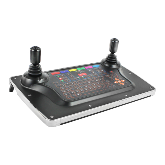
Product Overview The control unit VKU is a robust and portable control unit for the PROTEUS ™ system. It controls the functions and reports the status of the attached modules. It has the following features: • Scalable internal solid state storage (32GB minimum) •... -
Page 21: Parts And Descriptions
Parts and Descriptions A Left joystick - for crawler control B Crawler function keys C Survey function keys D ON/OFF button E ALL STOP button F Cable reel function keys G Media function keys H Camera function keys J Right joystick - for camera control K Snapshot key L Recording and playback keys M Arrow keys... -
Page 22: Parts And Descriptions (Rear)
Parts and Descriptions (Rear) M Connection to The desktop keyboard sports two neat retractable rear legs, to tilt and raise the keyboard for an alternative ergonomic position. Proteus VCU500/VKU500 Version A... -
Page 23: On/Off Button
ON/OFF button Power ON/OFF Used to turn the VCU . This button does not enable power to the crawler. By design, the VCU will power on but power is not STOP! automatically applied to the crawler. A green light next to this button indicates that the VCU is powered on. -
Page 24: Power On Sequence
Power ON sequence 1 With the system power , connect all system components: Cable reel, crawler, camera 2 Press button to power the control unit 3 Read and acknowledge the on-screen prompt. 4 Press the button. ALL STOP If the control unit detects a crawler connected, the system will fully power up. -
Page 25: Crawler Function Keys
Crawler function keys ▲ ▲ Cruise control - Forward • Each press increases speed until maximum speed is reached. • When the crawler is reversing, each press slows the crawler speed. Stop • Crawler stops moving. Power is still enabled. Cruise control - Reverse •... -
Page 26: Survey Function Keys
Survey function keys Meterage • Change meterage manually. • Change position of meterage on the screen. Text • Change text colour. • Display meterage and/or time and date on-screen. Survey Folder • Start ProPIPE+ or WinCan survey. Media function keys Copy •... -
Page 27: Camera Function Keys
Camera function keys Zoom Camera Illumination Focus- Focus+ Camera Home • Automatically move camera to home position (CAM026, CAM026L and CAM028L). Camera Settings Snapshot key Press this key to take a JPG image of the live video or video during play- back Proteus VCU500/VKU500 Version A... -
Page 28: Recording And Playback Keys
Recording and Playback keys These keys control the recording and playback of video files QWERTY keys These keys allow the user to enter text for on-screen text or survey com- ments. Proteus VCU500/VKU500 Version A... -
Page 29: Joystick Control
Joystick Control joystick is used to control crawler LEFT HAND movement. Up Position Crawler moves Forward Right Position Crawler moves Right Down Position Crawler Reverses Left Position Crawler moves Left Left Hand Joystick joystick is used to control the RIGHT HAND camera. -
Page 30: Pressurising Operation Mode
Pressurising Operation Mode The pressurisation operations of the VCU500 and the inspection equip- ment are only active when the inspection equipment is powered on. During Pressurising Operation Mode the VCU500 monitors and displays an indication of the inspection equipment pressure, allowing the user to pressurise the inspection equipment. -
Page 31: Wifi Module (Optional)
WiFi Module (Optional) CONTACT MINI-CAM FOR DETAILS Your Proteus system is enabled with a WiFi module to connect your VCU500 to a local, company network to allow an easy file transfer be- tween the system and your office or local computer. It improves the speed of reporting without the need of exchanging USB sticks. - Page 32 3 Select Stored (Yellow Key) to view stored network names. 4 Select (Red Key) to search for available networks. Find WiFi... F1 5 Select the required network from the menu. 6 Select (Red Key) to connect to the selected network Connect F1 (you will have to type a WiFi password in if required).
- Page 33 7 Status screens will display the connection progress, followed by con- nection confirmation, signal strength and IP Address. 8 The main display screen shows the WiFi status icon at the bottom right-hand side of the sidebar. WiFi NOT CONNECTED Red cross indicates no signal WiFi CONNECTED Vertical blue coloured...
-
Page 34: Connecting To Your Pc
Connecting to your PC Using Explorer in Windows OS, the VCU500 may appear under the Net- ® work Neighbourhood. You can access your files directly. Alternatively, use the search bar in Explorer by typing \\ followed by the IP Address shown on your Proteus (Example - \\192.168.1.144) This will then connect you to your Proteus control unit which will display a folder named CCU Memory. -
Page 35: File Sharing
File Sharing NOTE: To share the files over email or WinCanWeb, internet access is needed. Please connect to a WiFi with an internet connection before sharing files. Email 1 Use the to select a file to be sent. Gallery Browser 2 Navigate to the desired file, press and select the option. - Page 36 the sending process. A message will be displayed with the sending progress, which will display when the upload has finished. Sent NOTE: To share using WinCanWeb, WinCan catalogues must installed on the VCU500. NOTE: Login and password are stored over the power down. Share Status The user can clear the status window displayed after the share process has been started and an appropriate form filled, without interrupting file...
-
Page 37: Reporting Software
WinCan Embedded and ProPIPE+ Reporting Software for Proteus and SOLOPro+ Systems ™ Version A Proteus VCU500/VKU500 Version A... -
Page 38: Principle
Principle WinCan Embedded and ProPIPE+ on the Proteus and SOLOPro+ CCUs allows ™ you to create and maintain your surveys collected together as “Projects”. Within a Project you can have many separate “Sections”. For example, a “Project” might be a housing estate, and each street within that housing estate could be a “Section”. -
Page 39: Basic Usage
Basic Usage The structure is: You can have multiple , each has it’s own storage folder. Projects can contain multiple Project Sections Each and a Section Header Information Survey can have multiple , and a Survey Observations Photos Video recording The basic operating sequence is: Select WinCan or ProPIPE+ as your Project type. -
Page 40: Quick User Guide
Quick User Guide Refer to this when the CCU is directly available. The Quick User Guide Quick does not explain every screen, or key, or scenario, and relies on you Guide physically seeing it operating on the CCU as you work though the guide. In a separate section later in this document is a contain- Detailed User Guide... -
Page 41: Create A Section In The Project
Create a Section in the Project Press then to create a New Section Enter the and comments then press to create the Section Name Section Your newly created will then appear in your Section Project Select the Project Section to use to highlight the name you require and press Section... -
Page 42: Start Your Survey
and pressing the relevant and/or key. When all pages have been completed press Header Information Now you can enter some which will appear in the final Text Comments report document along with the observations. After entering your comments press to prepare for starting the Survey. -
Page 43: Create A New Observation
Create a New Observation When you come to a point in your survey where you need to create a press which will automatically pause the recording New Observation and show a . Now you can either enter the Control Menu Defect Code if you know it, or press to select... -
Page 44: Review Your Survey
Review Your Survey At any time, you can review the in your survey. Press Observations and select Review Survey. This will show you each observation you have created with the meterage displayed along with the captured image. End Your Survey To end the survey press then in the control menu that appears select... -
Page 45: Create Your Report Documents
Create Your Report Documents To create an instant PDF report press . Then choose the style of report that you want. The report is saved into the folder along Project’s with the video and photos. You can copy the report onto a USB memory device using the for later printing on a PC, or you can copy it Gallery Browser... -
Page 46: Detailed User Guide
Detailed User Guide Using Projects Each is stored in it’s own in memory. The Folder contains all Project Folder the information about that , and their videos, photos, and Project’s Sections report documents. Press the key, and the choice appears. Projects Project Type Choose... - Page 47 Choose New Project or an Existing Project • To create a , press New Project • Or to open an existing , highlight it using the arrows and then Project press If you chose to create a New Project Use the arrows to select which you wish to use, Inspection Standard...
- Page 48 You may also enter for the of you wish. Comments Project Press to create the Project. The Projects List appears If you just created a , it will appear in this list New Project Choose a to open Project Highlight the using the arrows and press Project...
- Page 49 The project is now opened A summary of the is shown. Project will not yet have any New Project Sections An existing may already have Project Sections. Press to see existing or create in the Sections New Sections Project Proteus VCU500/VKU500 Version A...
-
Page 50: Using Project Sections
Using Project Sections Each can contain either just one, or multiple Project Sections The list of Existing Sections is shown If the has any existing , they will appear in the list. Project Sections If the has no existing , the list will be empty. Project Sections You can choose to create a... - Page 51 If you chose to create a new section Enter a name for the Section You may also enter comments for the of you wish. Section Press to create the Section The Sections List appears If you just created a , it will appear in this list. New Section Choose a to open.
- Page 52 The Section is now opened A summary of the is shown. Section If this is a , you will need to perform the survey for the New Section Section so that you can create Survey Observations Press to begin performing the survey and create Observations If this is an , it may already have had a survey performed for...
-
Page 53: Preparing For The Survey
Preparing for the Survey Entering Survey Header Information If you chose to perform a survey for the Section Information appears Survey Header Type in, or select, the appropriate information for the survey. Anything marked with a is mandatory information that must be provided. - Page 54 For each Header Information item, you can choose whether it is displayed briefly onto the camera picture “On Video” at the start of the survey. you would like it displayed constantly “On Project Bar” throughout the whole survey. Press the key, and the choices of the coloured keys change.
- Page 55 After entering all the , you can enter some comments for Header Information the Survey Type in some if you wish Survey Comments Then press to prepare for performing the survey. Proteus VCU500/VKU500 Version A...
- Page 56 The system is now in , waiting for you to begin the survey. Survey Standby Video recording is ready, but is paused. Press the key, and position the inspection equipment ready for the survey. Proteus VCU500/VKU500 Version A...
-
Page 57: Beginning The Survey
Beginning the Survey When you are ready to start video recording, press the Record key. Video recording starts. Your selected “On Video” text about the survey Header Information appears on the camera screen, and is recorded onto video. After a short time, this information is removed. You can now perform the inspection Survey. -
Page 58: Performing The Survey
Performing the Survey Creating Defect Observations When you see a Defect, you can create an for it. Observation Press the key, and the menu appears. Projects Survey Features If you know the , you can simply type it in. Defect Code If you don’t know the code, you can search, or you can use the Lookup to find it. - Page 59 If you chose to Lookup Defect Code You see a list of the categories Defect Code Use the arrows , and to browse the catego- Defect Code ries to find the that you require. Defect Code When you have found the , press Defect Code Proteus VCU500/VKU500...
- Page 60 Enter the information for the Observation Type in, or select, the appropriate information for the Observation. Anything marked with a is mandatory information that must be provided. There may be more than one page of Observation Information. When you have entered the information, you can store the Observa- tion.
- Page 61 If you chose to take a photo: Your entered information is shown on the camera Observation Text screen The system takes a photo, with this information on it. After a short time, the information is removed. Video recording then restarts automatically and you can now move on to find the next Defect.
-
Page 62: Ending The Survey
Ending the Survey Press the key, and the menu appears. Projects Survey Features Select and press End Survey You are asked to confirm you do want to end the survey. Press to confirm. Any other key cancels ending the survey. Proteus VCU500/VKU500 Version A... -
Page 63: Reviewing The Survey
Reviewing the Survey Viewing the Observations When you have selected a , the Information is shown. Section Section Press the existing for this Review Observations Section are shown. Section Observations Proteus VCU500/VKU500 Version A... - Page 64 Use the arrow keys to select the you are interested in. Observation The screen shows the Observation information and the photo (if there is one). Press if you want to and change the selected Edit Observation Press if you want to (you will be asked to Delete Observation...
-
Page 65: Creating A New Observation
Creating a New Observation When you have chosen to create a New Observation First select the for that Defect Code New Observation This is done in the same way as when the was originally per- Survey formed. Either enter the Defect Code directly, or use , or use the Search Lookup... - Page 66 Your now appears added into in the New Observation Review List Observations New created don’t have photos. Observations are sorted into ascending distance order. Observations Creating Reports Creating Reports for the Whole Project When you have selected and opened a , the Project Project Information...
- Page 67 Press to generate for the whole Report Documents Project Depending upon complexity, this could take some Project Section minutes. Previews of the various are displayed. Report Styles Press the relevant coloured key to generate a report document of your chosen style. Most reports are generated as both documents.
- Page 68 Creating Reports for a Selected Section When you have selected a , the is shown. Section Section Information Press to generate of this Report Documents Section Previews of the various are displayed. Report Styles Press the relevant coloured key to generate a report document of your chosen style Most reports are generated as both documents.
- Page 69 style generates only RTF. The report documents are stored into the memory , along Project’s Folder with the video and photo files. Project’s Proteus VCU500/VKU500 Version A...
- Page 70 Proteus VCU500/VKU500 Version A...
-
Page 71: Inclination Logging & Reporting
Inclination Logging & Reporting For Proteus Crawlers IMPORTANT - PLEASE NOTE The inclination feature is for use only to show the estimated general trend of the pipe slope. Due to varying conditions such as pipe type, environments, vibration, sensor technologies, etc. Mini-Cam cannot be held responsible for any inaccuracies or consequences arising from the use of the inclination feature, logged inclination data, or generated inclination reports. -
Page 72: Before Commencing The Inclination Logging
Before commencing the Inclination Logging NOTE! Before commencing the inclination logging, follow the on screen calibration instructions, ensuring this is done on a reasonably level, flat surface. NOTE! Inclination surveys are always best carried out in reverse, after completing your survey. Inclination Sensing Some Proteus crawlers are fitted with a sensor for inclination. -
Page 73: Inclination Logging On The Ccu
Inclination Logging on the CCU (If logging inclination using a PC application, please see the instruction manual for that application.) Setting up the Crawler Setting the Inclination Polarity Some Proteus crawlers produce an inclination signal which works up- side-down (‘reversed’). For these crawlers you can tell the CCU to swap the signal around. - Page 74 Inclination Zero Calibration The inclination sensor on some Proteus crawlers should be ‘calibrated’, Mini-Cam recommends that this is done before every inclination survey. Power on your crawler, and press the key, then select Tools “ ”. Survey / Inclination If your crawler supports inclination zero calibration, you will see a menu item “...
- Page 75 There are two stages to performing the inclination zero calibration. Stage 1 Place the crawler on a reasonably flat level surface (it does not need to be completely level). Now press the Red F1 key to perform the first stage of the cali- bration, and the CCU then moves on to Stage 2.
- Page 76 Press to complete the calibration. The inclination zero has then been calibrated, and the crawler is then ready for use. Setting the Inclination Smoothing As the crawler drives along the pipe it encounters bumps, unevenness vibrations which can affect the sensor readings that are logged. When this is subsequently plotted onto a graph, those inaccuracies can show as spikes and bumps on the graph lines.
- Page 77 This graph was produced WITHOUT smoothing. This graph was produced WITH smoothing. Interpreting the Inclination Graph Proteus VCU500/VKU500 Version A...
- Page 78 BLUE line indicates raw sensor readings, normally you can ignore this line. GREEN line indicates an from the start depth to the ideal straight line end depth. A perfect pipe would be completely straight and flat and have no dips or bumps – in which case the GREEN line would represent the actual bottom of the perfect pipe.
- Page 79 Here the BLACK line goes below the GREEN line, so it means the pipe has a dip in it. Here the BLACK line goes above the GREEN line, so it means the pipe has a peak in it. Proteus VCU500/VKU500 Version A...
-
Page 80: Product Serial Numbers
Product Serial Numbers Enter your product serial numbers below, for future reference. VCU50 0 - VAN CONTROL UNIT VKU50 0 - DESKTOP KEYBOARD Service and Repair Useful Information UK Customers: For service and repair contact Mini-Cam Tel: 01942 270524 Email: service@minicam.co.uk International Customers: For service and repair contact your local Mini-Cam Approved Dealer View Mini-Cam “How To”... -
Page 81: Weee Statement
WEEE Statement Under the European Union (“EU”) Directive on Waste Electrical and Electronic Equipment, Directive 2002/96/EC, products of “electrical and electronic equipment” cannot be discarded as municipal waste anymore and manufacturers of covered electronic equipment are obligated to take back such products at the end of their useful life. Mini-Cam will comply with the product take back requirements at the end of life of Mini-Cam products that are sold into the EU. -
Page 82: Batteries
Batteries As a producer of industrial batteries under the Waste Batteries and Accumulators Regulations 2009, we Mini-Cam supply Lithium Ion batteries. We are obliged to take back free of charge, waste industrial batteries supplied to an end user for treatment and recycling. We are required to do this in any calendar year we place new industrial batteries on the market. - Page 83 Proteus VCU500/VKU500 Version A...
- Page 84 Mini-Cam Unit 4, Yew Tree Way Stonecross Park Golborne Warrington WA3 3JD United Kingdom Tel: +44 (0) 1942 270524 Email: info@minicam.co.uk www.minicamgroup.com ©2022 Mini-Cam. Specifications subject to change without notice. Mini-Cam is a Halma Company.
Need help?
Do you have a question about the Minicam Proteus VCU500 and is the answer not in the manual?
Questions and answers