
Related Manuals for Global 8550-SD


Summary of Contents for Global 8550-SD
- Page 1 Model 8550-SD Thermoelectric Generator PERATING ANUAL Global Power Technologies www.globalte.com...
-
Page 3: Table Of Contents
AUTOMATIC SHUT-OFF (SO) ..................... 33 POWER UNIT TESTING....................... 35 TROUBLESHOOTING ......................37 PARTS LISTS ......................... 39 6720 VOLTAGE LIMITER FOR MODEL 8550-SD TEG ............... 44 PRODUCT APPLICATION ......................44 OPERATION ..........................44 SERVICE ............................. 45 6720 VOLTAGE LIMITER PARTS LIST ..................46 CATHODIC PROTECTION INTERFACE OPTION ............... - Page 4 Figure 18 – Overtemperature Shutdown System .................. 33 Figure 19 – Automatic Shut-off Components ..................34 Figure 20 – Model 8550-SD TEG Parts List (1 of 2) ................39 Figure 21 – Model 8550-SD TEG Parts List (2 of2) ................. 40 Figure 22 –...
-
Page 5: Important Safety Instructions
Thermoelectric Generator. WARNING! SAVE THESE INSTRUCTIONS – This manual contains important instructions for safe installation, operation, and maintenance of the Global Power Technologies Model 8550-SD Thermoelectric Generator with Overtemperature Shutdown. Read the following safety warnings and pre-cautions before beginning assembly. -
Page 6: Manual Icons And Safety Banners
Canada T2C 5K7 Customer Service/Technical Support: 1-403-720-1190 Copyright© 2022 by Global Power Technologies (GPT). All rights reserved. No part of this manual may be reproduced without permission in writing from GPT, except by a reviewer who may quote brief passages or reproduce illustrations in a review Copyright with appropriate credit;... -
Page 7: General Information
It is a reliable, low-maintenance source of DC electrical power for applications where regular utilities are unavailable or unreliable. The Model 8550-SD TEG comes equipped with a 6720 Voltage Limiter. A Cathodic Protection Interface is also available as an option to use with this generator. -
Page 8: Data Plate
TEG Model Number explanation of the model number. The type of fuel that the TEG’s fuel system is designed for and was Fuel Type tested with. L = Propane; N = Natural Gas 05585 rev11 | Model 8550-SD Page 4 of 53... -
Page 9: Figure 2 - Model Number Explanation
Burner Fuel Pressure Burner fuel pressure recorded during factory acceptance test. The Model 8550-SD TEG’s model number can be interpreted as follows: Figure 2 – Model Number Explanation Use only the type of fuel that is indicated on the data plate. -
Page 10: Installation
3° (0.5 inch per foot or 50 mm per meter). The Model 8550-SD TEG has an optional stand that allows optimal airflow around the TEG and convenience for operators to perform service checks. If you opted not to purchase the stand, prepare a platform or stand to mount the TEG on. - Page 11 (3300 BTU/cu.ft.) Shall not exceed 60°C (140°F) in temperature. NOTES: (1) For gaseous fuels outside of these specifications, please contact Global Power Technologies. (2) At 1 atm and 15°C (59°F). (3) Contact local representative or Global Power Technologies if H S concentration is greater than 170 ppm.
-
Page 12: Unpacking And Mounting
Wire strippers Teflon thread sealant tape Check the TEG for any signs of damage before beginning assembly and installation. Some damages can make the TEG inoperable. Consult Global Power Technologies before operating a TEG with any signs of damage. WARNING! Do not discard the shipping crate until the TEG is fully operational. -
Page 13: Installing The Relay Assembly
Position the Relay with the female end of the assembly pointed towards the back of the cabinet. Carefully fit the male end of the thermocouple into the female end on the Relay Assembly. Tighten the threads using a 3/8-inch wrench, being CAREFUL NOT TO OVERTIGHTEN. 05585 rev11 | Model 8550-SD Page 9 of 53... -
Page 14: Installing The Spark Igniter Electrode
WARNING! Before connecting the fuel supply to the TEG, review Section 4.1.3 and ensure that all necessary precautions have been made based on the fuel supply used and the environmental conditions. 05585 rev11 | Model 8550-SD Page 10 of 53... -
Page 15: Adjusting For Altitude
From the marked altitude on step a), follow the line vertically towards the curve and stop when you touch the curve. This is the point to where you will adjust your fuel pressure. 05585 rev11 | Model 8550-SD Page 11 of 53... -
Page 16: Figure 7 - Altitude Adjustment
If your TEG will be installed at a site with an altitude of 2460 ft (750 m), increase your burner fuel pressure by 2.61 psi (18 kPa) from the factory setting. Figure 7 – Altitude Adjustment 05585 rev11 | Model 8550-SD Page 12 of 53... -
Page 17: Start-Up And Operation
6720 Voltage Limiter input. WARNING! Before attempting to start the Model 8550-SD TEG, make sure to review and understand the Electrical Output Characteristics in Figure 31 and the Terms and Acronyms in Section 3.1. Before starting the TEG: ... - Page 18 Continuing with the previous example, if the corrected air temperature is 27°F (-3°C), based on the graph on Figure 8, the Set Power is 620 W. Enter this number in the Start-Up Data Sheet. Do not operate the TEG beyond this number. 05585 rev11 | Model 8550-SD Page 14 of 53...
-
Page 19: Figure 8 - Power As A Function Of Ambient Temperature
Connect the second voltmeter across Terminals 6 (+) and 7 (-) of TB-1. This will measure the Power Unit current (1 mV = 1 Amp). Follow these steps to start-up the Model 8550-SD TEG: Turn on the fuel supply to the TEG and observe the fuel pressure at the fuel pressure gauge. -
Page 20: Figure 9 - Fuel System Components
As soon as combustion begins, slowly open the Burner Run Valve. The burner sounds will change and the Power Unit voltage will rise more rapidly. Continue to hold down the button. 05585 rev11 | Model 8550-SD Page 16 of 53... - Page 21 Proceed to the next step to adjust the Power Unit output power to the Set Power as determined during Start-up and recorded on the Start-up Data Sheet. 05585 rev11 | Model 8550-SD Page 17 of 53...
- Page 22 Once the Power Unit output power has stabilized to within 5 Watts of Set Power and stayed there for at least 15 minutes, proceed to the next section for Air Shutter Adjustment. 05585 rev11 | Model 8550-SD Page 18 of 53...
-
Page 23: Figure 10 - Air Shutter Adjustment
If the air shutter adjustment has caused your TEG’s power to climb to more than 5 Watts above Set Power, decrease the fuel pressure to bring the power back to within 5 Watts of Set Power. Refer to Section 5.1.3, Step 13. 05585 rev11 | Model 8550-SD Page 19 of 53... -
Page 24: Applying Customer Load
This information is valuable for future reference. If the site is a multiple TEG installation, keep the log in a common maintenance area where service technicians can access it easily during maintenance checks. 05585 rev11 | Model 8550-SD Page 20 of 53... -
Page 25: Service And Maintenance
Global Power Technologies SERVICE AND MAINTENANCE SERVICE AND MAINTENANCE Before attempting to service the Model 8550-SD TEG, review Sections 3, 5.1, 5.1.3, and the Power Conditioner manual in Section 9. Do not attempt to service the TEG unless you are thoroughly familiar with its operation. - Page 26 There are three basic reasons for the Set Power to be low. These are: • low or inefficient heating by the burner and fuel system, poor or inefficient cooling, or • • a faulty or damaged Power Unit. 05585 rev11 | Model 8550-SD Page 22 of 53...
-
Page 27: Basic Service
56 Volts and R is above 1.40 Ohms, the Power Unit is likely faulty. The Power Unit may still be able to operate at reduced output. Consult Global Power Technologies to determine the safe operating level for the Power Unit under your conditions. -
Page 28: Cooling System
If a poorly functioning heat pipe is not identified, it can result in the accelerated degradation of that pipe as well as the surrounding heat pipes. Heat pipes on the TEG Model 8550-SD are serviceable components and should be replaced to prolong the life of the TEG. If you find any evidence of a poorly functioning heat pipe, please contact GPT. -
Page 29: Figure 11 - Hand Temperature Inspection
Make sure to take the surface temperature of the tube, not the fins or the air around the tube. Refer to Figure 12 for inspection points. Figure 12 – Heat Pipe Condenser Tube Temperature Inspection Points 05585 rev11 | Model 8550-SD Page 25 of 53... -
Page 30: Fuel System
Automatic shut-off valve, sometimes referred to as safety shut-off valve Burner run valve Fuel orifice – a precision-jeweled orifice that controls the flow of fuel to the burner. 05585 rev11 | Model 8550-SD Page 26 of 53... -
Page 31: Figure 13 - Fuel System Components
Carefully reassemble the regulator ensuring that the needle valve spring is properly placed over the needle valve centering cup in the regulator body. Check for proper operation. Check all joints for fuel leaks. 05585 rev11 | Model 8550-SD Page 27 of 53... -
Page 32: Burner System
If these parts are obstructed, clean them with a stiff wire brush. If they are corroded, the burner must be repaired or replaced. 05585 rev11 | Model 8550-SD Page 28 of 53... -
Page 33: Figure 15 - Burner System Components
6 mm). Always apply a high temperature nickel-based, anti-seize compound to the threads on the venturi before installing it. It is not necessary to tighten the venturi more than hand tight. 05585 rev11 | Model 8550-SD Page 29 of 53... -
Page 34: Spark Ignition (Si)
Spark Igniter Rod in until it touches the spark post, then pull back approximately 1/8 inch (3 mm). This should leave 2.24 to 2.40 inches (57 to 61 mm) extruding beyond the fitting, see Figure 17. Confirm that this is correct before proceeding. 05585 rev11 | Model 8550-SD Page 30 of 53... -
Page 35: Figure 17 - Spark Ignition Components
If the voltage is less than 2.0 Volts, recharge the battery. See procedure below. If the battery does not hold voltage after a full 16-hour charge cycle, replace the battery and/or the SI Control Module. 05585 rev11 | Model 8550-SD Page 31 of 53... -
Page 36: Overtemperature Shutdown System
If the thermal cut-off opened, check the fuel system for leaks and ensure that the burner thermocouple fitting is tight. If no obvious problems are observed, replace the blown shutdown fuses and/or thermal cut- off. 05585 rev11 | Model 8550-SD Page 32 of 53... -
Page 37: Automatic Shut-Off (So)
The thermocouple will hold open the shut-off valve as long as good burner combustion is maintained. The thermocouple also interfaces with the Overtemperature Shutdown System and is interrupted if an overtemperature event occurs. 05585 rev11 | Model 8550-SD Page 33 of 53... -
Page 38: Figure 19 - Automatic Shut-Off Components
SERVICE AND MAINTENANCE Figure 19 – Automatic Shut-off Components If your Model 8550-SD TEG is experiencing intermittent shutdowns or does not start reliably, follow these steps to troubleshoot the Automatic Shut-Off system. Check that the thermocouple sensor is installed correctly in the Burner Plate assembly. -
Page 39: Power Unit Testing
= Power Unit open circuit voltage = Power Unit loaded voltage = Power Unit load current Do NOT allow the Power Unit to operate in the open circuit condition for more than 20 seconds. WARNING! 05585 rev11 | Model 8550-SD Page 35 of 53... - Page 40 In some cases, the Power Unit may be operated at derated power, consult GPT for NOTE: further information. Do not operate the Power Unit above Set Power, maximum open circuit voltage, or maximum internal resistance. WARNING! 05585 rev11 | Model 8550-SD Page 36 of 53...
-
Page 41: Troubleshooting
Burner Run valve left closed ignites but Open the Burner Run Valve 5.1.2 after starting does not continue to Drain the Regulator sediment 6.4.1 burn. Fuel filter dirty Replace the fuel filter 6.4.2 05585 rev11 | Model 8550-SD Page 37 of 53... - Page 42 Adjust the Burner fuel pressure 5.1.2 incorrect high Output voltage adjustment Adjust the output voltage screw on Output 9.2.1 incorrect the Power Conditioner voltage is too high Power Conditioner is faulty Replace The Power Conditioner 05585 rev11 | Model 8550-SD Page 38 of 53...
-
Page 43: Parts Lists
Global Power Technologies PARTS LISTS PARTS LISTS MODEL 8550-SD TEG PARTS LIST, 1 of 2 Figure 20 – Model 8550-SD TEG Parts List (1 of 2) Item Part No. Description 3162 Voltage Limiter, Model 6720 21611 Cabinet Assembly 6431 Support, Upright, Heat Pipe... -
Page 44: Figure 21 - Model 8550-Sd Teg Parts List (2 Of2)
Global Power Technologies PARTS LISTS MODEL 8550-SD TEG PARTS LIST, 2 of 2 Figure 21 – Model 8550-SD TEG Parts List (2 of2) 05585 rev11 | Model 8550-SD Page 40 of 53... - Page 45 Stand Off, ½” Hex, 1/4-20 x 5/8”, SS 6400 Mounting Rod, Converter 5545 Exhaust Gasket 6645 Converter Mounting Ring 5576 Spring, Spae-naur 610-403 5578 Washer, Flat, 5/16, SS 5579 Nut, Hex, 5/16-18, SS 05585 rev11 | Model 8550-SD Page 41 of 53...
-
Page 46: Figure 22 - Fuel System Parts List
Global Power Technologies PARTS LISTS FUEL SYSTEM PARTS LIST Figure 22 – Fuel System Parts List 05585 rev11 | Model 8550-SD Page 42 of 53... - Page 47 Elbow, Street, 1/4 NPT, Brass 2154 Nipple, Hex, 1/4 NPT x 2” Lg, Brass 22363 Filter Kit, Fisher 67CFR, 1F257706992 & T14057T0022 *Parts must be ordered separately from remainder of fuel system. 05585 rev11 | Model 8550-SD Page 43 of 53...
-
Page 48: 6720 Voltage Limiter For Model 8550-Sd Teg
Global Power Technologies 6720 VOLTAGE LIMITER FOR MODEL 8550-SD TEG 6720 VOLTAGE LIMITER FOR MODEL 8550-SD TEG Figure 23 – 6720 Voltage Limiter PRODUCT APPLICATION The 6720 Voltage Limiter is an electronic device connected to the output of the TEG’s Power Unit. It is a shunt regulator that is essential for power unit health. -
Page 49: Service
Normally Open (NO) contact. From the factory, the Model 8550-SD TEG VSR will be set so that the VSR will energize when the power unit voltage climbs above 23 Volts. The VSR also incorporates approximately 0.5 Volts of hysteresis, meaning once the VSR is energized the voltage would need to drop 0.5 Volts below the... -
Page 50: 6720 Voltage Limiter Parts List
Global Power Technologies 6720 VOLTAGE LIMITER FOR MODEL 8550-SD TEG 6720 VOLTAGE LIMITER PARTS LIST Figure 24 – 6720 Limiter Main Parts Item Part No. Description 20184 Cover Assy, Limiter, 8550 (not shown, order separately) 3154 Heat Sink Assy Resistor, 2 Ohm, 300 Watts, 10% 59056 Control &... -
Page 51: Cathodic Protection Interface Option
A 0 to 1 ohm, 1000-Watt variable resistor located at the top of the CP panel may be used to adjust the output current of the CP interface. This resistor may be connected in series or parallel with the CP 05585 rev11 | Model 8550-SD Page 47 of 53... -
Page 52: Figure 26 - Series Connection
The change from series to parallel configuration is made by moving the wire coming from the right side of the 1000-Watt resistor, from the left position to the center position of the heavy-duty terminal block. For further information on Cathodic Protection applications, please contact Global Power Technologies CAUTION! -
Page 53: Parts List - Cathodic Protection Interface
Shunt, Type 766, 30 Amp, 50mV 3192 Plug, Bumper Grommet, Rubber, 7/16” 2284 CP Meter Assembly *Panel Meter (6226) comes with a blank face plate. Always order the Meter Face (6221) when replacing the Panel Meter. 05585 rev11 | Model 8550-SD Page 49 of 53... -
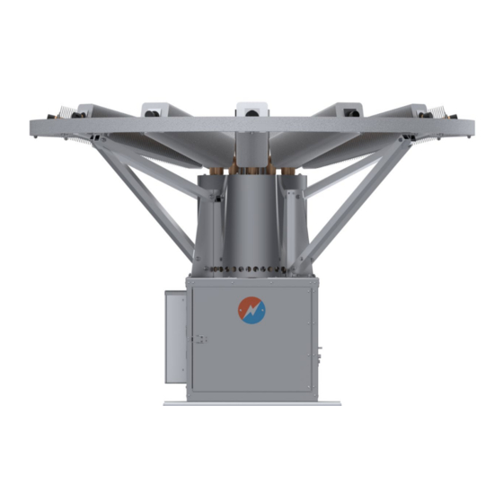
Page 54: Appendix A - Weight, Dimensions, And Electrical Specifications
APPENDIX A — WEIGHT, DIMENSIONS, AND ELECTRICAL SPECIFICATIONS Figure 29 shows the Model 8550 TEG in its normal operating configuration. Physical size data is listed below. Figure 29 – Model 8550-SD TEG Dimensions WEIGHT AND DIMENSIONS Diameter of Top 61 in... -
Page 55: Appendix B - Process Description
The operation of the TEG is controlled by the fuel pressure supplied to the burner. 05585 rev11 | Model 8550-SD Page 51 of 53... -
Page 56: Figure 31 - Gross Power Unit Electrical Output Characteristics At 20°C, Beginning Of Life (Without Power Conditioner)
Model 8550-SD TEG. Consult GPT for assistance with finding the best system to suit your application. The available power of a Model 8550-SD TEG is also a function of the amount of cooling supplied by the heat pipes, and this cooling is affected by both the ambient air temperature and the wind speed. -
Page 57: Appendix C - System Wiring Diagram
Global Power Technologies APPENDIX C — SYSTEM WIRING DIAGRAM APPENDIX C — SYSTEM WIRING DIAGRAM Figure 32 – Model 8550-SD TEG Wiring Diagram 05585 rev11 | Model 8550-SD Page 53 of 53... - Page 58 FORMS AND LOGS 8550 Thermoelectric Generator Start-Up Data Sheet Model #: Serial #: Fuel Type: Start-Up By: Date: Ambient Temperature: Ignition Fuel Pressure: Corrected Air Temperature: Operating Fuel Pressure: Wind Speed: Site Elevation Set Power at Corrected Temperature: Corrected Fuel Pressure for Elevation: POWER LEVELS Burner Fuel Time...
- Page 59 Model 8550-SD TEG Performance Log MODEL NO: SERIAL NO: FUEL TYPE: 05585 rev11...
- Page 60 Model 8550-SD TEG Performance Log MODEL NO: SERIAL NO: FUEL TYPE: 05585 rev11...
- Page 61 If <20°C (36°F), Detailed Inspection) Good *Hand temperature inspection of Model 8550-SD TEG heat pipes is done to check that the heat pipe is warm, up to 2 inches (50 mm) from the tip. If the inspection satisfies the hand inspection as per Section 3.5.1, the detailed inspection described in...
Need help?
Do you have a question about the 8550-SD and is the answer not in the manual?
Questions and answers