
Related Manuals for Global 1120


Summary of Contents for Global 1120
- Page 1 1120 THERMOELECTRIC GENERATOR CLASS I, DIVISION 2, GROUP D, T3 Operating Manual #16, 7875 - 57 th Street SE Calgary, Alberta Canada T2C 5K7 Main: +1 403 236 5556 Fax: +1 403 236 5575 www.globalte.com 22786 REV 9...
-
Page 3: Table Of Contents
3.10 1120 TEG Parts Lists ........ - Page 4 TABLE OF CONTENTS Appendix . . . . . . . . . . . . . . . . . . . . . . . . . . . . . . . . . . . . . . . . . . . . . . . . . . . . . . . . . . . .49 4.1 Gas Specifications .
- Page 5 Physical Description, 1120 TEG ........5...
- Page 7 MODEL 1120 HAZARDOUS AREA GENERATING SYSTEM DESIGNED FOR CLASS I, DIVISION 2, GROUP D T3 OPERATION SPECIFICATIONS Output Voltage Nominal 12-18 VDC 24-30 VDC Power Output 100 Watts Minimum Special Features Digital Panel Meter, LED, Voltage and Current Integral Blocking Diode Voltage Sensing Alarm with dry contacts Auto Shutoff Spark Ignition Auto Re-ignition Fuel Consumption Natural Gas: 8.8 m per day, (311 Sft per day) Propane: 11.4 L per day, (30 US gal per day) Inlet Fuel Supply Pressure Max 172 kPa (25 psi) Min 69 kPa (10 psi) Natural Gas Min 103 kPa (15 psi) Propane Dimensions Width 61 cm (24.0 in.) with electronics box closed 92 cm (36.0 in.) with electronics box open Depth 80 cm (31.6 in.)
-
Page 9: General
Thermoelectric Generator: A device that produces electrical power through the direct conver- sion of heat energy to electrical energy. Power Unit: The hermetically sealed portion of the generator that contains the thermoelectric materials and the cooling fins. TEG: A thermoelectric generator. Matched Load: A condition of load where: the load voltage of the generator is one-half of the open circuit voltage. the load resistance is equal to the internal resistance of the generator. Optimum Load: A condition of load where the power output of the generator is maximized. Precision Load: The precision resistor contained on the generator that provides the optimum load condition. The voltage across the resistor is defined as V and is used to analyze gener- ator electrical performance. Power Conditioner: A broad term used to describe an electronic device attached to the gen- erator output that converts, adjusts, limits or otherwise conditions power. Auto Shutoff: The 1120 generator is equipped with a thermocouple controlled solenoid valve that can be manually reset. In the event of extended flame failure the thermocouple output will be reduced sufficiently to release the solenoid and stop fuel gas flow to the burner. Converter: A specific electronic device attached between the generator and load that converts one level of DC voltage to another. Limiter: A specific electronic device attached across the generator output that limits the volt- age level. Global Power Technologies 1120 - Class I, Division 2, Group D, T3... - Page 10 (i) Hazardous concentrations of flammable gases or vapours exist continuously, intermittently, or periodically under normal operating conditions; or (ii) Hazardous concentrations of flammable gases or vapours may exist frequently because of repair or maintenance operation or because of leakage; or (iii) Equipment is operated or processes carried on of such nature that breakdown or faulty operation thereof could result in the release of hazardous concentrations of flammable gases or vapours and simultaneous failure of electrical equipment; Division 2, comprising Class I locations in which: Global Power Technologies 1120 - Class I, Division 2, Group D, T3...
-
Page 11: Theory Of Operation
If this junction is heated to a higher temperature than the other end of the wire, Figure1 TEG Design a voltage will exist across the cooler end. Further, electrical power will be delivered to a load placed in the circuit. This process will continue provided that the temperature difference is maintained. A TEG is a system which provides the means to maintain these required con- ditions. Figure 1 illustrates how this is accomplished in the model 1120 TEG. A thermocouple is formed by a P type and an N type thermoelectric element joined together electrically by a hot junction electrode. Adjacent thermocouples are joined together electrically by cold junction electrodes. Eighty thermocouples, each producing 84mV are connected in series so the power unit produc- es 120 Watts at 6.7 Volts and 18 Amperes. Global Power Technologies 1120 - Class I, Division 2, Group D, T3... -
Page 12: Physical Description
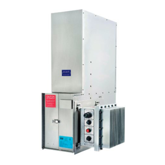
The burner operates at moderate pressures from 28 to 70 kPa (4 to 10 psi). The gas is expanded through an orifice and then flows through a venturi where it draws in air needed for combustion. The fuel flow is controlled by a pressure regulator and is adjusted by the operator to obtain the desired power output. In summary, the TEG produces electrical power when a temperature difference is maintained between the hot and cold junctions of the thermoelectric materials. The temperature difference, and therefore the amount of power produced, depends on the rate at which fuel is supplied to the burner. The operation of the TEG is simply the control of the fuel pressure to the burner which results in the desired power output. 1 .4 Physical Description Figure 2 shows the generator in its normal operating position. Global Power Technologies 1120 - Class I, Division 2, Group D, T3... -
Page 13: Figure 2 Physical Description, 1120 Teg
1120 TEG w/ Drip Cap 1120 TEG w/ Rain Shroud Figure 2 Physical Description Global Power Technologies 1120 - Class I, Division 2, Group D, T3... -
Page 14: Electrical Output Characteristics
1 .5 Electrical Output Characteristics Figure 3 shows the electrical output characteristics of the Model 1120 power unit, which gives the power, current and voltage as a function of the load resistance. The TEG will operate at any load condition from short circuit to open circuit. Observe that the power goes through a broad maximum between 0.3 and 0.5 ohms. Rated power (120 Watts) can be obtained only if the load resistance is within this range. The graph is useful in determining power, current and voltage at various customer load conditions. Refer to the graph and consider the following example: You are installing a Model 1120 TEG at a gas wellhead to cathodically protect the well-casing from corrosion. You have measured and determined your total ground bed resistance to be 1.0 ohm. Find 1.0 ohm on the horizontal axis. Read vertically until intersecting the power, current, and voltage curves. Read horizontally to the vertical axis to determine the values of power, current and volt- age. Which are 106 Watts, 10.2 Amps and 10.3 Volts. 1.6 Ambient Temperature Effects The electrical output of the TEG is dependent on ambient temperature as shown in Figure 4. Observe that the power decreases as ambient temperature increases. Statement of Rated Power The Power Unit produces 120 Watts when operated at an ambient temperature of 20ºC. -
Page 15: Figure 3 Electrical Output Characteristics
Figure 3 Power Unit Electrical Output Characteristics @ 20° Global Power Technologies 1120 - Class I, Division 2, Group D, T3... -
Page 16: Figure 4 Power Vs. Ambient Temperature
Figure 4 Gross Power from 1120 Power Unit Vs Ambient Temperature Global Power Technologies 1120 - Class I, Division 2, Group D, T3... -
Page 17: Fuel Consumption
Figure 5. Ensure that the TEG is mounted in accordance with following notes: The TEG must be mounted with the fin duct in a vertical position. The air flow through the cooling fins must not be obstructed. The TEG should be mounted at a height sufficient to prevent direct flooding or heavy snowfall from interfering with the flow of cooling or intake air. When the generator is installed near a building, field experience has shown that the best locations are on the roof or on the windward side, with a minimum distance of 3.0 meters (10 feet) from the building. Be sure that the TEG location relative to buildings and fuel containers are in accordance with local regulations. Global Power Technologies 1120 - Class I, Division 2, Group D, T3... -
Page 18: Mechanical Inspection
Check that all conduit connections are secure and the mountings are tight. Locate the fuel system assembly and ensure that all the connections are tight. Check that all hardware and mountings are secure and tighten as necessary. When the mechanical inspection is complete, proceed to electrical connection. Global Power Technologies 1120 - Class I, Division 2, Group D, T3... -
Page 19: Figure 6 Mechanical Inspection
• AIR INTAKE FLAME ARRESTORS © • FUEL SYSTEM '(g' © --- - I©' 7774 Rev5 1120 TEG w/ Drip Cap 1120 TEG w/ Rain Shroud Figure 6 Mechanical Inspection, Global Power Technologies 1120 - Class I, Division 2, Group D, T3... -
Page 20: Electrical Connection
3/8-16 bolts installed in the lid and swing the lid open. Terminal blocks have been factory installed for customer connection. TB2-2 is +24 Volts, TB2-3 is -24 Volts. The voltage sensing relay terminals are located on the Limiter Converter board mounted on the lid. Figure 7 Recommended Connections 1 .13 Fuel Supply Connection Although the TEG fuel regulator incorporates a liquid trap and 40-50 micron stainless steel filter, the generator system has been designed to operate on sales or instrument quality fuel. Due to site specific fuel characteristics, ensure that necessary pre-filtration has been installed prior to connection to TEG fuel lines. Global Power Technologies 1120 - Class I, Division 2, Group D, T3... -
Page 21: Start Up Preparation
The TEG is Equipped with a 1/4” NPT Male Input Connection . Remove the protecting plas- tic cap and connect the fuel line. Test all connections to ensure they are leak tight with leak detector. 1 .14 Start Up Preparation 1.14.1 Ensure that the fuel is turned off. 1.14.2 Reconnect the 2 Volt battery. Ensure that all electrical connections are secure. Install ionizing corrosion inhibitor on the floor of the electronics housing. 1.14.3 Close the electronics housing and install the twenty 3/8-16 bolts. The Customer must Tighten all Bolts to Establish Explosion Proof Seal of the assembly and provide weather proofing. Global Power Technologies 1120 - Class I, Division 2, Group D, T3... - Page 22 1.14.4 Test the ignitor system. While pushing the manual ignitor button, listen at the ignitor housing. A sharp snap should be heard as the ignitor discharges. If this is not audible, refer to Trouble Shooting (section 3.9) for set up of ignitor system and correct. 1.14.5 Proceed to Section 2, Operation. Global Power Technologies 1120 - Class I, Division 2, Group D, T3...
-
Page 23: Operation
2.1.6 Fuel Input Rating The fuel input rating is the maximum fuel energy input rate of the TEG. 2.1.7 Inlet Pressure The inlet pressure is the maximum permitted fuel supply pressure range. 2.1.8 Burner Fuel Pressure The burner fuel pressure as stated is the range of burner fuel pressure the TEG is designed to operate when using fuel gas meeting GPT’s fuel specification requirements. Burner fuel pressure is set using the fuel system regulator. Global Power Technologies 1120 - Class I, Division 2, Group D, T3... -
Page 24: Figure 9 Change In Fuel Pressure Vs Elevation
2.1.9 Factory Settings The power output at ambient temperature, voltage across the precision load, and burner fuel pressure that were measured during factory performance test at elevation of the factory are recorded as factory settings. This information is provided for reference only because the fuel pressure is adjusted to obtain the desired power at customer site. Figure 9 Change in Fuel Pressure Vs Elevation Global Power Technologies 1120 - Class I, Division 2, Group D, T3... -
Page 25: Start-Up Data Sheets
Start-up Data Sheets are provided at the back of this manual to assist you in setting up the TEG properly. During set up you will be asked to record data on these sheets so keep them available. It is recommended that a Data Sheet be used each time the TEG is started. They are valuable for future reference. If additional sheets are needed they can be duplicated. 2 .3 Starting Generator Perform the following steps (see Figure 10): 2.3.1 Turn on fuel. Loosen the lock nut on the fuel regulator. 2.3.2 If required, correct the factory set fuel pressure for the elevation as per Figure 9, Change in Fuel Pressure Vs . Elevation . 2.3.3 Adjust the air shutters to slightly fuel rich from the factory set position. Note that the air shutters should always be adjusted equally in small increments. 2.3.4 Set the “Power Switch” to set up position. 2.3.5 Set the “Output Voltage Adjust” to middle position. Global Power Technologies 1120 - Class I, Division 2, Group D, T3... -
Page 26: Heat Up To Rated Power
If V is greater than 6.5 volts, the fuel pressure is set for more than rated power. Reduce the fuel pressure by 9.8 kPa (1.4 psi) at this time, see Figure10 and Figure 13. WARNING: To prevent damage to the TEG do not allow the V to exceed 7.1 volts at ambient temperatures above 24ºC (75ºF). 2 .6 Versus Power the voltage across the precision load, is a measure of power. The value of the precision load (0.387 ohms) is selected to provide the optimum load condition for the TEG. Global Power Technologies 1120 - Class I, Division 2, Group D, T3... -
Page 27: Determining Required V Set
The power is 120 watts. Locate 120 watts on the horizontal axis. Read vertically until intersecting the curve. Read horizontally to the vertical axis to determine V Which is 6.8 volts. 2 .7 Determining Required V This heat up period is the ideal time to determine the V is based on set up power as follows: SET UP POWER from Figure 4 from Figure 12 Set up power is found by adjusting the desired power for ambient temperature. V is deter- mined from set up power as shown in Figure 12. Estimate the maximum ambient temperature expected at the side and record on the start up data sheet as Item 3. Measure or estimate the present ambient temperature and record as Item 4. If rated power or maximum allowable power is desired: Use the information in Figure 4 and the procedures in section 1.7 to determine the cor- responding set up power and record as Item 5. Use Figure 12 to determine the related V and record as Item 6. Global Power Technologies 1120 - Class I, Division 2, Group D, T3... -
Page 28: Fuel And Air Adjustment
Figure 12 V Vs Set up Power If less than rated power is desired: Determine the desired power output. Determine the corresponding set up power by adding 0.3 watts to the desired power for each ºC difference between the present and maximum ambient temperatures. Refer to Figure 12 to determine the related V and record as Item 6. 2 .8 Fuel & Air Adjustment After the TEG has been operating for one hour, V should not be changing with time. The readings on the start up data sheet at 40 and 60 minutes should not differ by more than 0.2 volts. When you are satisfied that V is not changing with time, compare the measured value of V with the required V , Item 6. Proceed with air shutter adjustments to optimize the burn- er first (section 2.9) then adjust the fuel pressure as required (section 2.10). Global Power Technologies 1120 - Class I, Division 2, Group D, T3... -
Page 29: Air Shutter Adjustment
In both cases fuel is being wasted. When the air shutter is at its optimum setting (neither of above) the TEG is operating at maximum efficiency. NOTE: If available a combustion analyzer will facilitate rapid air shutter optimizing as you need not wait for V to change. Figure 13 shows change in V as a function of air shutter settings. Observe that V decreases more rapidly on the fuel rich side than on the air rich side. For this reason a fuel rich operation is to be avoided. Make initial adjustments of air shutters towards the fuel rich side by decreasing the air holes. Global Power Technologies 1120 - Class I, Division 2, Group D, T3... -
Page 30: Fuel Pressure Adjustment
Suppose the measured V is 6.5 volts, but 6.7 volts or a change of +0.2 volts is required. Locate the ±0.2 volts on the vertical axis and read horizontally until intersecting the curve. Read vertically down to the horizontal axis and find the required change in fuel pressure. Which is 5.5 kPa (0.8 psi). You must increase the fuel pressure by 5.5 kPa or 0.8 psi. Suppose the measured V is 6.8 volts and that 6.5 volts or a change of -0.3 volts is required. Locate -0.3 on the vertical axis and read horizontally until intersecting the curve. Read vertically down to the horizontal axis and find the required change in fuel pressure. Which is -8.3 kPa (-1.2 psi). You must decrease the fuel pressure by 8.3 kPa or 1.2 psi. 2.10.1 Use the following procedures to make the adjustment in fuel pressure: Global Power Technologies 1120 - Class I, Division 2, Group D, T3... - Page 31 Figure 14 Fuel Pressure Vs V Record V after a minimum of one hour of operation as Item 7. Determine the required change in V by subtracting Item 7 from Item 6 and record as Item 8. Record the fuel pressure as Item 9. Determine the required change in fuel pressure from Figure 14 and record as Item 10. Determine the new fuel pressure by adding Item 10 to Item 9 and record as Item 11. EXAMPLE: Item 9 = 37.9 kPa (5.5 psi) Item 10 = 2.1 kPa (0.3 psi) New Fuel Pressure = 35.8 kPa (5.2 psi) Adjust the fuel pressure to the value in Item 11. Close the cabinet doors and record the time. Global Power Technologies 1120 - Class I, Division 2, Group D, T3...
-
Page 32: Applying Customer Load
When the measured and required values of V are in agreement, the TEG is ready to switch to operation mode. 2 .11 Applying Customer Load The TEG is now operating at the required power output. If this is a single TEG system, it is ready to connect to the customer load. If there are multiple TEGs ensure that all units are ready before proceeding. If station batteries are present, measure and record their voltage. Batteries should be fully charged; if they are too deeply discharged, the 1120 TEG will not charge the station battery. Set power switch to “Run” position, see Figure 10. The TEG “normal” light should come on. Adjust the voltage control to the desired operating voltage plus 0.7 volts using the Output Voltage Adjust dial on the electronics box and the reading on digital panel meter. If a multiple TEG system is in use, ensure that all outputs are equal. Note: The TEG incorporates a protective series diode. The output voltage will drop 0.7 Volts from the no load to loaded condition. Push the red “Meter Select” button to read the current. Connect the customer load via disconnects mentioned in Electrical Connection section 1.12. The TEG “Normal” light should remain as a steady glow, if the lamp dims or the output voltage drops significantly, the TEG is being overloaded. Ensure that the load is no more than 100 watts at 24-30 volts. In multiple generator systems ensure that all outputs are set the same. Global Power Technologies 1120 - Class I, Division 2, Group D, T3... -
Page 33: Service
SERVICE 3 .1 1120 TEG This section contains service information and theory of operation on the 1120 generator system only. If the system contains any options, they are described in the Special Options section. The 1120 Generator can be broken down into several subsystems consisting of the following (see Figure 15): • Power Unit Assembly • Burner Assembly • Igniter Housing Assembly • Fuel System Assembly • Conduit Assembly Electronics • Electronics Assembly Figure 15 TEG Subsystems, 1120 w/ Drip Cap Global Power Technologies 1120 - Class I, Division 2, Group D, T3... -
Page 34: Figure 16 Power Unit
Figure 15 TEG Subsystems, 1120 w/ Rain Shroud Figure 16 Power Unit Global Power Technologies 1120 - Class I, Division 2, Group D, T3... -
Page 35: Power Unit
3 .3 Burner Assembly: See Figure 25 The burner assembly consists of the burner components, the heat exchanger, and flame arres- tors, air intake and exhaust . This assembly performs several functions. The orifice introduces fuel at a predetermined pressure to the burner. This fuel flows through the venturi tube and the venturi effect causes air to be drawn in through the intake flame arres- tors. The air shutters regulate the combustion air quantity. Thus fuel and air are mixed in the venturi tube and passed through the burner screen to the back of the combustion chamber, where it is ignited and burned to produce the operating temperature required. See Figure 1, section 1.3. Global Power Technologies 1120 - Class I, Division 2, Group D, T3... -
Page 36: Fuel Assembly
14 kPa (2 psi). This switch on closing applies 2 VDC and power to the ignition system dis- cussed above. This feature gives auto ignition at start up and a short term auto re-ignition in the event of a flame out, due to blow out, short term loss of gas, or short term severe hazard condition. The fuel is next fed to the flexible fuel line and then to the orifice. The flexible fuel line is stan- dard, however the orifice is unique to the type of fuel used, natural gas or propane. 3 .5 Igniter Housing Assembly: See Figure 28 . The ignitor housing assembly consists of a junction box housing, the associated fittings and the high voltage ignitor module. Also it contains the ignitor electrode assembly, the interconnect cable and the mounting connector. Global Power Technologies 1120 - Class I, Division 2, Group D, T3... -
Page 37: Conduit Assembly
3.7.1 Electronic Housing: This box has been designed to meet the requirements of Class I, Division 2, hazardous areas. It also performs as a heat sink capable of dissipating the full output power of the TEG when in a set up or no load condition. 3.7.2 Precision Load: Two 0.75 ohm, 50 watt resistors connected in parallel (resulting in 0.375 ohm) as well as their associated wiring, which when switched to the power unit, give us a precision load resistance of 0.387 ohm (approximately), provide the optimum load condition for the TEG. This precision load is used for adjusting the TEG and eval- uating its performance. A load voltage of 6.87 volts would give 120 watts from the TEG. Global Power Technologies 1120 - Class I, Division 2, Group D, T3... -
Page 38: Figure 18 Schematic Diagram, 1120 Teg (Sheet 1 Of 2)
Figure 18 Schematic Diagram, 1120 TEG (sheet 1 of 2) Global Power Technologies 1120 - Class I, Division 2, Group D, T3... -
Page 39: Figure 19 Schematic Diagram, 1120 Teg (Sheet 2 Of 2)
Figure 19 Schematic Diagram, 1120 TEG (Sheet 2 of 2) Global Power Technologies 1120 - Class I, Division 2, Group D, T3... -
Page 40: Figure 20 Electronics Diagram, 1120 Teg
Figure 20 Electronics Diagram, 1120 TEG Global Power Technologies 1120 - Class I, Division 2, Group D, T3... - Page 41 The input current is limited through the shunt mounted to the main PCB. The LM2908 Op-Amps drive transistor 2N4401 which increases the current limit sense voltage drop at pin 13 of the TL497 as it turns on. The 20K trim pot is used to set the gain of the OP-AMP to limit the current at 15 AMPs. This is factory set and should not be adjusted by field personnel. 3.7.5 Voltage Sensing Relay Circuit (VSR): Refer to Figure 19. The VSR circuit uses a LM311 voltage comparator to operate the relay K1. The 2.5 Volt level created by the LM285Z 2.5 voltage reference is used as one input while the output from the tap of the 10K trim pot is used as the other. The LM317T is configured as a 10.0 volt regulator to provide a stable voltage for the relay and comparator to operate with either a 12 or 24V output voltage. The 10K trim pot is set so that the relay is energized for normal opera- tion, and de-energizes for an alarm. The relay contacts are brought out to the edge of the main PCB shown in Figure 30. Global Power Technologies 1120 - Class I, Division 2, Group D, T3...
-
Page 42: Service
3 .8 Service 3.8.1 On Site Visits Drain the sediment bowl of the fuel regulator by opening the drain cock. Read and record the fuel pressure and the output of TEG pressure regulator. If a master fuel gauge is present, record this pressure. Notice if the normal light is lit. The lamp should glow steady (generator running). If the lamp is out, check and replace the bulb. If the lamp is flashing, overload condition exists. Trouble shoot the system. Read and record the output voltage and current. Visually check for loose components or hardware. Tighten any loose hardware and connections. NOTE: No adjustment should be made to any devices, unless malfunctions were found and corrected. Global Power Technologies 1120 - Class I, Division 2, Group D, T3... -
Page 43: Field Troubleshooting
Whenever major work or repairs are required other than that called out in field troubleshooting: The generator or electronics assembly must be removed to a safe area. Or: The area in which the generator is being Figure 22 Fuel Regulator used must be rendered safe in accordance with all regulations governing the operations area. 3.9.1 Changing the Fuel Filter (Figure 20, Figure 21) Global Power Technologies 1120 - Class I, Division 2, Group D, T3... - Page 44 If it is necessary to remove the fuel filter, the complete fuel assembly must be removed. Shut off fuel, disconnect the fuel input at point A. Disconnect the flexible fuel line at point B. Remove the two nuts holding the regulator to the mounting bracket (point D). Remove the four socket cap screws from the bottom of the regulator. Remove the bot- tom, complete with the rubber gasket (see Figure 22). Remove and inspect the filter, clean or replace as required. Re-assemble in reverse order. Ensure that all joints are leak checked prior to starting generator. Global Power Technologies 1120 - Class I, Division 2, Group D, T3...
- Page 45 If spark is present, check the pressure switch and pressure switch wiring. If no spark is present check if electrode is gapped. Check the battery. Replace if necessary. Replace the high voltage ignition module. If ignition occurs and unit continues to fire, but will not stabilize (sustained combustion) note the position of the air shutters and Burner does not remain ignited. adjust for sustained ignition. Reset the air shutters when the unit warms up. Burner does not remain ignit- Replace thermocouple. ed when shut off valve button is released Replace shut off valve. Incorrect fuel adjustment, see section 2.10. Incorrect air adjustment, see section 2.9. Output power or voltage low (TEG in Set Up position). Dirty fuel filter, orifice, or intake flame arrestors. Protective limiter faulty. Output power or voltage high. Incorrect fuel adjustment, see section 2.10. If any problems are encountered with the power conditioner, the Output power or voltage low (TEG generator or electronics assembly should be removed to a safe in Operate position). area. Global Power Technologies 1120 - Class I, Division 2, Group D, T3...
- Page 46 Possible short circuit condition, disconnect the load. If the lamp lights OK and the voltmeter is OK then trouble shoot the load. TEG Normal light is out, voltmeter is out, TEG is If the lamp does not light and the voltmeter does running not come on switch to “Set Up”. If the voltmeter reads 6 Volts or more there is probably an internal short in the electronics housing. Trouble shoot the electronics assembly. Global Power Technologies 1120 - Class I, Division 2, Group D, T3...
-
Page 47: 1120 Teg Parts Lists
2275 Drip Cap Assy 2446 Burner Assy 20954 Screw, Mach, P-H-P, 1/4-20 X 5/8, 316 SS 7028 Cabinet Top Assy 20828 Thermocouple, 24”, K16RA-24, Soldered 57210 Heat Shield, 1120 Meter 3322 Cover, Digital Panel Meter A10 7336 Bezel, Digital Panel Meter A11 29606 Screw, Mach, P-H-P, 6-32 X 3/8, 316 SS A12 2405 Orifice Assy, #7, Propane 2406 Orifice Assy, #8, Natural Gas A13 2394 Washer, Disc Spring, #8 SS Global Power Technologies 1120 - Class I, Division 2, Group D, T3... - Page 48 29603 Screw, Mach, P-H-P, 6-32 X 5/8, 316 SS A15 2460 Air Shutter, Teflon A16 2311 Ignitor Housing Assy A17 22383 Fuel System Assy, W/CF Regulator 20955 Screw, Hex, HD, 1/4-20 X 3 1/2”, 316 SS 22024 Washer, Lock, 1/4, 316 SS 20952 Nut, Hex, 1/4-20, 316 SS A18 21773 Cabinet Assy A19 5286 Fuel Line Kit A20 2218 Leg, Left 2219 Leg, Right Global Power Technologies 1120 - Class I, Division 2, Group D, T3...
-
Page 49: Ignitor Details
Screw, Mach. Hex-HD, 1/4-20 x 3/8, 316 SS A31 24497 Screw, Mach, P-H-P, 8-32 X 1/4, 316 SS A32 23811 Washer, Lock. Spring, #8, 316 SS A33 22024 Washer, Lock. Spring, 1/4, 316 SS A34 20952 Nut, Hex, 1/4-20, 316 SS A35 2339 Fin Duct, Lower A36 8905 Power Unit A37 7625 Conduit Assy, Power Unit A38 2032 Electrode Assy, Spark Ignition A39 6362 Connector, 3/16-1/8, Nylon, NY-300-1-2 Global Power Technologies 1120 - Class I, Division 2, Group D, T3... -
Page 50: Burner Parts List
Description 2278 Burner Back Assy 2301 Insulation Support 701 Spacer, Insulation 693 Screen Holder 873 Screen, Burner 694 Insert Ring, Burner 2302 Insulation Block 2401 Venturi Tube Holder 971 Venturi B10 479 Screw, Set, Soc. HD, 6-32 X 1/8, SS B11 2389 Burner Cover Assy B12 2454 Flame Arrestor Assy, Air Intake Global Power Technologies 1120 - Class I, Division 2, Group D, T3... - Page 51 Figure 25 Burner Parts Item Part No . Description B13 609 Nut, Hex, 10-32, SS B14 469 Washer, Int. Lock, #10, SS B15 2415 Flame Arrestor Assy, Exhaust B16 5241 Flame Arrestor Housing, Upper B17 2452 Exhaust Stack B18 2413 Screw, Hex HD, 1/4-20 X 1.00, SS B19 541 Washer, Lock, Spring, 1/4, SS Global Power Technologies 1120 - Class I, Division 2, Group D, T3...
-
Page 52: Fuel System Parts List
2350 Gauge, Pressure, 0-15 PSI 176 Valve, Shut off, BASCO H19-TA3 1429 Pressure Switch, H0BBS 78628 20071 Elbow, 1/4 NPT X 1/4 Tube, SS 5286 *Fuel Line Kit 20828 *Thermocouple, 24”, K16RA-24, Soldered (order separately) C10 2356 Elbow, Street, 1/4 NPT, SS C11 2358 Nipple, 1/4 NPT X 3”, SS C12 2360 Adaptor, 1/4 NPT, SS C13 20067 Vent Tube Assy, 1120 C14 22363 *Fuel Filter Kit, Fisher 67 CFR (not shown) *NOTE: Parts not included if ordering entire igniter housing, must be ordered separately. Global Power Technologies 1120 - Class I, Division 2, Group D, T3... -
Page 53: Conduit Assembly Parts List
Part No . Description 5216 Junction Box, 4 Outlet 2428 Connector, Strain Relief, 1/2 NPT 2163 Connector, 90 , 3/8 Conduit, 1/2 NPT 5222 Plug, Close Up, 1/2 NPT, CUP-1 2168 Conduit, Liquid Tight Flex, 3/8” 22” 2168 Conduit, Liquid Tight Flex, 3/8” 10” 20156 Barrier Gland, 3/4 NPT 20155 Reducer Bushing, 3/4” X 1/2”, ALUM 2456 Cable Assembly 6372 Ignitor Cable, Conduit Assy D10 51084 Digital Panel Meter Assy, 1120 Global Power Technologies 1120 - Class I, Division 2, Group D, T3... -
Page 54: Ignitor Housing Assembly Parts List
Nipple, 1/2, Close, SS 2340 Holder Assy, Ignitor 5247 Junction Box, 1 1/4 NPT, Class I, Group D 60307 Ignitor Board Assy 6362 *Connector, 3/16-1/8, Nylon, NY-300-1-2 2032 *Electrode Assy, Spark Ignitor 21650 Nut, Hex, 6-32, SS, 1/4” Across Flats E10 Ground Cable, SI 5205 Female Disconnect, DNF18-250Fib 137 Wire, 20AWG,Green, 6” 204 Terminal, Ring, 1/4 RED, PNF18-14R E11 2379 Reducer, 1 1/4 X 3/4 NPT, ALUM E12 2376 Connector, 90 , M-F, 3/4 NPT, ALUM *NOTE: Parts not included if ordering entire ignitor housing, must be ordered separately. Global Power Technologies 1120 - Class I, Division 2, Group D, T3... -
Page 55: Electronics Box L/C Parts List
Figure 29 Electronic Box Item Part No . Description 2373 Switch, Push Button, Illuminated 27019 Battery, 2V, 2.5 AH, D Size 6527 Shunt, 10A, 50mV, Holloway Type SW w/Base 2282 Control Board, Spark Ignitor 2418 Terminal Block, 7 Position 7329 PCB, Voltmeter Control, LED 6714 Terminal Block, 3 Pole, Heavy Duty 2374 Actuator, Potentiometer Adjust 2160 Switch, Push Button F10 7810 Switch, CAM, BACO PR 26 225 Global Power Technologies 1120 - Class I, Division 2, Group D, T3... -
Page 56: Electronics Box Lid L/C Parts List
Electronics box Lid L/C Parts List Figure 30 Electronic Box Lid Item Part No . Description F11 5317 PCB Assy, Limiter Converter, 220W F12 114 Resistor, 0.75 OHM, 50W, 1% F13 2183 Resistor, 2.0 OHM, 50W, 1% F14 5350 Heat Sink, Limiter Converter F15 6181 Potentiometer, 1 turn 2 KOhm, 2 Watt F16 29529 LED, Green, BA9S-G, 28 Volt Global Power Technologies 1120 - Class I, Division 2, Group D, T3... - Page 57 Natural Gas: 37 MJ/Sm (1000 BTU/cu.ft.) Propane/LPG: 93 MJ/Sm (2500 BTU/cu.ft.) Butane: 108 MJ/Sm (2900 BTU/cu.ft.) Shall not exceed 60ºC (140ºF) in temperature. Notes: (1) - For gaseous fuels outside of these specifications, please contact Global Power Technologies (GPT). (2) - Sm = Standard cubic meter of gas at 101.325 kPa at 20ºC (NIST). Global Power Technologies 1120 - Class I, Division 2, Group D, T3...
- Page 58 Air Shutter Adjustment Air Shutter Adjustment Air Shutter Direction Air Shutter Direction Time Time of air shutter adjustment of air shutter adjustment New V New V measured 10 minutes afte measured 10 minutes afte air shutter adjustment air shutter adjustment measured (final before applying measured (final before applying load) load) Notes: Notes: Global Power Technologies 1120 - Class I, Division 2, Group D, T3...
- Page 59 Air Shutter Adjustment Air Shutter Adjustment Air Shutter Direction Air Shutter Direction Time Time of air shutter adjustment of air shutter adjustment New V New V measured 10 minutes afte measured 10 minutes afte air shutter adjustment air shutter adjustment measured (final before applying measured (final before applying load) load) Notes: Notes: Global Power Technologies 1120 - Class I, Division 2, Group D, T3...
- Page 60 Global Power Technologies 1120 - Class I, Division 2, Group D, T3...
- Page 61 Global Power Technologies 1120 - Class I, Division 2, Group D, T3...
Need help?
Do you have a question about the 1120 and is the answer not in the manual?
Questions and answers