Advertisement
Available languages
Available languages
INSTALLATION MANUAL
Model:TCB-PSMT1E
Multi Tenant Kit
Precautions for safety
• Read these "Precautions for safety" carefully before installation work.
• The precautions described below include important items regarding safety. Observe them without fail. Understand the following details (indications and symbols) before reading the body text, and follow the
Installation Manual.
The meanings of indications
Text set off in this manner indicates that failure to adhere to
WARNING
the directions in the warning could result in serious bodily
harm or loss of life if the product is handled improperly.
Text set off in this manner indicates that failure to adhere to
the directions in the caution could result in serious bodily
CAUTION
injury or damage to property if the product is handled
improperly.
WARNING
WARNING
• Only a qualified installer or qualified service person is allowed to do installation work.
If installation is carried out by an unqualified individual, fire or electric shock may result.
• Perform installation work reliably according to this Installation Manual.
Incomplete installation may cause electric shock, fire or abnormal operation.
• Electrical work must be performed by a qualified installer or qualified service person in accordance with this Installation Manual. Appliance shall be installed in accordance with national wiring
regulations. Inappropriate work may result in electric shock or fire.
• Connect earth wire. (grounding work) Incomplete grounding cause an electric shock.
• Before obtaining access to terminals, all supply circuits must be disconnected.
• Install in a location where will not be touched by the general public.
• To Disconnect the Appliance from Main Power Supply.
This appliance must be connected to the main power supply by means of a switch with a contact separation of at least 3 mm.
• Connect the specified wires firmly and clamp them securely so that external force applied to the wires does not affect the connector pins.
Improper wire connection or clamping may result in fire or malfunction.
• Do not disassemble, modify, repair or move the product yourself.
Doing so may cause fire, electric shock, injury or water leaks.
• Ask a qualified installer or qualified service person to do any repairs or to move the product.
REQUIREMENT
• When the indoor unit with Multi Tenant Kit is turned on (breaker is ON) or turned off (breaker is OFF), the system will stop; however, it will restart after a short period.
• As there is a risk of electric shock during maintenance, turn off the power of the step-down transformer, as well as that of the indoor and outdoors units.
Accessories
No.
Parts name
1
Multi Tenant Kit
2
Power cable
3
Indoor unit connection cable (A)
4
Indoor unit connection cable (B)
5
Screws
6
Wire joint
7
Installation Manual
Applications and Functions
■
When the tenant power supply (indoor unit power supply) is turned off, this kit converts the input voltage (24 V AC) to a DC voltage and supplies a low voltage
to the indoor unit.
Furthermore, it transmits a signal to notify that the indoor unit power supply has been turned off.
The LCD of the wired remote controller turns off and becomes inoperable.
Applicable indoor units
4-way Air Cassette Type, Concealed Duct Standard Type, Slim Duct Type, Under Ceiling Type, Console Type,
High Wall Type, Concealed Duct High Static Pressure Type, Floor Standing Type, Floor Standing Cabinet Type,
Floor Standing Concealed Type
CAUTION
Install Slim Duct Type and Concealed Duct High Static Pressure Type (4 series) so that there is gravitational drainage.
(For details on gravitational drainage, refer to the installation manual of the indoor unit.)
Using a drain pump will cause a water leak.
Installation location
Install the Multi Tenant Kit within the range that the supplied indoor unit connection cable will reach (within approximately 2 m).
The Multi Tenant Kit cannot be mounted to the indoor unit.
Install the Multi Tenant Kit in a location where service space can be provided.
Installation in the following locations is not possible.
• Location where combustible gas may leak.
• Location subject to direct sunlight.
• Location that becomes very hot and humid. (Use at an ambient temperature of 40°C or less.)
• Very dusty location
• Location near a kitchen, bathroom, or factory equipment.
For other prohibited locations, refer to the installation manual for the indoor unit.
• After completion of installation, perform test run to check for any problems.
Explain method of use and maintenance to the customer by following the descriptions in the manual.
Ask customer to keep this manual at accessible place for future reference.
Q'ty
Remarks
1
1
For power supply: 3 - cores with earth wire
1
Indoor communication cable: 6-pin
1
Indoor communication cable: 5-pin
4
For installing the Multi Tenant Kit
2
For power cable connection
3
Must be handed over to the customer.
CB14800701(EN)
Installation procedure
Use the four supplied screws to install the Multi Tenant Kit in a location with sufficient strength so that there is no risk of it falling.
External view
Approx.1800
Wiring diagram
Power supply
220-240
, 50 Hz
Power supply
220-240
, 50 Hz
Power supply
220-240
, 50 Hz
• The above wiring diagram shows the wiring for the Super Heat Recovery Multi (SHRM) specifications. For SMMS series, omit the flow selector unit part.
• For Super Heat Recovery Multi (SHRM), use a separate power supply that is shared with Multi Tenant Kit for the power supply of the flow selector unit.
• Install the flow selector unit and step-down transformer in a machine room or shared spaced away from tenants.
• Install the circuit breaker in the AC24V power supply line.
• Locally procure a 24 V AC power supply power cable and step-down transformer that meet the following specifications.
Power cable specifications
Step-down transformer specifications
200
6 - Ø5.5 mounting hole
Approx.1800
22
78
78
22
Multi Tenant Kit
Step-down
Circuit breaker
Transformer
(Field supply)
(Field supply)
TB1
24
, 50 Hz
1
2
BLACK
1
CN3
2
WHITE
(RED)
3
Circuit breaker
Indoor unit
(Field supply)
RED
1
WHITE
2
3
CN67
(BLACK)
Flow selector unit
Circuit breaker
CN01
(Field supply)
(RED)
1
2
3
2
3 - cores cabtire cable with earth wire, 1.25 - 2.0 mm
Transformer (basic insulation specification) compliant with EN61558-1 / EN61558-2-6
Input voltage: 220-240 V AC, Output voltage: 24 V AC ±10%, 50 Hz, Load current: Max. 2.0 A
Unit: mm
Plate thickness: 0.7 mm
64.1
1
DC5V
2
DC13V
P.C.Board
3
COM
CN1
T6TOS-P930A
(WHITE)
CN2
CN4
(WHITE)
(YELLOW)
1
2 3
4 5
6
1
2 3
4
5
6
(OPTION)
6
3
1
1
2
3
4
5
6
2
CN61
CN50
3
(YELLOW)
(WHITE)
4
P.C.Board
5
1
2 3
4
5
CN81
(BLACK)
5
1
2
3 4
5
CN02
(GREEN)
P.C.Board
compliant with 60227 IEC 52
CB14800701(EN)
Advertisement
Table of Contents

Related Manuals for Toshiba TCB-PSMT1E


Summary of Contents for Toshiba TCB-PSMT1E
- Page 1 INSTALLATION MANUAL Use the four supplied screws to install the Multi Tenant Kit in a location with sufficient strength so that there is no risk of it falling. External view Model:TCB-PSMT1E Multi Tenant Kit Unit: mm Plate thickness: 0.7 mm Precautions for safety •...
-
Page 2: Wiring Method
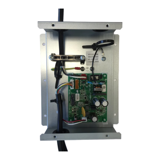
Wiring method Lite-Vision plus remote controller (RBC-AMS51E*) 1. Remove the four screws from the electrical parts box of Multi Tenant Kit and then remove the cover. 2. Attach 3-mm round terminals to the 24 V AC power supply cable and then connect the cable to the TB1 terminal. ∧... -
Page 3: Manuel D'installation
Méthode d’installation Manuel d’installation Utilisez les quatre vis fournis pour installer le kit multi locataire dans un endroit suffisamment solide pour qu'il ne tombe pas. Vue extérieure Model:TCB-PSMT1E Kit multi locataire Unité : mm Épaisseur de la plaque: 0,7 mm Précautions relatives à... -
Page 4: Méthode De Câblage
Méthode de câblage Télécommande Lite-Vision plus (RBC-AMS51E*) 1. Retirez les quatre vis du boîtier électrique du kit multi locataire puis retirez le couvercle. 2. Connectez les bornes rondes de 3 mm au câble d'alimentation 24 V CA puis connectez le câble à la borne TB1. 3. -
Page 5: Manuale D'installazione
Procedura d’installazione Manuale d’installazione Il Kit multi-utente deve essere installato con le quattro viti fornite in dotazione in un punto sufficientemente solido da impedirne la caduta. Vista esterna Model:TCB-PSMT1E Kit multi-utente Unità: mm Spessore della piastra: 0,7 mm Precauzioni per la sicurezza •... -
Page 6: Modalità Di Collegamento
Modalità di collegamento Telecomando Lite-Vision plus (RBC-AMS51E*) 1. Rimuovere le quattro viti dalla scatola dei componenti elettrici del Kit multi-utente per rimuovere il coperchio. 2. Installare dei capicorda da 3 mm sul cavo di alimentazione da 24 Vca e collegarlo al morsetto TB1. ∧...
Need help?
Do you have a question about the TCB-PSMT1E and is the answer not in the manual?
Questions and answers