
Subscribe to Our Youtube Channel
Related Manuals for ADLINK Technology NEON-1000-MDX Series


Summary of Contents for ADLINK Technology NEON-1000-MDX Series
- Page 1 NEON-1000-MDX Series AI Smart Camera User’s Manual Manual Rev.: Revision Date: August 26, 2020 Part No: 50-1Z331-1000 Leading EDGE COMPUTING...
- Page 2 Leading EDGE COMPUTING Revision History Revision Release Date Description of Change(s) 2020-08-26 Initial release Revision History...
-
Page 3: Preface
NEON-1000-MDX Preface Copyright © 2020 ADLINK Technology, Inc. This document contains proprietary information protected by copy- right. All rights are reserved. No part of this manual may be repro- duced by any mechanical, electronic, or other means in any form without prior written permission of the manufacturer. - Page 4 Leading EDGE COMPUTING Conventions Take note of the following conventions used throughout this manual to make sure that users perform certain tasks and instructions properly. Additional information, aids, and tips that help users perform tasks. NOTE: NOTE: Information to prevent minor physical injury, component dam- age, data loss, and/or program corruption when trying to com- plete a task.
-
Page 5: Table Of Contents
NEON-1000-MDX Table of Contents Revision History..............ii Preface ..................iii List of Figures ............... vii List of Tables................ix 1 Introduction ................ 1 Overview................1 Features................2 General Specifications............3 Mechanical Dimensions............5 1.4.1 Camera Dimensions ........... 5 1.4.2 USB Type-C Screw Lock Location and Dimensions .. 5 1.4.3 LED Light Mounting Thread........ - Page 6 Leading EDGE COMPUTING Using the Basler pylon Utility ..........22 3.6.1 Capturing Images with pylon ........22 3.6.2 Modifying Image Sensor Settings with pylon .... 24 3.6.3 Using APIs to Modify Image Sensor Settings ... 32 Important Safety Instructions..........33 Consignes de Sécurité...
-
Page 7: List Of Figures
NEON-1000-MDX List of Figures Figure 2-1: NEON-1000-MDX Orientation ......... 7 Figure 2-2: Bottom Side I/O and Connectors ........8 Figure 2-3: D-sub I/O Connector............9 Figure 2-4: Top Side I/O and Connectors ........11 Figure 2-5: Front Side I/O and Connectors ........12 Figure 3-1: NEON-1000-MDX Mounting Holes ........ - Page 8 Leading EDGE COMPUTING This page is intentionally left blank. viii List of Figures...
-
Page 9: List Of Tables
NEON-1000-MDX List of Tables Table 1-1: NEON-1000-MDX Model and Sensor Specifications . 1 Table 2-1: Bottom Side I/O and Connectors........ 8 Table 2-2: D-sub I/O Connector Pin Definitions......9 Table 2-3: D-sub I/O Connector Specifications ......10 Table 2-4: Top Side I/O and Connectors ........11 Table 2-5: Front Side I/O and Connectors......... - Page 10 Leading EDGE COMPUTING This page is intentionally left blank. List of Tables...
-
Page 11: Introduction
NEON-1000-MDX Introduction 1.1 Overview The NEON-1000-MDX series is an open camera platform ® ® equipped with an Intel Atom E3930 processor and Intel Movid- ius™ Myriad™ X MA2485 VPU that provide image capture and inferencing capabilities. The NEON-1000-MDX is designed for deep learning inference and other vision applications that require a compact device. -
Page 12: Features
Leading EDGE COMPUTING 1.2 Features All-in-one design reduces space requirements and mini- mizes cabling, installation, and maintenance effort ® ® Intel Atom E3930 processor, Intel Movidius™ Myriad™ X MA2485 VPU, image sensor, and FPGA-based I/O integra- tion designed for the image processing vertical market ... -
Page 13: General Specifications
NEON-1000-MDX 1.3 General Specifications Lens mount: C-mount Total weight: <700g (without lens) ® Operating temperature: 45°C (tested with both Intel Graphics 500 and VPU enabled, running YOLOv3; airflow 0.6 m/s) Power consumption: <30W Compute module: ®... - Page 14 Leading EDGE COMPUTING NEON- NEON- NEON- NEON- 101B-MDX 102B-MDX 103B-MDX 104B-MDX ® Processor Intel Atom E3930 ® Intel Movidius™ Myriad™ X MA2485 Display Output DisplayPort over USB Type-C, 1920x1080 @ 30fps Image Sensor 1280x960 1600x1200 1920x1080 2592x1944 Resolution Image Sensor Size 1/3”...
-
Page 15: Mechanical Dimensions
NEON-1000-MDX 1.4 Mechanical Dimensions This section provides dimensions and related mechanical informa- tion for the NEON-1000-MDX. 1.4.1 Camera Dimensions Dimensions: mm 1.4.2 USB Type-C Screw Lock Location and Dimensions Dimensions: mm Introduction... -
Page 16: Led Light Mounting Thread
Leading EDGE COMPUTING 1.4.3 LED Light Mounting Thread Metric thread M60x1.5mm Introduction... -
Page 17: Connectors And I/O
NEON-1000-MDX Connectors and I/O This chapter includes the locations and descriptions of the connectors and I/O on the NEON-1000-MDX. Top Side Top Side Front Side Back Side Bottom Side Bottom Side Figure 2-1: NEON-1000-MDX Orientation Connectors and I/O... -
Page 18: Bottom Side I/O And Connector Description
Leading EDGE COMPUTING 2.1 Bottom Side I/O and Connector Description Figure 2-2: Bottom Side I/O and Connectors Item Description • DC jack for DC input with included ADLINK AC/DC adapter (P/N 31-62156-1000-A0) • Power input: 12V DC at >30 W •... -
Page 19: D-Sub I/O Connector
NEON-1000-MDX 2.1.1 D-sub I/O Connector Figure 2-3: D-sub I/O Connector Pin Function Pin Function UART - TX DI/O GND Digital output 0/Strobe output 0 Digital output 1 (see Note 2) Digital output 2 Digital output 3 UART GND Reserved UART – RX DI/O GND Digital input 0/Trigger input 0 Digital input 1... -
Page 20: Table 2-3: D-Sub I/O Connector Specifications
Leading EDGE COMPUTING I/O Category Specifications 1 common for sharing Common sharing: ground Input range: 0-5 VDC Digital input High level threshold: 2-5 VDC Low level threshold: 0-0.8 VDC Input voltage 3.3-30 VDC range Digital output Open-collector Maximum 100 mA sink current Table 2-3: D-sub I/O Connector Specifications Connectors and I/O... -
Page 21: Top Side I/O And Connector Description
NEON-1000-MDX 2.2 Top Side I/O and Connector Description Figure 2-4: Top Side I/O and Connectors Item Description Power status LED. Lights green when connected to power. Operating system status LED. Flashes orange when the system is booting, and lights when the system has booted successfully. microSD card slot for additional storage. -
Page 22: Front Side I/O And Connector Description
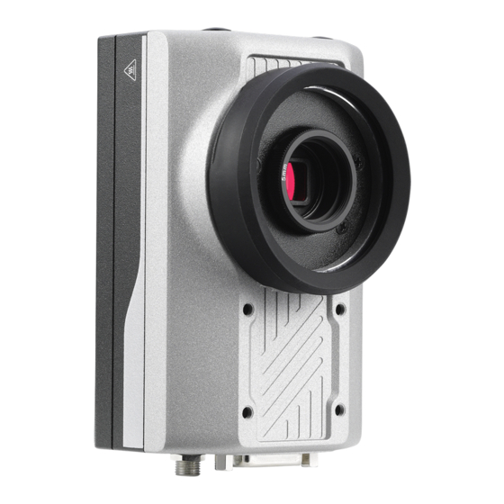
Leading EDGE COMPUTING 2.3 Front Side I/O and Connector Description Figure 2-5: Front Side I/O and Connectors Item Description C-mount type lens mount Image sensor Strobe/LED light mounting thread. See “LED Light Mounting Thread” on page 6. Table 2-5: Front Side I/O and Connectors Connectors and I/O... -
Page 23: Getting Started
NEON-1000-MDX Getting Started 3.1 Mounting the Device The NEON-1000-MDX can be mounted using the mounting screw holes on either the front (A) or back (B) sides. Le NEON-1000-MDX peut être monté à l'aide des trous de vis de montage sur les côtés avant (A) ou arrière (B). A: 4x M4 screws, L=6mm 4x vis M4, L=6mm B: 4x M4 screws, L=6mm... -
Page 24: Digital I/O Connections
Leading EDGE COMPUTING 3.2 Digital I/O Connections External devices such as trigger sensors, LED light controllers, or relays can be connected to the NEON-1000-MDX to implement different applications. This section shows how to connect such devices. Camera side control circuit photocoupler 470 ohm Max 5 V... -
Page 25: Attaching A Lens
NEON-1000-MDX 3.3 Attaching a Lens The NEON-1000-MDX is compatible with C-mount type lenses. Figure 3-4: Lens Attachment Assembly The transfer ring is preinstalled on the NEON-1000-MDX. The washer is used only with the NEON-102B-MDX. NOTE: NOTE: Getting Started... -
Page 26: Power And Peripheral Connections
Leading EDGE COMPUTING 3.4 Power and Peripheral Connections The NEON-1000-MDX can be powered from either a USB Type-C adapter or the DC jack. The USB Type-C connector also supports DisplayPort video signal and USB 3.0, which can be used to con- nect a keyboard and mouse. -
Page 27: Figure 3-6: Combined Power And Peripheral Connections
NEON-1000-MDX Keyboard & Mouse Power USB Type‐C HDMI Cord AC Power Monitor Adapter/Hub USB Type‐C Figure 3-6: Combined Power and Peripheral Connections This configuration requires an ADLINK USB Type-C adapter/hub (P/N 92-99090-1010). NOTE: NOTE: Getting Started... -
Page 28: Image Capture And Inference
Leading EDGE COMPUTING 3.5 Image Capture and Inference The NEON-1000-MDX does not come with software prein- stalled. To get the latest software and sample code for your product, contact ADLINK support at http://askanexpert.adlink- NOTE: NOTE: tech.com. ADLINK provides Python sample code files for testing the built-in Basler image capturing and inference features on the NEON- 1000-MDX. -
Page 29: Figure 3-7: Single-Shot Image Capture
NEON-1000-MDX The following steps illustrate how to execute the single-shot and continuous image capture sample code. 1. Go to the directory where the image capture sample code files are saved. 2. Find the image capture sample code file you want to execute (single-shot or continuous). -
Page 30: Image Capture And Inference Sample Code
Leading EDGE COMPUTING Figure 3-8: Continuous Image Capture Press ESC to terminate the application. NOTE: NOTE: 3.5.2 Image Capture and Inference Sample Code ADLINK provides an image capture and inference sample code ® built using the Intel Distribution of OpenVINO™ toolkit. The sam- ple code uses the pypylon API and inference YOLOv3 model to capture images and perform object detection, respectively. -
Page 31: Figure 3-9: Image Capture And Inference
NEON-1000-MDX The following steps illustrate how to execute the image capture and inference sample. 1. Go to the directory where the image capture and infer- ence sample code is saved. 2. Right-click to open the terminal (in the current directory). 3. -
Page 32: Using The Basler Pylon Utility
Leading EDGE COMPUTING 3.6 Using the Basler pylon Utility This section describes how to use the Basler pylon utility to cap- ture images and adjust, load, and save sensor settings. 3.6.1 Capturing Images with pylon The following steps illustrate how to capture images using the Basler pylon Viewer application. - Page 33 NEON-1000-MDX 3. Double-click the sensor name to open the image sensor tab. Basler daA1600-60uc is the image sensor for the NEON-102B- MDX. The sensor name that appears will reflect the model being used. NOTE: NOTE: 4. Click the Continuous Shot button to begin capturing images.
-
Page 34: Modifying Image Sensor Settings With Pylon
Leading EDGE COMPUTING After clicking the Continuous Shot button, the camera begins capturing images continuously and displays activity in the image sensor tab. 3.6.2 Modifying Image Sensor Settings with pylon The default NEON-1000-MDX image sensor settings may not be suitable for all applications. This section illustrates how to modify image sensor settings. - Page 35 NEON-1000-MDX 3.6.2.1 Loading Image Sensor Settings 1. Click the Files icon. 2. Go to /opt/pylon/bin and double-click pylonviewer or select the pylon Viewer in the launcher. Getting Started...
- Page 36 Leading EDGE COMPUTING 3. Double-click the sensor name to open the image sensor tab. Basler daA1600-60uc is the image sensor for the NEON-102B- MDX. The sensor name that appears will reflect the model being used. NOTE: NOTE: 4. Click Camera > Load Features... and select the appro- priate *.pfs file to load the desired image sensor settings.
- Page 37 NEON-1000-MDX After loading the file, the image sensor settings will be updated. You can view the settings under Features in the main window. Getting Started...
- Page 38 Leading EDGE COMPUTING 3.6.2.2 Modifying Image Sensor Settings 1. Click the Files button. 2. Go to /opt/pylon/bin and double-click pylonviewer, or select pylon Viewer in the launcher. Getting Started...
- Page 39 NEON-1000-MDX 3. Double-click the sensor name to open the image sensor tab. Basler daA1600-60uc is the image sensor for the NEON-102B- MDX. The sensor name that appears will reflect the model being used. NOTE: NOTE: Getting Started...
- Page 40 Leading EDGE COMPUTING 4. Modify the image sensor settings as needed. Getting Started...
- Page 41 NEON-1000-MDX 5. Click Camera > Save Features... from the main menu to save the modified settings to a file. Getting Started...
-
Page 42: Using Apis To Modify Image Sensor Settings
Leading EDGE COMPUTING 3.6.3 Using APIs to Modify Image Sensor Settings After opening the device, you can add the CFeaturePersis- tence::Load function to load features and modify the image sen- sor settings. You can find supporting documentation and additional sample code in the following directories: •... -
Page 43: Important Safety Instructions
NEON-1000-MDX Important Safety Instructions For user safety, please read and follow all instructions, Warnings, Cautions, and Notes marked in this manual and on the associated device before handling/operating the device, to avoid injury or damage. Read these safety instructions carefully ... - Page 44 Leading EDGE COMPUTING A Lithium-type battery may be provided for uninterrupted backup or emergency power. Risk of explosion if battery is replaced with one of an incorrect type; please dispose of used batteries appropriately. CAUTION: The device must be serviced by authorized technicians when: ...
-
Page 45: Consignes De Sécurité Importante
NEON-1000-MDX Consignes de Sécurité Importante S'il vous plaît prêter attention stricte à tous les avertissements et mises en garde figurant sur l'appareil, pour éviter des blessures ou des dommages. Lisez attentivement ces consignes de sécurité. Conservez le manuel de l'utilisateur pour pouvoir le consulter ultérieurement. - Page 46 Leading EDGE COMPUTING tenu que par du personnel technique qualifié à l'aide d'outils appropriés. Une batterie de type lithium peut être fournie pour une alimen- tation de secours ou une alimentation de secours ininterrom- pue. Risque d’explosion si la pile est remplacée par une autre de type incorrect.
-
Page 47: Getting Service
San Jose, CA 95138, USA Tel: +1-408-360-0200 Toll Free: +1-800-966-5200 (USA only) Fax: +1-408-360-0222 Email: info@adlinktech.com ADLINK Technology (China) Co., Ltd. 300 Fang Chun Rd., Zhangjiang Hi-Tech Park Pudong New Area, Shanghai, 201203 China Tel: +86-21-5132-8988 Fax: +86-21-5132-3588 Email: market@adlinktech.com...
Need help?
Do you have a question about the NEON-1000-MDX Series and is the answer not in the manual?
Questions and answers