Table of Contents
Advertisement
Quick Links
Advertisement
Table of Contents
Troubleshooting

Related Manuals for Teledyne Tekmar Atomx XYZ


Summary of Contents for Teledyne Tekmar Atomx XYZ
- Page 1 Atomx XYZ User Manual Part Number: 15-3200-074 Rev: B, June - 2018...
- Page 2 The companies indicated own the following trademarks: Tekmar .......... Teledyne Instruments, Inc. All other brands or product names are trademarks or registered trademarks of their respective owners. Contact Information Teledyne Tekmar 4736 Socialville Foster Road Mason, OH 45040 U.S.A www.teledynetekmar.com...
-
Page 3: Table Of Contents
1.4 Atomx XYZ Specifications ........ - Page 4 2.5 Atomx XYZ System Overview........2-6...
- Page 5 Chapter 4: Instrument Operations 4.1 Atomx XYZ Mode Descriptions ....... . . 4-1 4.2 Atomx XYZ Valve Output/Mechanism Chart .
- Page 6 5.24 Upgrade Autosampler Firmware....... 5-62 5.25 Upgrade Atomx XYZ TekLink Software ......5-65 5.26 Troubleshooting .
- Page 7 5.27 Returning the Atomx XYZ ........
- Page 8 2-3 Back of Atomx XYZ ......... . 2-7 2-4 Atomx XYZ Power Entry Module ....... . 2-8 2-5 GC I/O Cable Connection.
- Page 9 5-2 Right Side of Atomx XYZ ........
- Page 10 5-59 Alignment Complete ........5-53 5-60 Atomx XYZ Power Entry Module (PEM)......5-55 5-61 PEM Fuse Module Cover Open (PEM Assembly Removed for Clarity) .
- Page 11 A-2 Atomx XYZ Autosampler Electrical Schematic ..... A-2 A-3 Atomx XYZ Plumbing Diagram ....... . . A-3 A-4 Atomx XYZ - Basic Flow Diagram .
- Page 12 1-16 Atomx XYZ Components ........
-
Page 13: Warranty
You must adhere to and integrate the following instructions into your safety program when installing, using, and maintaining the Atomx XYZ. Failure to follow the proper instructions may invalidate the warranty. -
Page 14: Notations And Hazard Severity Levels
When replacement parts are required, ensure that qualified individuals use replacement parts specified by Teledyne Tekmar. Unauthorized parts and products can affect the product’s performance and jeopardize safety. Using look-alike substitutions may result in fire, electrical hazards, or improper operation. -
Page 15: Atomx Xyz Safety Symbols Defined
P.5 Atomx XYZ Safety Symbols Defined The Atomx XYZ instrument is labeled in compliance with the marking and nomenclature specified in the UL61010-1Ed. 3 (2012) safety standard. The following symbols and their associated signal words are used in the manual and on instrument labels. - Page 16 Risque de blessures aux yeux. Porter des lunettes de sécurité et autres équipements de protection personnel appropriés. Pinch Point Hazard! Keep hands and other appendages away. Danger d’écrasement! Garder les mains et autres membres éloignés. Lift Point! Point de Levage! Atomx XYZ Safety Symbols Defined P - 4 Atomx XYZ User Manual...
-
Page 17: Atomx Xyz Safety Labels
P.6 Atomx XYZ Safety Labels Electrical Ground Prise de terre WARNING: Electrical shock hazard. Do not operate without cover. DANGER: Risque d’électrocution. Ne pas utiliser sans capot. WARNING: To avoid electrical shock, disconnect supply before changing fuses. DANGER: Pour éviter le risque d’électrocution, débrancher l’alimentation avant de remplacer les fus- ibles. - Page 18 Do not plug the Atomx XYZ into an extension cord. An extension cord may overheat and cause a fire. Only replace the Atomx XYZ mains supply AC power cable with a UL listed cable of the same current and voltage rating.
- Page 19 To avoid injury to yourself or damage to the Atomx XYZ, do not exceed the recommended pressure settings. Observe safety regulations when handling pressurized gas. For more information see Matheson™ Gases Data Book (available from the Matheson Company, East Rutherford, New Jersey).
-
Page 20: Working Safely
GC and the 4-way tee, allow the components to cool to room temperature. 6-Port Valve Analytical Trap Sample Mount Sample Needle & Cup Sample Transfer Line Soil Valve 4-Way Tee Working Safely P - 8 Atomx XYZ User Manual... -
Page 21: Explanation Of Regulatory Marks
European Waste Electrical and Electronic Equipment Directive (WEEE, 2002/96/EC). Please contact Teledyne Tekmar or your local distributor for instructions on returning the system for proper disassembly and disposal. Contact Teledyne Tekmar Customer Support. - Page 22 P - 10 Atomx XYZ User Manual...
-
Page 23: Chapter 1: Introduction
The Atomx XYZ single needle design transfers liquid sample aliquots from the vial to the sparger. Low -level solid samples are purged directly in the vial, transferring to the trap. -
Page 24: Brief History
After a certain period of time at a constant temperature, the concentration of the volatile compounds in each phase will be stabilized, the chemical system will have reached equilibrium (Figure 1-1). Chapter 1: Introduction 1 - 2 Atomx XYZ User Manual... -
Page 25: Headspace Equilibrium Diagram
These limitations are determined by the compounds of interest in the sample and the sorbent material used in the trap. Chapter 1: Introduction 1 - 3 Atomx XYZ User Manual... -
Page 26: Trapping, Adsorption And Desorption
The desorption is carried out by back-flushing the trap, ensuring that the less volatile, or heavier, analytes never come in contact with the stronger sorbent. Chapter 1: Introduction 1 - 4 Atomx XYZ User Manual... -
Page 27: Atomx Xyz Specifications
1-10. GC Interface Designed to interface with virtually all commercially available GC instruments. Column Compatibility Teledyne Tekmar recommends the use of 20 m x 0.18 mm ID Fast Volatiles columns. Chapter 1: Introduction 1 - 5 Atomx XYZ User Manual... -
Page 28: Performance Specifications
Environmental, Food and Beverage, Petrochemical, & Plastics & Polymers Certifications Certifications are listed on the Declaration of Conformity (DOC). The DOC is included with the instrument, in the shipping box. Chapter 1: Introduction 1 - 6 Atomx XYZ User Manual... -
Page 29: Sample Needle
Programmable automatic dilutions of methanolic extract of 1:100 or 1:50, 5 mL sample volumes. a. Includes all types of soils and sediments. Sample procedure: Automated methanol extraction and subsequent dilution per USEPA 5035 high-level soil methodology. Chapter 1: Introduction 1 - 7 Atomx XYZ User Manual... -
Page 30: Internal Standard Injection
(US Patent 7,651,866). Electronic Pressure Monitor Automatic leak check and over-pressure sensing capability. Ability to record purge and bake pressures for each sample. Chapter 1: Introduction 1 - 8 Atomx XYZ User Manual... -
Page 31: Electrical Requirements
220-240 VAC +/- 10%, 50/60Hz, 5.0A, 1150W External Circuits The circuit used to power the Atomx XYZ should be protected by a Certi- fied/Listed 15/20 Circuit Breaker for short circuit protection. The AC Power Cable supplied with the Atomx XYZ is compliant with applicable safety standards. - Page 32 4 °C (39.2 °F) until they are sampled. Guardian Foam Sensor and Eliminator Optional Guardian Foam Sensor and Foam Eliminator senses foam, stops (Optional) purge, and adds defoaming agent for samples prone to foaming. Chapter 1: Introduction 1 - 10 Atomx XYZ User Manual...
-
Page 33: Atomx Xyz Component Overview
The analytical trap heating jacket heats the analytical trap to a consistent tempera- Resistance Temperature Detector ture defined in the Atomx XYZ TekLink software. The Resistance Temperature Detec- (RTD) tor (RTD) in the heating jacket verifies this temperature to the software. - Page 34 Communicates to the GC via GC I/O cable and the controlling PC via the USB Port. Board) DC Valve Control Board Actuates the Atomx XYZ solenoid valves, as well as the analytical trap and the Mois- ture Control System (MCS) cooling fans. Internal Standard Valve Control Controls all Internal Standard valve outputs.
-
Page 35: Sample Mount And Sparger
The front panel contains a heated sample mount and glass sparge vessel. The sample mount is heated via the 6-port valve oven plate on one end and a cartridge heater inside the mount itself. A standard 5 mL frit sparger is included with the Atomx XYZ. The following options are also available: ... -
Page 36: Internal Standard Pressure Regulator
(i.e. Presweep A&B). 1.5.4 Internal Standard Vessels Atomx XYZ is equipped with three 15 mL amber internal standard vessels. The amber color prevents transmission of UV radiation, preserving standard integrity. Vessels are sealed with a PEEK cap to prevent adsorption and contamination of the standard solution. -
Page 37: Syringe Drive With Sweepable 25 Ml Syringe
"6-Port Syringe Valve". Figure 1-5 Syringe 1.5.6 Sample Needle The Atomx XYZ uses a patented 3-stage sample needle to displace sample from the vial (versus aspirating per USEPA methodologies), purge in the vial and complete methanol extractions. Figure 1-6... -
Page 38: Xyz Autosampler Pick And Place Assembly
If the gripper is not functioning correctly, first ensure the sample gas supply is on, properly connected, and supplying 65 - 100 psi (4.48 bar - 6.89 bar) to the Atomx XYZ. 1.5.8 Elevator The elevator moves from the down position where the vial is loaded, to the up position where the vial is pierced by the 3-stage needle for sampling. -
Page 39: Vial Mixer Assembly
1.5.10 Status Light The Atomx XYZ logo changes color to indicate the instrument’s state. The status related to each color is shown in Table 1-17 "Status Light Indications". The Atomx XYZ logo is lit using an LED board behind the panel. -
Page 40: Sample Purge Gas Inlet
TekLink. 1.5.12 Mass Flow Controller (MFC) The Atomx XYZ incorporates a patented mass flow controller to monitor and control the gas flow rates throughout the entire purge and trap process. Once set, the parameters remain precisely controlled throughout all modes of operation and achieve highly repeatable analyses. -
Page 41: Analytical Trap
Resistance Temperature Detector (RTD) inside the trap heating jacket. The trap compartment door is equipped with a magnetic switch and must be closed for the system to operate. Figure 1-11 Atomx XYZ Analytical Trap Compartment Resistance Temperature Detector (RTD) Cooling Fan... -
Page 42: Carrier Gas Inlet Line/Heated Sample Transfer Line
VOCs being transferred to the GC column stay in their gaseous state. Carrier gas makes a passive loop through the Atomx XYZ and returns, unchanged, to the GC through the transfer line. GC carrier gas is independently controlled through the GC or an External Pressure Control (EPC). -
Page 43: Valving
1.5.17 Valving The Atomx XYZ contains the valves shown in Table 1-18 "Valve Overview". The internal standard pressure regulator is also located on the valve manifold. Table 1-18 Valve Overview Solenoid Valves 9 (standard configuration) or 11 (optional Guardian Foam Eliminator configuration) 24 VDC... -
Page 44: Heated 6-Port Valve
Heated Soil Valve The soil valve is an On/Off heated 24VDC solenoid used for solid (soil) samples purged in the vial (with or without methanol extraction). Figure 1-16 Soil Valve Chapter 1: Introduction 1 - 22 Atomx XYZ User Manual... -
Page 45: Optional Accessories
Resistance Temperature Detector (RTD) that is slid over the sample glassware. The heater is capable of heating the sparger from 35 °C to 100 °C (95 °F to 212 °F). Figure 1-18 Sparge Vessel Heater Chapter 1: Introduction 1 - 23 Atomx XYZ User Manual... -
Page 46: Vial Chiller Plate
Atomx XYZ from the adverse effects of liquid entering the gas pathway. The Atomx XYZ can be equipped with only the foam sensor to trigger an alert or the sensor and eliminator to trigger an alert, remove the foam from the sample, and rerun. -
Page 47: Chapter 2: Installation And Setup
2.1.2 Operating Environment The Atomx XYZ operates at temperatures between 10 °C and 30 °C (50 °F and 86 °F) with humidity levels between 10% and 90%. These temperatures and humidity levels are consistent with a standard lab environment and should pose no difficulty. -
Page 48: Work Surface Requirements
2.1.3 Work Surface Requirements The Atomx XYZ is 49.5 cm (19.5”) high, 70.1 cm (27.6”) wide, 58.4 cm (23”) deep, and weighs 43.09 kg (95 lbs). Caution The Atomx XYZ weighs 43.2 kg (95 lbs). If this weight exceeds your lifting ability, lift and position the Atomx XYZ with two people. -
Page 49: Gas Supply Requirements
3. The diameter of the tubing that supplies the gas depends on the maximum pressure drop allowable for the configuration. If the helium supply is close to the Atomx XYZ, use the pre-installed blue 1/8” (0.32 cm) tubing. ... -
Page 50: Minimum Computer Requirements
PTFE tape. Volatile materials in the dope and/or low-grade tape will contaminate the tubing. 2.1.6 Minimum Computer Requirements Connect the Atomx XYZ to a computer that meets or exceeds the specifications shown in Table 2-1 "Minimum Computer Requirements": Table 2-1 Minimum Computer Requirements... -
Page 51: Unpacking The Atomx Xyz
2.3 Unpacking the Atomx XYZ Caution The Atomx XYZ weighs 95 lbs (43.1 kg). If this weight exceeds your lifting ability, lift and position the Atomx XYZ with two people. When lifting the Atomx XYZ, use the designated lift points. -
Page 52: Atomx Xyz System Overview
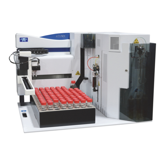
2.5 Atomx XYZ System Overview Figure 2-2 Front of Atomx XYZ Sample Vial Cup Sample Analytical Trap Sample Mount Status Light and Elevator Needle Compartment Sparger XYZ Robotic Syringe Internal Sample Vessels Chapter 2: Installation and Setup 2 - 6... -
Page 53: Back Of Atomx Xyz
Figure 2-3 Back of Atomx XYZ GC I/O Connection USB Connection Heated Sample Transfer Line and Carrier Gas Line Power Entry Module Blue Sample Gas Tubing Drain Tubing Methanol Tubing Clear DI Water Tubing Chapter 2: Installation and Setup 2 - 7... -
Page 54: Electrical And Data Connections
2. Plug the AC power cord into the PEM and connect it to a properly rated and grounded AC receptacle. WARNING The circuit used to power the Atomx XYZ should be protected by a Certified/Listed 15/20 Circuit Breaker for short circuit protection. WARNING Ensure the power cable is routed away from, and is not capable of contacting, any hot surface. -
Page 55: Gc I/O (Input/Output) Connection
1. Connect the GC I/O cable to the gas chromatograph according to the GC instructions. 2. Connect the GC I/O cable to the GC I/O port on the back of the Atomx XYZ. 3. Once connected, communication to the GC will be configured via the >C... -
Page 56: Gas Connections
(found in the Installation Kit Box) to the laboratory helium or nitrogen supply line. 2. Route the blue 1/8” (0.32 cm) sample purge gas tubing from the Atomx XYZ to the tee and connect. Insert the tubing into the union, and then tighten with a 7/16”... -
Page 57: Atomx Xyz Carrier Gas Supply And Heated Sample Transfer Line Connection To The Gas Chromatograph (Gc)
Transfer Line Connection to the Gas Chromatograph (GC) The Atomx XYZ connects to the regulated carrier gas of the GC at a location after the GC Electronic Pressure Control (EPC) and prior to the GC injection port. By connecting at this location, the GC regulated carrier gas is routed through the Atomx XYZ to carry desorbed VOCs from the analytical trap back to the GC sample inlet. - Page 58 5/16” wrench to hold the center of the union and another to tighten the nut. 4. Connect the Atomx XYZ carrier gas line (outside tubing) to the union on the tubing from the GC Electronic Pressure Control (EPC). Connect the union to the tubing in the same manner as previous procedures.
-
Page 59: Liquid Connections
The Atomx XYZ requires a source of DI water for system rinsing, auto-blanks and dilutions. The Atomx XYZ is supplied with a 10 L reservoir for the DI water supply. To avoid contamination problems, use blank (organic-free) water. Follow the instructions below to supply the instrument with DI water: 1. -
Page 60: Optional Methanol Reservoir Connection
NOTE Do not locate the water reservoir more than 4 ft (1.22 m) below the Atomx XYZ unit. Height differentials larger than 4 ft (1.22 m) can cause damage to the syringe due to siphoning. Figure 2-10 DI Water Tubing (Weights Not Shown) 2.8.3 Optional Methanol Reservoir Connection... -
Page 61: Optional Vial Chiller Plate Tubing Connections
Figure 2-11 Methanol Supply Tubing 2.8.4 Optional Vial Chiller Plate Tubing Connections If the instrument configuration includes vial chilling, connect the Atomx XYZ chiller plate to a recirculating bath. Inlet and outlet hose connections require 1/4” (0.64 cm) ID rubber tubing. -
Page 62: Install Atomx Xyz Teklink Software
For computer requirements refer to Section 2.1.6 "Minimum Computer Requirements". 1. Ensure the controlling computer is not connected to the Atomx XYZ via USB cable. 2. Power on the controlling computer. 3. Insert the Atomx XYZ TekLink Software Installation CD into the computer’s disc drive. -
Page 63: Release Notes
8. The wizard will request where to install the software. Use the default software installation location shown or browse to a custom location. Once chosen, select the N to continue. UTTON Chapter 2: Installation and Setup 2 - 17 Atomx XYZ User Manual... - Page 64 TART OLDER shortcut. Use the default location or browse to a custom location for the software shortcut. Once chosen, select the N to continue. UTTON Chapter 2: Installation and Setup 2 - 18 Atomx XYZ User Manual...
- Page 65 Select if you would like the software icon to be installed on the desktop by placing a check mark beside the selection. Once chosen, select the N to continue. UTTON Figure 2-20 Select Additional Tasks Chapter 2: Installation and Setup 2 - 19 Atomx XYZ User Manual...
- Page 66 12. The software is now ready to install. Select the I to install the NSTALL UTTON software. Figure 2-21 Ready to Install 13. The software installation progress will be shown. Figure 2-22 Installation in Progress Chapter 2: Installation and Setup 2 - 20 Atomx XYZ User Manual...
- Page 67 15. Once the software is installed, the C will be shown. Select the OMPLETION CREEN to complete the installation and close the wizard. INISH UTTON Figure 2-24 Software Completion Chapter 2: Installation and Setup 2 - 21 Atomx XYZ User Manual...
-
Page 68: Connect The Usb Interface Cable
2.9.1 Connect the USB Interface Cable 1. Connect the supplied USB cable to the USB port at the back of the Atomx XYZ, then to a USB port on the computer. 2. Power on the Atomx XYZ. Figure 2-25 Atomx XYZ USB Connection 2.10 Create an Instrument Profile... -
Page 69: Options Tab
NOTE If other Atomx XYZ instruments are on the same network, use the name and description to differentiate one instrument from another. This will assist when defining system properties and settings. Enter a D that easily identifies the instrument. ... -
Page 70: Leak Check Tab
4. On the L HECK Customize L pressure settings, HECK RESSURIZE HECK and L (amount of change in pressurization that indicates a HECK ELTA leak). Figure 2-28 Leak Check Tab Chapter 2: Installation and Setup 2 - 24 Atomx XYZ User Manual... -
Page 71: Guardian Foam Sensor And Foam Eliminator (Optional)
XYZ’s gas pathway. When combined with the optional foam eliminator, a defoamer is added to the sample. If ordered with the Atomx XYZ, the Guardian Foam Sensor and/or Foam Eliminator will be installed. To retrofit a Atomx XYZ with the Guardian Foam Sensor and/or Foam Eliminator refer to the installation instruction sheet included with the Guardian Foam Sensor and Foam Eliminator. -
Page 72: Atomx Xyz With Guardian Foam Sensor
2.11.2 Atomx XYZ with Guardian Foam Sensor and Foam Eliminator 1. When foam is sensed, the Atomx XYZ shuts off the purge gas. The purge clock is stopped and the Foam Transfer Valve is activated to add a defoaming agent. -
Page 73: Preparing Di Water
Figure 2-30 Configuration Dialog- Guardian Foam Sensor 2.12 Preparing DI Water The Atomx XYZ requires a source of DI water for system rinsing, auto-blanks, dilutions and high temperature system rinse. To avoid contamination problems, use blank (organic-free) water. Teledyne Tekmar recommends using deionized (DI) water. Several methods for preparing blank water are listed below: ... -
Page 74: Preparing Working Standards
E = Stock standard concentration (ppm) Example A = 5 ppb B = 25 mL C = 2 µL D = 10 mL E - 2000 ppm Chapter 2: Installation and Setup 2 - 28 Atomx XYZ User Manual... -
Page 75: Chapter 3: Atomx Xyz Teklink Software Overview
"Minimum Computer Requirements". For information on installing Atomx XYZ TekLink refer to Section 2.9 "Install Atomx XYZ TekLink Software". 3.1 About Atomx XYZ TekLink Software Atomx XYZ TekLink is a software user interface designed for the following functions: Define custom methods or operating sequences that meet analytical requirements by defining Standby, Purge, Desorb and Bake parameters. -
Page 76: Pinnable" Screens
(according to screen). Figure 3-3 Schedules Screen Title Bar Instrument Profile Schedule Name Method Type Instrument Profile Method Type Method Name Chapter 3: Atomx XYZ TekLink Software Overview 3 - 2 Atomx XYZ User Manual... -
Page 77: Open, Save, Load, And Print Buttons
- Save the currently open method or schedule. UTTON NOTE Atomx XYZ TekLink includes default water, soil, and methanol extraction methods that cannot be over-written. To use a default method, open it from the Method Screen or select it from the Method Drop-down on the Schedules Screen. -
Page 78: Delete At Next Archive Check-Box
CHEDULE IALOG OURCE DOWN NOTE Archive settings and the Archive Now command are located under Tools>System Properties>Data Tab. Figure 3-7 Open Schedule Dialog Source Drop-down Menu Chapter 3: Atomx XYZ TekLink Software Overview 3 - 4 Atomx XYZ User Manual... -
Page 79: Primary Screens
OOLS CREEN configuration options and settings, and sample, instrument, and error logs. - Atomx XYZ TekLink Help is context sensitive and provides information on the software and instrument functionality. Figure 3-8 Home Screen Chapter 3: Atomx XYZ TekLink Software Overview... -
Page 80: Instrument Status Panel
Current/Set-Point Temperature by Zone NOTE Right-clicking on the Zones Panel of the Instrument Status Screen will show additional display options. Figure 3-10 Instrument Status Zone Display Options Chapter 3: Atomx XYZ TekLink Software Overview 3 - 6 Atomx XYZ User Manual... -
Page 81: Methods Screen
TANDBY URGE ESORB method parameters. Because method parameters vary according to the type of analysis conducted on the Atomx XYZ, the user is first prompted to select a method type (W ATER ETHANOL Figure 3-11 Choose Method Type Dialog Once the method type is selected, the header of the screen and the parameters contained on each of the screen’s tabs will correspond to that type of analysis. -
Page 82: Purge Tab
Parameters vary according to the method type chosen. Water Method Purge Tab Options NOTE Teledyne Tekmar recommends a sample gas flow of 40 mL/min ±5 mL for 11 minutes to achieve a 440 mL purge volume. Chapter 3: Atomx XYZ TekLink Software Overview... - Page 83 Purge to ensure that all samples are purged under the desired conditions. Figure 3-14 Waters Methods Screen - Purge Tab - Sparge Vessel Heater Enabled Sparge Vessel Heater Enabled Chapter 3: Atomx XYZ TekLink Software Overview 3 - 9 Atomx XYZ User Manual...
-
Page 84: Soil Methods Screen - Purge Tab
This parameter allows for the addition of water to soil samples. It will be necessary to add water if the user wishes to add internal standards to the sample via the automated standard addition feature of the Atomx XYZ. Figure 3-15 Soil Methods Screen - Purge Tab... -
Page 85: Methanol Extraction Methods Screen - Purge Tab
Ensure that adequate settling time is allowed to prevent particulate matter from being drawn into the needle and syringe. Figure 3-16 Methanol Extraction Methods Screen - Purge Tab Chapter 3: Atomx XYZ TekLink Software Overview 3 - 11 Atomx XYZ User Manual... -
Page 86: Desorb Tab
B beginning and end (the latter two are typically ESORB ESORB used in conjunction with a cryofocusing inlet). Figure 3-17 Waters Methods Screen - Desorb Tab Chapter 3: Atomx XYZ TekLink Software Overview 3 - 12 Atomx XYZ User Manual... -
Page 87: Bake Tab
Volume of methanol to be used to rinse the sparger. A volume of one or two milliliters larger than the sample volume should be employed to ensure adequate rinsing of the glassware. Figure 3-18 Water Methods Screen - Bake Tab Chapter 3: Atomx XYZ TekLink Software Overview 3 - 13 Atomx XYZ User Manual... -
Page 88: Schedules Screen
- A drop-down menu that allows the selection of default water, soil ETHOD and methanol methods, as well as any custom methods saved in the Current or Archived Data folders. Chapter 3: Atomx XYZ TekLink Software Overview 3 - 14 Atomx XYZ User Manual... - Page 89 STD1, STD2 and STD3 - These columns permit the addition of check and/or internal standards to the sample when running water and soil methods. When the Atomx XYZ is running a methanol extraction sample, STD3 is reserved for a matrix spike to be added to the vial prior to extraction. NOTE...
-
Page 90: Tools Screen
OOLS CREEN diagnostics. It also contains software preferences and configuration options and settings as well as sample, instrument, and error logs. Figure 3-21 Tools Screen Chapter 3: Atomx XYZ TekLink Software Overview 3 - 16 Atomx XYZ User Manual... -
Page 91: Prime Menu
3.6.2 Commands Menu Leak Check Activates the Atomx XYZ leak check function. The system performs a leak check by closing specific valves and shutting down the Mass Flow Controller (MFC) to isolate the pressurized system. Once isolated, the Atomx XYZ will take pressure readings to identify any pressure loss that would indicate a leak. - Page 92 Moisture Control System Bake Temperature Bake Flow DI Water and Methanol Bake Rinse The dialog contains selection boxes for the following sample pathway rinses to reduce carryover: Chapter 3: Atomx XYZ TekLink Software Overview 3 - 18 Atomx XYZ User Manual...
- Page 93 The wizard is used to align the X, Y, and Z axis of the autosampler arms through a sequence of steps. Refer to the Section 5.18 "XYZ Autosampler Alignment". Chapter 3: Atomx XYZ TekLink Software Overview 3 - 19 Atomx XYZ User Manual...
-
Page 94: System Menu
Tools>Instrument Manager unless the “Show deactivated instrument profiles” Check-Box is selected in that dialog. Figure 3-24 Tools - Configuration - General Tab Chapter 3: Atomx XYZ TekLink Software Overview 3 - 20 Atomx XYZ User Manual... - Page 95 GC. If the model is not found from the drop-down list, refer to the GC manufacturer’s instructions and use the S :63 or U TANDARD ADIO UTTONS Figure 3-25 Tools - Configuration - Options Tab Chapter 3: Atomx XYZ TekLink Software Overview 3 - 21 Atomx XYZ User Manual...
-
Page 96: Leak Check Dialog
ELTA indicates a leak. Figure 3-26 Tools - Configuration - Leak Check Tab NOTE For the Leak Check procedure refer to Section 5.9 "System Leak Check". Chapter 3: Atomx XYZ TekLink Software Overview 3 - 22 Atomx XYZ User Manual... -
Page 97: System Properties Dialog
YSTEM ROPERTIES IALO configuration and histories (sample, instrument, and error). The M contains a selection box to display an on-screen keyboard. Figure 3-28 System Properties Dialog Chapter 3: Atomx XYZ TekLink Software Overview 3 - 23 Atomx XYZ User Manual... -
Page 98: System Properties - Data Tab
USING THE MOST RECENT SETTINGS information. NOTE Data cannot be archived when a schedule is running. Archives are full backups of all current data used by Atomx XYZ TekLink. If the is selected on the M or S ELETE AFTER THE NEXT ARCHIVE... - Page 99 RROR ISTORY to refine results. When troubleshooting, information from the V VENT ILER ISTORY may be requested by a Teledyne Tekmar Customer Support Representative. Use the or E RINT XPORT UTTONS Figure 3-31 History Log - Sample History Chapter 3: Atomx XYZ TekLink Software Overview...
- Page 100 Event filters can be returned to their default settings by selecting “Click here to return to the default filter for this view”. Figure 3-33 History Log Event Filter Chapter 3: Atomx XYZ TekLink Software Overview 3 - 26 Atomx XYZ User Manual...
-
Page 101: About Dialog
Atomx XYZ TekLink software and the BOUT IALOG firmware installed on the Atomx XYZ. When troubleshooting, information from the may be requested by a Teledyne Tekmar Customer Support B O U T I A L O G Representative. -
Page 102: Diagnostics
3.6.4 Diagnostics Valves and Flows The V provides discrete control of the Atomx XYZ valves, fans, ALVES AND LOWS CREEN and Mass Flow Controller (MFC) for diagnostics and troubleshooting. The MFC flow rate can be manually set and the actual flow and pressure can be observed. The beeper and banner board (Instrument Status Light) can also be tested on this screen. -
Page 103: Arm/Elevator
- Used to manually open and close the gripper. This RIPPER LOSE control is frequently used to insert the alignment probe into the gripper for the autosampler alignment procedure. Chapter 3: Atomx XYZ TekLink Software Overview 3 - 29 Atomx XYZ User Manual... -
Page 104: Pumper Diagnostics
Printed Circuit Boards (PCB). The current firmware version can be viewed via >A (Figure 3-34). OOLS BOUT UTTON NOTE For information on upgrading the XYZ autosampler firmware, refer to Section 5.24 "Upgrade Autosampler Firmware". Chapter 3: Atomx XYZ TekLink Software Overview 3 - 30 Atomx XYZ User Manual... -
Page 105: Benchmark Test
To access benchmark test results select T >V OOLS ISTORY >I NSTRUMENT ISTORY NOTE For information on using the benchmark test function refer to Section 5.26.1 "Benchmark Test". Figure 3-39 Benchmark Test Chapter 3: Atomx XYZ TekLink Software Overview 3 - 31 Atomx XYZ User Manual... -
Page 106: Add, Connect And Deactivate An Instrument Profile
On the G ENERAL Enter a name for the instrument profile. If there are other Atomx XYZ instruments on the network, use the name and description to differentiate one from another. Enter a description that easily identifies the instrument. -
Page 107: Options Tab
. If the specific model of the GC is not shown in the drop-down menu, use the S :63 or U :31 check-box according to the GC TANDARD manufacturer’s User Manual instructions. Figure 3-41 Options Tab Chapter 3: Atomx XYZ TekLink Software Overview 3 - 33 Atomx XYZ User Manual... -
Page 108: Deactivate An Instrument Profile
1. From the H select the T CREEN OOLS UTTON 2. On the T select the C to display the OOLS CREEN ONFIGURATION UTTON ONFIGURATION IALOG Chapter 3: Atomx XYZ TekLink Software Overview 3 - 34 Atomx XYZ User Manual... -
Page 109: Using The Methods Screen
3.8.2 Default Methods To use the default water, soil or methanol method provided with Atomx XYZ TekLink, open it from the M or select it from the S... -
Page 110: Open A Method
Figure 3-44 Choose Method Type Chapter 3: Atomx XYZ TekLink Software Overview 3 - 36 Atomx XYZ User Manual... - Page 111 ALUE OLUMN NOTE For information on parameters of note refer to Section 3.4 "Methods Screen". Also refer to Section 4.4 "Method Parameters". Chapter 3: Atomx XYZ TekLink Software Overview 3 - 37 Atomx XYZ User Manual...
- Page 112 Note that the title bar on the Methods Screen updates with the method name. Figure 3-47 Save Method As Dialog Name Method Figure 3-48 New Method Saved - Name in Title Bar New Method Name Chapter 3: Atomx XYZ TekLink Software Overview 3 - 38 Atomx XYZ User Manual...
-
Page 113: Load The Method
3.8.5 Load the Method Select the L to prompt the Atomx XYZ to begin using method ETHOD UTTON parameters immediately. After temperature set-points are reached, the system will go into standby/purge ready. If the method is not loaded from the M... -
Page 114: Schedules Screen Right-Click Options
<Enter>. The zero will turn to BLK indicating a blank in the schedule line selected (Line 1 in Figure 3-51). Alternatively right-click in the V OLUMN and select U SE BLANK INSTEAD OF VIAL Chapter 3: Atomx XYZ TekLink Software Overview 3 - 40 Atomx XYZ User Manual... -
Page 115: Select Method Dialog
OLUMN on the I via T >C NSTRUMENT ONFIGURATION CREEN OOLS ONFIGURATION . Enter a sample ID in the field. UTTON Figure 3-53 Sample ID Column Chapter 3: Atomx XYZ TekLink Software Overview 3 - 41 Atomx XYZ User Manual... -
Page 116: Save Schedule
UTTON CHEDULE IALOG name for the schedule can be entered. Select the O to save the schedule. UTTON Figure 3-55 Save Schedule Name Schedule Chapter 3: Atomx XYZ TekLink Software Overview 3 - 42 Atomx XYZ User Manual... -
Page 117: Print Schedule
M was not previously loaded from the ETHOD DOWN IELD , it will be loaded when the schedule is loaded and the Atomx XYZ will ETHODS CREEN begin using those method parameters. Once the schedule is loaded, the schedule’s S... -
Page 118: Step Schedule
H will change to an A . Select the A UTTON UTTON UTTON resume the schedule. Figure 3-58 Schedule Hold - Instrument Status Panel Chapter 3: Atomx XYZ TekLink Software Overview 3 - 44 Atomx XYZ User Manual... -
Page 119: Abort A Sample Or Schedule
3. The E NTIRE CHEDULE AFTER URRENT AMPLE Figure 3-59 Abort Dialog 3. Once the type of abort has been selected, Atomx XYZ TekLink will prompt to confirm the abort command using the C on the S ONFIRM UTTON CHEDULES... -
Page 120: Data Storage Location And Archiving Data
3.10 Data Storage Location and Archiving Data Archives are full backups of all data used by Atomx XYZ TekLink including method, s c h e d u l e , c o n f i g u r a t i o n , h i s t o r y a n d a r c h i v e s . T h e d a t a i s s t o r e d i n C:\ProgramData\Teledyne Tekmar\VOC AtomxXYZ TekLink Data by default, and cannot be changed. -
Page 121: Chapter 4: Instrument Operations
Preheat Purge When the Atomx XYZ is working in conjunction with the sparge vessel heater, this mode allows the sample to reach a uniform programmed temperature, prior to sample purging. Purge This is a VOC extraction mode in which the inert gas (such as helium) is dispersed through the sample matrix in the sparger (or in the sample vial if a soil) for a preset time and flow. - Page 122 This mode allows methanol to be introduced into the sparger for syringe, glassware and line rinsing, to clean the system between samples. Methanol Rinse Drain This mode drains the methanol, introduced to the sample glassware during the Methanol Rinse Mode, from the system. Chapter 4: Instrument Operations 4 - 2 Atomx XYZ User Manual...
-
Page 123: Atomx Xyz Valve Output/Mechanism Chart
4.2 Atomx XYZ Valve Output/Mechanism Chart 4.2.1 Waters Chapter 4: Instrument Operations 4 - 3 Atomx XYZ User Manual... - Page 124 Waters (Continued) Chapter 4: Instrument Operations 4 - 4 Atomx XYZ User Manual...
-
Page 125: Soils
4.2.2 Soils Chapter 4: Instrument Operations 4 - 5 Atomx XYZ User Manual... -
Page 126: Methanol Extraction
4.2.3 Methanol Extraction Chapter 4: Instrument Operations 4 - 6 Atomx XYZ User Manual... - Page 127 Methanol Extraction (Continued) Chapter 4: Instrument Operations 4 - 7 Atomx XYZ User Manual...
-
Page 128: Optimization/Method Development
The temperature range for the Atomx XYZ sample mount is 35 °C to 100 °C (95 °F to 212 °F). The typical sample mount temperature is 90 °C. In some cases the sample mount will be set to ambient temperature to allow for condensation of water prior to entering the sample pathway. - Page 129 Contact a Teledyne Tekmar Customer Support Representative using the information in Section P.2 "Teledyne Tekmar Customer Support Center" prior to attempting the high temperature cleaning process. Chapter 4: Instrument Operations...
-
Page 130: Purge Mode
Desorb Ready Mode indicates that the trap has been loaded with VOCs and the Atomx XYZ is ready to desorb. If the GC is not ready, the Atomx XYZ will wait for the GC during this mode. While the Atomx XYZ is in this mode, there is no flow or heat through the trap;... -
Page 131: Desorb Mode
A typical desorb preheat temperature is 5 °C (41 °F) below the desorb temperature. The Atomx XYZ will hold in this mode for 0.33 min to ensure full heat transfer to the center of the trap. 4.3.5 Desorb Mode In desorb, the 6-port valve rotates to backflush analytes from the analytical trap to the GC. -
Page 132: Method Parameters
4.4 Method Parameters 4.4.1 Water Chapter 4: Instrument Operations 4 - 12 Atomx XYZ User Manual... -
Page 133: Soil
4.4.2 Soil Chapter 4: Instrument Operations 4 - 13 Atomx XYZ User Manual... -
Page 134: Methanol Extraction
4.4.3 Methanol Extraction Chapter 4: Instrument Operations 4 - 14 Atomx XYZ User Manual... -
Page 135: Analytical Trap Recommended Operating Conditions
(#10) Tenax®/Silica Gel/Carbosieve® 14-9909-403 S-III (#11) VPH Trap (Proprietary) 15-0884-403 (K) Vocarb® 3000 14-5864-403 Vocarb® 4000 14-5865-403 BTEX™ 14-5866-403 BTEX™ + MTBE 14-9333-403 a. Uses a different mesh size. Chapter 4: Instrument Operations 4 - 15 Atomx XYZ User Manual... - Page 136 Chapter 4: Instrument Operations 4 - 16 Atomx XYZ User Manual...
-
Page 137: Chapter 5: Maintenance And Troubleshooting
Chapter 5: Maintenance and Troubleshooting 5.1 Maintenance Safety NOTE Caution and Warning Symbols are defined in Section P.5 "Atomx XYZ Safety Symbols Defined" and Section P.6 "Atomx XYZ Safety Labels". Les symboles d’Alerte et de Danger sont définis dans la section P.5 “Symboles Sécurité... -
Page 138: Preventative Maintenance Checks
5.3 Preventative Maintenance Checks A carefully designed and faithfully executed Preventative Maintenance Program is the best method for maintaining the Atomx XYZ. Adherence to scheduled maintenance in the areas of cleaning, checking of parts, and lubrication will help continue the performance standards of the unit and decrease the possibility of down time. -
Page 139: Monthly Maintenance Checks
Clean the autosampler according to the quarterly cleaning proce- dure. Refer to Section 5.17.2 "Quarterly Autosampler Cleaning". NOTE The Installation Kit Box includes most of the items needed for routine maintenance of the Atomx XYZ. Chapter 5: Maintenance and Troubleshooting 5 - 3 Atomx XYZ User Manual... -
Page 140: Preventative Maintenance Chart
Daily & Weekly Maintenance Items Inspect Sparger Glassware Inspect Drain Tubing Initials & Date Quarterly Daily, Weekly and Monthly Maintenance Items Lubricate the Atomx XYZ Elevator Initials & Date Chapter 5: Maintenance and Troubleshooting 5 - 4 Atomx XYZ User Manual... -
Page 141: Gc In/Out (I/O) Cable And Gc Type Reference
NOTE If Table 5-6 "GC I/O Cable and GC System Reference" does not contain your GC System, contact Teledyne Tekmar Customer Support using the contact information in Section 5.29 "Technical Assistance". Table 5-6 GC I/O Cable and GC System Reference... -
Page 142: Instrument Access Panels
Remove the Phillips screws from the side panel that is being removed. WARNING The Atomx XYZ is designed to keep liquid spills from coming in contact with electronics inside the unit. The Atomx XYZ access panels must be installed prior to turning the instrument ON. -
Page 143: Right Side Of Atomx Xyz
Figure 5-2 Right Side of Atomx XYZ Right Access Panel Figure 5-3 Analytical Trap Compartment and Sparger Panel Open Moisture Control System (MCS) Resistance Temperature Detector (RTD) Heated Sample Mount Analytical Trap in Trap Heater Jacket Analytical Trap Compartment Sparger... -
Page 144: Plumbing Overview
5.7 Plumbing Overview NOTE Also refer to Section A.3 "Atomx XYZ Plumbing Diagram". Figure 5-4 Plumbing Components 4-Way Tee 6-Port Valve Valve Manifold Sample Mount and Sparger Analytical Trap Moisture Control System Soil Valve Water Heater/Reservoir IS Pressure Regulator Syringe... - Page 145 Figure 5-5 Plumbing Components 6-Port Valve, MCS, and 4-Way Tee Carrier Gas Inlet Line/Heated Sample Transfer Line Valve Manifold Hot Water Heater/Reservoir Chapter 5: Maintenance and Troubleshooting 5 - 9 Atomx XYZ User Manual...
-
Page 146: Electrical Overview
5.8 Electrical Overview NOTE Also refer to Section A.1 "Atomx XYZ Concentrator Electrical Schematic" and Section A.2 "Atomx XYZ Autosampler Electrical Schematic". Figure 5-6 Electrical Components Temperature Control Board CPU Comm Board 24VDC Power Supply 5VDC Power Supply Power Entry Module... -
Page 147: Printed Circuit Board Locations - Atomx Xyz Concentrator
Locations of the boards are shown in Figure 5-7 and Figure 5-8. Diagrams of the boards are affixed to the interior of the instrument, as well as shown in relevant maintenance procedures. Figure 5-7 Printed Circuit Board Locations - Atomx XYZ Concentrator Temperature Control Board CPU Comm Board Internal Standard Valve Control Board... -
Page 148: Cpu Communication Board (Master Board)
I/O cable and USB Port for external communication to the controlling PC. Figure 5-9 CPU Communication Board (Master Board) Figure 5-10 CPU Communication Board Location CPU Comm Board Chapter 5: Maintenance and Troubleshooting 5 - 12 Atomx XYZ User Manual... -
Page 149: Multi-Channel Temperature Control Board
Figure 5-11 Multi-Channel Temperature Control Board Figure 5-12 Multi-Channel Temperature Control Board Multi-Channel Temperature Control Board Chapter 5: Maintenance and Troubleshooting 5 - 13 Atomx XYZ User Manual... -
Page 150: Dc Valve Control Board
5.8.4 DC Valve Control Board The DC valve control board is located in the right side of the Atomx XYZ. This board controls all DC valve outputs. Figure 5-13 DC Valve Control Board Figure 5-14 DC Valve Control Board Location... -
Page 151: Internal Standard Valve Control Board
5.8.5 Internal Standard Valve Control Board The internal standard valve control board is located in the right side of the Atomx XYZ. This board controls all internal standard valve outputs. Figure 5-15 Internal Standard Valve Control Board Figure 5-16 Internal Standard Valve Control Board Location... -
Page 152: Banner Board/Status Light
5.8.6 Banner Board/Status Light The banner board is located in the marquee panel of the Atomx XYZ. This board controls the status light. Figure 5-17 Banner Board Location Banner Board/Status Light Figure 5-18 Banner Board 5.8.7 XYZ Interface Board (XYZ) (Sidekick Board) The XYZ Interface Board (Sidekick Board) is the large board located under the other circuit boards. -
Page 153: Xyz Control Board (Incrediboard)
The XYZ Input/Output Board (Generic Aux IO Board) is located on top of the XYZ Interface Board (Sidekick Board) in the rear, left-side of the compartment. It controls communications to and from the autosampler. Figure 5-21 XYZ Input/Output Board Chapter 5: Maintenance and Troubleshooting 5 - 17 Atomx XYZ User Manual... -
Page 154: Elevator Drive Board (Asx 7200 W-Axis Driver Board)
5.8.11 Power Supplies 24VDC Power Supply The 24VDC power supply is located on the back wall of the right side of the Atomx XYZ. The 24VDC power supply is identified by its brown/orange wiring. This power supply powers motors and valves within the Atomx XYZ including the 6-port valve and solenoid valves. -
Page 155: System Leak Check
5VDC Power Supply The 5VDC power supply is located on the back wall of the right side of the Atomx XYZ. The 5VDC power supply is identified by its black/red wiring. This power supply powers the status light and other boards within the Atomx XYZ (multi-channel temperature board, CPU communication board (master board), and DC valve control board, and XYZ main and interface boards). - Page 156 Figure 5-25 Begin Leak Check and Leak Check Indicating Failures Chapter 5: Maintenance and Troubleshooting 5 - 20 Atomx XYZ User Manual...
-
Page 157: System Leak Check Flow Diagram
5.9.1 System Leak Check Flow Diagram Chapter 5: Maintenance and Troubleshooting 5 - 21 Atomx XYZ User Manual... -
Page 158: Leak Check Failed - Check Sub-System A
If the leak is in sub-system A the most like sources of the leak are: MFC outlet fitting COM Port of Bake Valve (B) NC Port of Purge Valve (A) COM Ports of Purge Select Valve (E) Chapter 5: Maintenance and Troubleshooting 5 - 22 Atomx XYZ User Manual... -
Page 159: Sub-System A Leak Check Flow Diagram
5.9.3 Sub-System A Leak Check Flow Diagram Chapter 5: Maintenance and Troubleshooting 5 - 23 Atomx XYZ User Manual... -
Page 160: Leak Check Failed - Check Sub-System B
Fittings of the Sample Needle COM, NO, and NC port of Soil Valve (F) Sample Vial not leak tight. The internal standard injection valve ports on the Valve Manifold. Chapter 5: Maintenance and Troubleshooting 5 - 24 Atomx XYZ User Manual... -
Page 161: Sub-System B Leak Check Flow Diagram
5.9.5 Sub-System B Leak Check Flow Diagram Chapter 5: Maintenance and Troubleshooting 5 - 25 Atomx XYZ User Manual... -
Page 162: Leak Check Failed - Check Sub-System C
Sample Mount fittings (Plug, Drain Line, Transfer Line). Eliminator Line if installed. Sample Mount to 4-Way Tee fittings Sample Mount weldments 6-Port Valve (cross-port leak, loose fitting, loose rotor) Chapter 5: Maintenance and Troubleshooting 5 - 26 Atomx XYZ User Manual... -
Page 163: Sub-System C Leak Check Flow Diagram
5.9.7 Sub-system C Leak Check Flow Diagram Chapter 5: Maintenance and Troubleshooting 5 - 27 Atomx XYZ User Manual... -
Page 164: Leak Check Failed - All Sub-Systems Checked And Passed
Consult your laboratory’s Standard Operating Procedures (SOPs) for keeping glassware clean. In addition to your standard glassware protocol Teledyne Tekmar recommends the following: Only clean glassware with DI water and do not use soaps or cleaning products ... -
Page 165: Verifying/Setting Internal Standard Vessel Pressure
3. The standard pressure will then be displayed as the system pressure, under the in the I . Click S again to return to normal ONES IELD NSTRUMENT TATUS ANEL operations. Chapter 5: Maintenance and Troubleshooting 5 - 29 Atomx XYZ User Manual... -
Page 166: Setting The Internal Standard Vessel Pressure
4. Click Step and allow the system to record the pressure in the I NSTRUMENT ISTORY >V >I ). Normal operation of the OOLS ISTORY NSTRUMENT ISTORY instrument can then be resumed. Chapter 5: Maintenance and Troubleshooting 5 - 30 Atomx XYZ User Manual... -
Page 167: Sample Needle Replacement
1/4” Open-ended wrench 5.12.2 Procedure 1. Power off the Atomx XYZ and remove the AC power cable from the back of the instrument. 2. Remove the protective cover over the sample needle. 3. Disconnect the tan purge gas tubing at the top of the needle. Next, use a 1/4”... - Page 168 7. Reinstall the protective cover over the sample needle. 8. Connect the AC power cord and turn the unit ON. 9. Start the Atomx XYZ TekLink software, if necessary. 10. Perform a leak check according to Section 5.9 "System Leak Check".
-
Page 169: Sparger Replacement
7/8” Open-ended Wrench Procedure Warning! Hot surface! Turn OFF power to the Atomx XYZ and remove the AC power line from the back of the instrument. Allow the sample mount and surrounding area to cool to room tem- perature. - Page 170 1. Power off the Atomx XYZ and remove the AC power cable from the back of the unit. Allow the sample mount and surrounding areas to cool. 2. Open the sparger panel door on the front of the Atomx XYZ.
-
Page 171: Analytical Trap Replacement
Warning! Hot surface! The trap and surrounding areas can be extremely hot. Allow adequate time to cool. Warning! To avoid electrical shock turn OFF and unplug the Atomx XYZ before servicing. Chapter 5: Maintenance and Troubleshooting 5 - 35 Atomx XYZ User Manual... - Page 172 1. Power off the Atomx XYZ and remove the AC power cable from the back of the unit. Allow the sample mount, analytical trap and surrounding areas to cool. 2. Open the analytical trap compartment door. 3. Disconnect the trap heater and RTD plugs at the left side of the trap compartment.
-
Page 173: Analytical Trap Conditioning
UTTON IALOG 2. In the B , enter the recommended trap conditioning settings from the IALOG trap manufacturer. 3. Select the O to begin conditioning the trap. UTTON Chapter 5: Maintenance and Troubleshooting 5 - 37 Atomx XYZ User Manual... -
Page 174: Elevator Lubrication
. Select D from the E IAGNOSTICS CREEN LEVATOR and then select the M . Allow the elevator to move to ESTINATION UTTON the down position and stop. Chapter 5: Maintenance and Troubleshooting 5 - 38 Atomx XYZ User Manual... -
Page 175: Xyz Autosampler Cleaning Procedure
It is especially important to clean up spills and remove contaminants, such as abrasives, from the autosampler’s moving parts. NOTE If a spill occurs, follow the appropriate laboratory-defined Standard Operating Procedure (SOP) to remove it from the autosampler. Chapter 5: Maintenance and Troubleshooting 5 - 39 Atomx XYZ User Manual... -
Page 176: Monthly Autosampler External Cleaning
5.17.1 Monthly Autosampler External Cleaning 1. Power off the Atomx XYZ and remove the AC power cable from the back of the unit. 2. Remove the autosampler vial rack and clean using a towel dampened with a lab-grade cleaning agent, followed by a towel dampened with clear water. -
Page 177: When Is Alignment Needed
The X and Y-axis of the single alignment landmark of Zone 3, the sample vial cup, is then aligned using the probe and target and tested. Chapter 5: Maintenance and Troubleshooting 5 - 41 Atomx XYZ User Manual... -
Page 178: Tools And Supplies
XYZ autosampler arm. 1. Ensure the autosampler vial rack is fully seated in the rack locater slots, and all vial positions, including the sample vial cup, are empty. Chapter 5: Maintenance and Troubleshooting 5 - 42 Atomx XYZ User Manual... - Page 179 UTTON OOLS CREEN TO UTOSAMPLER LIGNMENT IZARD Figure 5-36 Atomx XYZ TekLink Tools Screen and Align Autosampler Button 3. The A will be displayed and prepare for the UTOSAMPLER LIGNMENT IZARD alignment by disabling all current alignment corrections. When the wizard is ready for the alignment procedure, the N will be enabled.
- Page 180 Use the C to close the gripper around the probe as LOSE RIPPER UTTON shown in Figure 5-39. Figure 5-38 Align Zone 1 - Gripper Controls Chapter 5: Maintenance and Troubleshooting 5 - 44 Atomx XYZ User Manual...
- Page 181 5-41). Once the target is in place, click the OK B on the dialog. The probe will UTTON descend to a position just above the target (Figure 5-41). Figure 5-41 Align Zone 1 - Place Target Chapter 5: Maintenance and Troubleshooting 5 - 45 Atomx XYZ User Manual...
- Page 182 Right-click on the field to decrease the distance, left-click to increase the distance. Figure 5-42 Probe Alignment Buttons Current Probe Coordinates Probe Left/Right Probe Up/Down and Forward Backward Chapter 5: Maintenance and Troubleshooting 5 - 46 Atomx XYZ User Manual...
- Page 183 LIGNMENT . The wizard will calculate the correction values for Zone 1 and then apply UTTON them to the landmarks. Figure 5-45 Align Zone 1 - Test Alignment Chapter 5: Maintenance and Troubleshooting 5 - 47 Atomx XYZ User Manual...
- Page 184 If the calculated value for one of the landmarks falls outside the bounds of the autosampler, an error notification will be displayed. Use the P REVIOUS ANDMARK to repeat the landmark alignments. UTTON Figure 5-48 Alignment Error Chapter 5: Maintenance and Troubleshooting 5 - 48 Atomx XYZ User Manual...
- Page 185 The minimum uncorrected x, y position is 0, 0 and the maximum is 254.0, 360.0. If any of the aligned points are at the minimum or maximum, contact Teledyne Tekmar Customer Support using the contact information in Section P.2 "Teledyne Tekmar Customer Support Center"...
- Page 186 1 and slowly lower it onto the vial. Once it detects the vial, it will raise the gripper all the way up and then back down on the vial. Figure 5-52 Z-Height Alignment Chapter 5: Maintenance and Troubleshooting 5 - 50 Atomx XYZ User Manual...
- Page 187 EIGHTS UTTON Allow the wizard time to write the new parameters to the autosampler. Figure 5-55 Z-Height Alignment Complete for All Zones - Program All Zone Heights Chapter 5: Maintenance and Troubleshooting 5 - 51 Atomx XYZ User Manual...
- Page 188 . The test will pick and place the vial to and from the following positions: UTTON Sample Cup, Position 84, Position 1, Position 77, Position 20 and Position 49. To only test specific zones select the buttons above the R UTTON Chapter 5: Maintenance and Troubleshooting 5 - 52 Atomx XYZ User Manual...
- Page 189 Previous Button to re-align that zone. Once the zone is realigned, perform the Z-Height Alignment. 18. Click on the F to exit the A INISH UTTON UTOSAMPLER LIGNMENT IZARD Figure 5-59 Alignment Complete Chapter 5: Maintenance and Troubleshooting 5 - 53 Atomx XYZ User Manual...
-
Page 190: Syringe Initialization
Assistance". The PEM requires two IEC 5 x 20 mm fuses. To replace the fuses, follow the steps below. Fuses according to electrical standard are shown Table 5-9 "Atomx XYZ Fuse Ratings (2 IEC 5 x 20 mm Fuses)". Chapter 5: Maintenance and Troubleshooting... - Page 191 Warning! To avoid electrical shock turn OFF and unplug the Atomx XYZ before servicing. 1. Power off the Atomx XYZ and remove the AC power cable from the back of the unit. 2. Open the hinged fuse module cover by inserting a small flat-head screwdriver at the top, and then pulling the cover down.
- Page 192 PEM as well as in Table 5-9 "Atomx XYZ Fuse Ratings (2 IEC 5 x 20 mm Fuses)". Fuses should be installed toward the rear of the module (toward the electrical contacts).
-
Page 193: Multi-Channel Temperature Control Board Fuse Replacement
Atomx XYZ before servicing. 5.22.1 Main Fuse 1. Power off the Atomx XYZ and remove the AC power cable from the back of the unit. Remove the right access panel, and locate the Temperature Control Board. Figure 5-64 Multi-Channel Temperature Control Board... - Page 194 Figure 5-65 Multi-Channel Temperature Control Board Diagram - Main Fuse Main Fuse Chapter 5: Maintenance and Troubleshooting 5 - 58 Atomx XYZ User Manual...
-
Page 195: Heater Output Fuses
8. Start the Atomx XYZ TekLink software, if necessary. 5.22.2 Heater Output Fuses 1. Power off the Atomx XYZ and remove the AC power cable from the back of the unit. Remove the right access panel, and locate the Temperature Control Board. -
Page 196: Diagram - Heater Output Fuses
Figure 5-67 Multi-Channel Temperature Control Board Diagram - Heater Output Fuses Fuses 3. Remove the appropriate fuse by grasping it with a needle-nose pliers and pulling straight out. Chapter 5: Maintenance and Troubleshooting 5 - 60 Atomx XYZ User Manual... -
Page 197: Upgrade Concentrator Firmware
5. Reinstall the right access panel. 6. Connect the AC power cord and turn the unit ON. 7. Start the Atomx XYZ TekLink software, if necessary. 5.23 Upgrade Concentrator Firmware First download the firmware and then install it according to the directions below. -
Page 198: Upgrade Board Firmware
Install The Firmware Update Utility Software 1. Insert the Atomx XYZ TekLink Installation Disc into the computer controlling the Atomx XYZ. When the disc menu is displayed, select and install the CETAC Field Programming Utility Software. Chapter 5: Maintenance and Troubleshooting... - Page 199 Autosampler Update Procedure 1. Power off the Atomx XYZ using the switch at the back of the instrument. 2. Remove the factory installed plug in the autosampler USB port (Figure 5-69). Figure 5-69 Plug Removed from Autosampler USB Port Autosampler USB Port 3.
-
Page 200: File Selected
The update process will take approximately 3 minutes. Once each step is complete, the dialog will indicate success with a check mark (Figure 5-72). Do not turn off the Atomx XYZ while the update is being installed! -
Page 201: Upgrade Atomx Xyz Teklink Software
UTTON CETAC Field Programming Utility. 10. Power off the Atomx XYZ and disconnect the USB cable from the computer and autosampler USB port. 11. Replace the plug in the autosampler USB port to prevent future inadvertent USB connection. -
Page 202: Troubleshooting
EQUENCE INDOW NOTE Make sure to give the Atomx XYZ the necessary time to complete the task. The results of the benchmark test can be printed at the completion of the test and are automatically saved in the I using the name entered at the... -
Page 203: Benchmark Test
Figure 5-74 Benchmark Test Prompt 4. As the benchmark test is conducted, Atomx XYZ TekLink will prompt the user for responses. Read the prompt and respond accordingly using the buttons in the ENCHMARK INDOW 5. Prior to completion of the test, Atomx XYZ TekLink will prompt if the benchmark test report should be printed. -
Page 204: No Power Flow Chart
5.26.2 No Power Flow Chart NOTE Refer to Section 5.21 "Power Entry Module (PEM) Fuse Replacement" for information on accessing the PEM fuses. Figure 5-75 No Power Flow Chart Chapter 5: Maintenance and Troubleshooting 5 - 68 Atomx XYZ User Manual... -
Page 205: No Response Flow Chart
5.26.3 No Response Flow Chart Figure 5-76 No Response Flow Chart Chapter 5: Maintenance and Troubleshooting 5 - 69 Atomx XYZ User Manual... -
Page 206: Low Response Flow Chart
5.26.4 Low Response Flow Chart Figure 5-77 Low Response Flow Chart Chapter 5: Maintenance and Troubleshooting 5 - 70 Atomx XYZ User Manual... -
Page 207: Carryover Contamination Flow Chart
5.26.5 Carryover Contamination Flow Chart Figure 5-78 Carryover Contamination Flow Chart Chapter 5: Maintenance and Troubleshooting 5 - 71 Atomx XYZ User Manual... -
Page 208: Returning The Atomx Xyz
5.27 Returning the Atomx XYZ Do not return the Atomx XYZ unless a Teledyne Tekmar Representative authorizes you to do so. A Customer Support Representative may be able to help you solve the problem over the telephone. If the instrument must be returned, the representative can tell you how to prevent damage during shipment. -
Page 209: Appendix A: Diagrams
Atomx XYZ User Manual Appendix A: Diagrams A.1 Atomx XYZ Concentrator Electrical Schematic Figure A-1 Atomx XYZ Concentrator Electrical Schematic Appendix A: Diagrams A - 1 Atomx XYZ User Manual... -
Page 210: Atomx Xyz Autosampler Electrical Schematic
A.2 Atomx XYZ Autosampler Electrical Schematic Figure A-2 Atomx XYZ Autosampler Electrical Schematic Atomx XYZ Autosampler Electrical Schematic A - 2 Atomx XYZ User Manual... -
Page 211: Atomx Xyz Plumbing Diagram
A.3 Atomx XYZ Plumbing Diagram Figure A-3 Atomx XYZ Plumbing Diagram Appendix A: Diagrams A - 3 Atomx XYZ User Manual... - Page 212 Atomx XYZ Plumbing Diagram A - 4 Atomx XYZ User Manual...
-
Page 213: Atomx Xyz Flow Diagrams
A.4 Atomx XYZ Flow Diagrams Note: Also refer to Section 5.9.1 "System Leak Check Flow Diagram". A.4.1 Atomx XYZ - Basic Flow Diagram Figure A-4 Atomx XYZ - Basic Flow Diagram Appendix A: Diagrams A - 5 Atomx XYZ User Manual... -
Page 214: Atomx Xyz - Waters Flow Diagram - Standby/Purge Ready
A.4.2 Atomx XYZ - Waters Flow Diagram - Standby/Purge Ready Figure A-5 Atomx XYZ - Waters Flow Diagram - Standby Purge Ready Atomx XYZ Flow Diagrams A - 6 Atomx XYZ User Manual... -
Page 215: Atomx Xyz - Waters Flow Diagram - Sample Fill
A.4.3 Atomx XYZ - Waters Flow Diagram - Sample Fill Figure A-6 Atomx XYZ - Waters Flow Diagram - Sample Fill Appendix A: Diagrams A - 7 Atomx XYZ User Manual... -
Page 216: Atomx Xyz Waters Flow Diagram - Sample Transfer
A.4.4 Atomx XYZ Waters Flow Diagram - Sample Transfer Figure A-7 Atomx XYZ - Waters Flow Diagram - Sample Transfer Atomx XYZ Flow Diagrams A - 8 Atomx XYZ User Manual... -
Page 217: Atomx Xyz Waters Flow Diagram - Purge
A.4.5 Atomx XYZ Waters Flow Diagram - Purge Figure A-8 Atomx XYZ - Waters Flow Diagram - Purge Appendix A: Diagrams A - 9 Atomx XYZ User Manual... -
Page 218: Atomx Xyz Waters Flow Diagram - Dry Purge
A.4.6 Atomx XYZ Waters Flow Diagram - Dry Purge Figure A-9 Atomx XYZ - Waters Flow Diagram - Dry Purge Atomx XYZ Flow Diagrams A - 10 Atomx XYZ User Manual... -
Page 219: Atomx Xyz Waters Flow Diagram - Desorb
A.4.7 Atomx XYZ Waters Flow Diagram - Desorb Figure A-10 Atomx XYZ - Waters Flow Diagram - Desorb Appendix A: Diagrams A - 11 Atomx XYZ User Manual... -
Page 220: Atomx Xyz Waters Flow Diagram - Bake Rinse Fill
A.4.8 Atomx XYZ Waters Flow Diagram - Bake Rinse Fill Figure A-11 Atomx XYZ - Waters Flow Diagram - Bake Rinse Fill Atomx XYZ Flow Diagrams A - 12 Atomx XYZ User Manual... -
Page 221: Atomx Xyz Waters Flow Diagram - Bake Rinse Transfer
A.4.9 Atomx XYZ Waters Flow Diagram - Bake Rinse Transfer Figure A-12 Atomx XYZ - Waters Flow Diagram - Bake Rinse Transfer Appendix A: Diagrams A - 13 Atomx XYZ User Manual... -
Page 222: Atomx Xyz Waters Flow Diagram - Bake Rinse Drain
A.4.10 Atomx XYZ Waters Flow Diagram - Bake Rinse Drain Figure A-13 Atomx XYZ - Waters Flow Diagram - Bake Rinse Drain Atomx XYZ Flow Diagrams A - 14 Atomx XYZ User Manual... -
Page 223: Atomx Xyz Waters Flow Diagram - Bake
A.4.11 Atomx XYZ Waters Flow Diagram - Bake Figure A-14 Atomx XYZ - Waters Flow Diagram - Bake Appendix A: Diagrams A - 15 Atomx XYZ User Manual... -
Page 224: Atomx Xyz Soils Flow Diagram - Standby/Purge Ready
A.4.12 Atomx XYZ Soils Flow Diagram - Standby/Purge Ready Figure A-15 Atomx XYZ - Soils Flow Diagram - Standby/Purge Ready Atomx XYZ Flow Diagrams A - 16 Atomx XYZ User Manual... -
Page 225: Atomx Xyz Soils Flow Diagram - Di Transfer To Vial
A.4.13 Atomx XYZ Soils Flow Diagram - DI Transfer to Vial Figure A-16 Atomx XYZ - Soils Flow Diagram - DI Transfer to Vial Appendix A: Diagrams A - 17 Atomx XYZ User Manual... -
Page 226: Atomx Xyz Soils Flow Diagram - Purge
A.4.14 Atomx XYZ Soils Flow Diagram - Purge Figure A-17 Atomx XYZ - Soils Flow Diagram - Purge Atomx XYZ Flow Diagrams A - 18 Atomx XYZ User Manual... -
Page 227: Atomx Xyz Soils Flow Diagram - Dry Purge
A.4.15 Atomx XYZ Soils Flow Diagram - Dry Purge Figure A-18 Atomx XYZ - Soils Flow Diagram - Dry Purge Appendix A: Diagrams A - 19 Atomx XYZ User Manual... -
Page 228: Atomx Xyz Soils Flow Diagram - Bake
A.4.16 Atomx XYZ Soils Flow Diagram - Bake Figure A-19 Atomx XYZ - Soils Flow Diagram - Bake Atomx XYZ Flow Diagrams A - 20 Atomx XYZ User Manual... -
Page 229: Atomx Xyz Methanol Flow Diagram - Fill
A.4.17 Atomx XYZ Methanol Flow Diagram - Fill Figure A-20 Atomx XYZ - Methanol Flow Diagram - Fill Appendix A: Diagrams A - 21 Atomx XYZ User Manual... -
Page 230: Atomx Xyz Methanol Flow Diagram - Dispense To Vial
A.4.18 Atomx XYZ Methanol Flow Diagram - Dispense to Vial Figure A-21 Atomx XYZ - Methanol Flow Diagram - Dispense to Vial Atomx XYZ Flow Diagrams A - 22 Atomx XYZ User Manual... -
Page 231: Atomx Xyz Methanol Flow Diagram - Extract Fill
A.4.19 Atomx XYZ Methanol Flow Diagram - Extract Fill Figure A-22 Atomx XYZ - Methanol Flow Diagram - Extract Fill Appendix A: Diagrams A - 23 Atomx XYZ User Manual... -
Page 232: Atomx Xyz Methanol Flow Diagram - Dispense Extract To Glassware
A.4.20 Atomx XYZ Methanol Flow Diagram - Dispense Extract to Glassware Figure A-23 Atomx XYZ - Methanol Flow Diagram - Dispense Extract to Glassware Atomx XYZ Flow Diagrams A - 24 Atomx XYZ User Manual... -
Page 233: Atomx Xyz - Eliminator Flow Diagram - Basic
A.4.21 Atomx XYZ - Eliminator Flow Diagram - Basic Figure A-24 Atomx XYZ - Eliminator Flow Diagram - Basic Appendix A: Diagrams A - 25 Atomx XYZ User Manual... -
Page 234: Atomx Xyz - Eliminator - Ready
A.4.22 Atomx XYZ - Eliminator - Ready Figure A-25 Atomx XYZ - Eliminator Flow Diagram - Ready Atomx XYZ Flow Diagrams A - 26 Atomx XYZ User Manual... -
Page 235: Atomx Xyz - Eliminator Flow Diagram - Add Defoamer
A.4.23 Atomx XYZ - Eliminator Flow Diagram - Add Defoamer Figure A-26 Atomx XYZ - Eliminator Flow Diagram - Add Defoamer Appendix A: Diagrams A - 27 Atomx XYZ User Manual... -
Page 236: Atomx Xyz - Eliminator Flow Diagram - Rinse
A.4.24 Atomx XYZ - Eliminator Flow Diagram - Rinse Figure A-27 Atomx XYZ - Eliminator Flow Diagram - Rinse A - 28 Atomx XYZ User Manual... -
Page 237: Sample Mount And Sparger
Atomx XYZ User Manual Index Numerics Gas Requirements GC Communication 24VDC Power Supply 5-18 General Specifications 5VDC Power Supply 5-19 Guardian Foam Sensor and Foam Eliminator 1-24 6-Port Syringe Valve 1-15 1-23 Configure 2-25 Status and Manual Control 3-30 Heated Sample Transfer Line... - Page 238 Upgrade Concentrator Firmware 5-61 Concentrator Electrical Upgrade Firmware 3-30 Flow Upgrade Software 5-65 Plumbing User Interface Overview Dimensions Using Default Methods 3-35 Disposal Valves and Flows 3-28 of Parts 5-72 Version 3-27 Index I - 2 Atomx XYZ User Manual...
- Page 239 ASX 7200 W-Axis Driver Board 5-18 Purge Gas Settings 3-21 Manual Movement 3-29 Requirements Environmental Specifications Gas Chromatograph Ethanol Carrier Gas Connection to Atomx XYZ 2-11 Carrier Gas Inlet 1-20 Communication Configure Type 3-21 Fans GC I/O Cable and GC Type Reference Manual Control...
- Page 240 4-10 Instrument Access Panels Purge Ready Internal Standard Vessel Pressure Optimization Verifying and Setting 5-29 Sample Pre-Heat Time Leak Check 5-19 Sample Temperature Monthly Maintenance Checks Screen Multi-Channel Temperature Control PCB Standby Index I - 4 Atomx XYZ User Manual...
- Page 241 Temperature and Pre-Heat Time Trapping, Adsorption, Desorption Pre-Purge Purge Tab Optimization Purge 4-10 Purge Ready Replacement Parts Sample Temperature Replacing Parts Standby Returning the Atomx XYZ 5-72 Flow Run Schedule 3-43 Temperature Safety Parameters Atomx XYZ Methanol Extraction 4-14 Safety Labeling...
-
Page 242: Syringe
4-13 Replacement 5-35 Valve 1-22 Troubleshooting 5-66 Valve Output/Mechanism Chart 6-Port Syringe Valve 3-30 Solenoid Valves 1-21 Atomx XYZ TekLink Version Details 3-27 Sparger Benchmark Test 3-31 5-66 Optional Heater 1-23 Carryover Contamination Flow Chart 5-71 Options 1-13 Desorb Mode... - Page 243 Add/Remove to Schedule 3-21 Vials 1-13 Warranty Waters Method Parameters 4-12 Valve Output/Mechanism Chart XYZ Control Board (Incrediboard) 5-17 XYZ Input/Output Board (Generic Aux IO Board) 5-17 XYZ Interface Board (Sidekick Board) 5-16 Index I - 7 Atomx XYZ User Manual...
- Page 244 Index I - 8 Atomx XYZ User Manual...
Need help?
Do you have a question about the Atomx XYZ and is the answer not in the manual?
Questions and answers
necessito comprar o modelo de armadilha trap,U shape, VOCARB 4000 MODELO 14-5865-403