Table of Contents
Advertisement
Quick Links
Advertisement
Table of Contents
Troubleshooting

Subscribe to Our Youtube Channel
Related Manuals for Teledyne Tekmar Torch


Summary of Contents for Teledyne Tekmar Torch
- Page 1 User Manual • Part # 15-0300-074 Torch User Manual www.teledynetekmar.com...
- Page 2 Copyright © 2009 Teledyne Tekmar All rights reserved. Reproduction, adaptation, or translation without permission is prohibited, except as allowed under copyright laws. Printed in the U.S.A. Updated InformatIon The information contained in this document is subject to change without notice.
- Page 3 Warranty Information Teledyne Tekmar (TEKMAR) warrants this product to be free from defects in material and workmanship under normal use and care for a period of twelve (12) months from the date of initial installation or eighteen (18) months from the date of invoice, whichever period comes first.
-
Page 4: Table Of Contents
Ethernet Crossover Cable ............................2 - 6 Water, Reagent, and Gas Connections ................2 - 7 Connecting the Torch to a DI Water Supply ....................2 - 8 Connecting the Torch to an Acid Supply .......................2 - 8 Connecting the Torch to the Waste Container ....................2 - 9 Using Nuts and Ferrules Supplied with the Torch ..................2 - 9... - Page 5 ................. 4 - 2 toc teklink software Installation ................ 4 - 2 Stand-Alone Torch Configuration ..................4 - 2 External PC Torch Configuration ..................4 - 2 Installing the Microsoft .NET 2.0 Framework from the Menu ........4 - 3 Instrument communication ..................
- Page 6 Interactive Tab ..............................4 - 37 chapter 5: optIonal total nItrogen modUle tn analysis overview ....................5 - 2 Torch with Total Nitrogen Module ..................5 - 2 Measuring Total Nitrogen ....................5 - 3 Technical Specifications .......................5 - 4 Torch User Manual www.teledynetekmar.com...
- Page 7 Lockout ..................................7 - 5 Data Versioning, History, and Archive ................7 - 6 Report Data Security ......................7 - 6 Electronic Signatures ......................7 - 6 View/Print System History and Error Logs ..............7 - 8 Change Justification .......................7 - 9 Torch User Manual www.teledynetekmar.com...
- Page 8 Making a 1/2mL Injection Line Needle ......................9 - 6 Replacing the Injection Line Needle .......................9 - 7 Furnace / TC Probe .........................9 - 8 Furnace Fans ..........................9 - 9 Condensing Loop Fan ......................9 - 9 Torch User Manual www.teledynetekmar.com...
- Page 9 Pull Sample .......................... 11 - 11 Pull Sparged Sample ......................11 - 12 Sample Inject........................11 - 13 System Sweep ........................11 - 14 torch & tn flow diagrams - Basic .................11 - 15 TN Sample Flow ........................11 - 16 Index Torch User Manual...
-
Page 10: Chapter 1: Introduction
Chapter 1: Introduction Torch User Manual www.teledynetekmar.com... -
Page 11: Essential Instructions
Teledyne Tekmar designs, manufactures, and tests its products to meet many national and international standards. The Torch is a sophisticated technical product and must be properly installed, used, and maintained to ensure that it operates within normal specifications. You must adhere to and integrate the following instructions into your safety program when installing, using, and maintaining the Torch. -
Page 12: Safety
Skin Contact Hazard! Use protective gloves and other appropriate PPE. High Pressure Hazard! Risk of Eye Injury. Wear safety glasses and other appropriate PPE. Pinch Point Hazard! Keep hands and other appendages away. Introduction • Page 1-3 Torch User Manual www.teledynetekmar.com... -
Page 13: Working Safely
Torch. Do not plug the Torch into an extension cord. An extension cord may overheat and cause a fire. Always replace fuses with the same type and rating of fuse. -
Page 14: Introduction
To avoid electrical shock, turn OFF and unplug the Torch before servicing. Risk of Eye Injury. Wear safety glasses and other appropriate PPE. Hot surface! Turn OFF power to the Torch and remove the AC power line from the back of the instrument. Allow the furnace to cool to room temperature. -
Page 15: Toc Overview
CO is swept through the detector. The resulting measurement correlates to a peak, which can be integrated and correlated to a concentration. Introduction • Page 1-6 Torch User Manual www.teledynetekmar.com... -
Page 16: What Is The Torch
Teledyne Tekmar’s recommended pressurization setting is 50psig (3.4bar). What Is the torch? The Torch is a state-of-the-art analytical instrument designed to detect, with accuracy, carbon content in water and other materials down to the ppb level. Chemistries and sample processing with Windows-driven PC control, provides a fast, reliable test of the quality of water and solutions. - Page 17 Priority samples via scheduled interrupt Outlier deletions Recalculation of data (21 CFR Part 11 compliant) Calibration: Multipoint (2 minimum) Table 1-2: Torch Technical Specifications methods, applications, and certification Official Methods: EPA Methods 415.1 & 415.3 EPA Method 9060A Standard Method 5310C...
-
Page 18: Component Overview
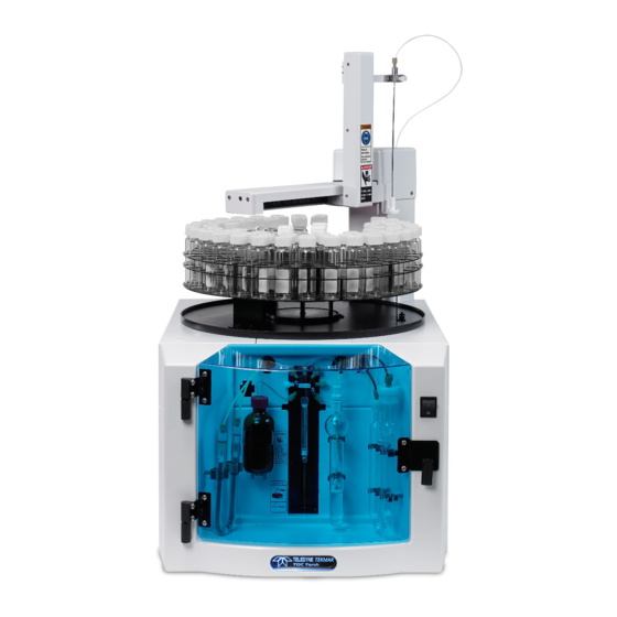
This section briefly describes the individual components of the Torch. Figure 1-1: Front View Figure 1-2: Rear View Banner dIsplay The Banner Display, located at the bottom-front of the instrument, displays a color indicating the current mode of the instrument as shown in the table below:... -
Page 19: Ic Sparger
(mcs) The detector, which measures carbon dioxide, is affected Figure 1-8: Condensing Loop Figure 1-7: Halogen by water vapor, so the Torch is designed to remove Scrubber and Cooling Fan moisture from the sample. The Torch MCS consists of: •... -
Page 20: Non-Dispersive Infrared (Ndir) Detector
Infrared (ndIr) detector After the Torch oxidizes the sample, it is swept into the detector and pressurized to ensure that the entire sample is present. The NDIR detector then measures the concentration of carbon dioxide. The NDIR detector of the Torch is based on proprietary sensing technology. -
Page 21: Mass Flow Controller (Mfc)
The MFC also allows the system to operate without an external step-down pressure regulator. The digital MFC used in the Torch is calibrated to control the flow of the carrier gas (oxygen or TOC-free air). Use of any other gas will cause the MFC to read inaccurately. Be sure to use the specified pressure range as noted in the Utility Requirements section under Regulators. -
Page 22: Autosampler
The Torch has an integrated autosampler with an arm and carousel for position selection. It auto-rinses with sample and/or rinse water via a built-in rinse station. The autosampler has a vertical punch strength of 8.3lbs (3.77 kg). The robotics positioning performance: Accuracy: ±2.5mm... -
Page 23: Chapter 2: Installation & Setup
Chapter 2: Installation & Setup Introduction • Page 1-12 Torch User Manual www.teledynetekmar.com... -
Page 24: Pre-Installation
Before yoU BegIn This section describes how to install the Torch. Installation should be performed in the sequence presented in this section. When all utilities and required facilities have been set up, contact Teledyne Tekmar or its authorized representative to schedule the installation and start-up assistance. -
Page 25: Minimum Computer Requirements
Bench Space The Torch dimensions are 18” W x 24.5” D x 32” H (45.7cm x 62.2cm x 81.3cm) Typical computer dimensions are 18” W x 27” D x 22” H (45.7cm x 68.6cm x 55.9cm) Total recommended bench length is 3’ with a computer placed on either side of the instrument. Please allow additional space if a printer is being used. -
Page 26: Installation
Installation Bench placement Arrange the Torch on the laboratory bench with the glassware facing forward. Allow for generous workspace above and around the analyzer. fUrnace setUp furnace quick disconnect power fitting Remove packing foam before plugging in the Furnace AC connector on the right side baffle wall by the NDIR detector. -
Page 27: Electrical And Data Connections
10. Attach furnace AC quick disconnect fitting. 11. Replace the right side cover. note: Prior to initial Torch operation and each time you install new catalyst, you must condition the catalyst as indicated in the Conditioning the Catalyst section of Chapter 8. -
Page 28: I/O Cable
This is the preferred method of communication. I/o cable The I/O cable allows you to link the Torch to a computer via COM port. Refer to the TOC TekLink Software section of this manual for more information. 1. Locate the I/O cable from the shipping box. -
Page 29: Water, Reagent, And Gas Connections
Make sure the tubing reaches to the bottom of each of the bottles. Specific instructions for connecting the tubing to the reagent bottles are in the sections following. Figure 2-5: Tubing Exit Ports on Rear of Torch exit port labeled “vents”: • Yellow tubing from Permeation Dryer •... -
Page 30: Connecting The Torch To A Di Water Supply
Use water of the quality prescribed in the Materials and Reagents section in the next chapter for proper operation of the Torch. The Torch comes with a 2.4L bottle to use as the DI water reservoir. note: For best results change water on a daily basis. -
Page 31: Connecting The Torch To The Waste Container
Use water of the quality prescribed in the Materials and Reagents section in the next chapter for proper operation of the Torch. The Torch comes with a 2.4L bottle to use as the DI water reservoir. 1. Place a waste container of your choice (not supplied) to the right of and below the unit. -
Page 32: Connecting The Torch To A Gas Supply
Also refer to the respective MSDS for information on specific chemicals. To avoid injury to yourself or damage to the Torch, do not exceed the recommended pressure settings. Observe safety regulations when handling pressurized gas. For more... -
Page 33: Installing The Drain Tray And Carousel
Figure 2-11: Tray Installed To remove the carousel, lift it straight up and pull it towards you. The Torch is now properly installed. After the installation of the TOC TekLink software, the system will be ready for analysis. Move on to the next chapter, which discusses the reagents and standards necessary to complete your first analysis. -
Page 34: Hardware Install Complete
Install complete The Torch is now properly installed. After the installation of the TOC TekLink software, the system will be ready for analysis. Figure 2-14: Install Complete Installation & Setup • Page 2-12 Torch User Manual www.teledynetekmar.com... -
Page 35: Chapter 3: Materials, Reagents, And Standards
Chapter 3: Materials, Reagents & Standards Introduction • Page 1-12 Torch User Manual www.teledynetekmar.com... -
Page 36: Preparing Reagents And Standards
This section has all the preparations and specification of materials needed to run samples on the Torch. materIals and reagents reagent Water (h Common laboratory deionized (DI) water systems produce a wide variation in water quality with respect to carbon content. -
Page 37: Glassware
• Molecular Weight: 84.01 • Percent Carbon: 14.29% • CAS Number: 144-55-8 Teledyne Tekmar offers a variety of concentrations for certified standard solutions. See your local Teledyne Tekmar sales representative for more details. phosphoric acid, concentrated (h • Grade: ACS Reagent •... -
Page 38: Procedure For Glassware Cleaning
Rewashing recontaminates the clean surface with the carbon containing cleaning solution. Instead, begin with step 2 and proceed from there to reclean the glassware. Materials, Reagents & Standards • Page 3-4 Torch User Manual www.teledynetekmar.com... -
Page 39: Preparation Of Reagent Solutions
4. Swirl the flask to dissolve the KHP. 5. Fill the flask to the 1L mark with reagent water. 6. Invert the flask at least five times to homogenize the solution. Materials, Reagents & Standards • Page 3-5 Torch User Manual www.teledynetekmar.com... -
Page 40: Formula For Preparation Of Standards
The typical shelf life for working standard solutions containing less than 1.0ppmC is one week. Higher concentration stock solutions have a shelf life of about one month. Materials, Reagents & Standards • Page 3-6 Torch User Manual www.teledynetekmar.com... -
Page 41: Chapter 4: Toc Teklink Tm Software Setup
Chapter 4: TOC TekLink™ Software Setup Introduction • Page 1-12 Torch User Manual www.teledynetekmar.com... -
Page 42: Toc Teklink Tm Setup Overview
2. Insert the CD into the PC CD drive and wait for the CD Menu to appear. If Autorun is disabled on your PC, open “My Computer” and right-click on the CD-ROM drive letter and select autoplay. 3. With the first item, “Torch TekLink” selected, click the install button. Figure 4-1: Initial Install Screen TOC TekLink Software Setup•... -
Page 43: Installing The Microsoft .Net 2.0 Framework From The Menu
2. Follow the prompts to complete the Microsoft .NET 2.0 Framework install. 3. Once the .NET 2.0 Framework has been installed, skip back to the previous section and install the TOC TekLink™ software. TOC TekLink Software Setup• Page 4-3 Torch User Manual www.teledynetekmar.com... -
Page 44: Instrument Communication
This section will walk you through configuring communications for the computer and the Torch. There are two options for communication: • RS232 (I/O Cable) • TCP/IP (Ethernet Crossover Cable) rS232 connection note: This is the preferred method of connection. - Page 45 Once the IP address has been adjusted, proceed to the Starting TOC TekLink section. Figure 4-7: Local Area Connection Properties Figure 4-8: TCP/IP Properties TOC TekLink Software Setup• Page 4-5 Torch User Manual www.teledynetekmar.com...
-
Page 46: Starting Toc Teklink
The internal PC comes with Windows XP Professional and TOC TekLink preinstalled. The Windows users and corresponding passwords are: • User: Administrator Password: TTTorch9! • User: Torch Password: Torch1 The TOC TekLink users and corresponding passwords are: • User: Administrator Password: TTTorch9! •... -
Page 47: Instrument Tcp/Ip Configuration
Switch 2 open; others closed 192.168.2.121 - 129 Switch 1 & 2 open; others closed 10.0.10.111 - 119 Switch 3 open; others closed 10.0.5.121 – 129 Switch 1 & 3 open; others closed TOC TekLink Software Setup• Page 4-7 Torch User Manual www.teledynetekmar.com... - Page 48 Your PC, including the one provided in the stand-alone version, may not be in the same subnet address as the default values found in the Torch. The instrument will be using a netmask of 255.0.0.0, possibly requiring the PC to temporarily alter its IP address in order to connect and configure the instrument’s IP, subnet, netmask, and MAC...
-
Page 49: Editing Network Settings
Teledyne Tekmar, so there should be no conflict with any other Ethernet equipment currently operating on your LAN. If more than one Teledyne Tekmar instrument is on a network, use a different switch setting when changing network settings. Do not use the same switch setting at a different IP address. -
Page 50: Toc Teklink Basics
If selecting an item with its own submenu such as “Maintenance Tasks”, use the right arrow key to open the submenu. Once you are at the item you want, press enter. TOC TekLink Software Setup• Page 4-10 Torch User Manual www.teledynetekmar.com... -
Page 51: Toc Teklink Tm Help
To access the about teklink screen, click help/about toc teklink. Figure 4-19: About TekLink... -
Page 52: User Account Management
Figure 4-22: Change Password Screen • Selecting the change Password at next login option on the user Properties screen, then logging on again. • Clicking the change Password button on the user Properties screen. TOC TekLink Software Setup• Page 4-12 Torch User Manual www.teledynetekmar.com... -
Page 53: Reset Password
User Permissions section in Chapter 7. comments tab The comments tab displays all the current comments for Figure 4-25: User Properties - Permissions the instrument, and allows for the editing and creation of new comments. TOC TekLink Software Setup• Page 4-13 Torch User Manual www.teledynetekmar.com... -
Page 54: Instrument Management
The Viewing pane shows reports, calibrations, etc. when they are opened or created. Figure 4-26: Main Screen TOC TekLink Software Setup• Page 4-14 Torch User Manual www.teledynetekmar.com... -
Page 55: Toc Teklink Tm Buttons And Menus
TOC TekLink program down. TOC TekLink Software Setup• Page 4-15 Torch User Manual www.teledynetekmar.com... -
Page 56: View Menu
Standby mode and turns OFF all components, except for the NDIR Detector and furnace. If the NDIR Detector or furnace is turned OFF, a minimum of 30 minutes is required for it to stabilize after startup. TOC TekLink Software Setup• Page 4-16 Torch User Manual www.teledynetekmar.com... -
Page 57: Tools Menu
Figure 4-32: Tools - Maintenance Tasks Menu leak check opens a submenu with Furnace Flow path, IC Flow path, or both as selections for choosing what flow path to Leak Check. TOC TekLink Software Setup• Page 4-17 Torch User Manual www.teledynetekmar.com... -
Page 58: Windows Menu
Clicking the filename bring the corresponding file window to the top. help Menu help/contents and index opens the Help Files. help/about torch teklink displays the versions of the software and firmware and displays if the versions have been verified. -
Page 59: Instrument Manager
The help menu contains the following selection: • About TekLink … - opens up a screen that displays the Torch Engine version. The Connect button connects to the selected instrument and opens the Main screen. An instrument must be selected before this menu item is accessible. -
Page 60: Instrument Configuration
The name text box is where you put the official name of the instrument. Model is a drop list that contains instruments that are usable with TOC TekLink™. For this choose the Torch. The location text box is where the description regarding the location of the instrument can be entered. This text box is optional and does not need to be completed. -
Page 61: Configuration Tab
Pressure Delta and allows the user to modify the setting within the bounds displayed to the right of the text box. This setting indicates the maximum allowable change in pressure during Leak Check. TOC TekLink Software Setup• Page 4-21 Torch User Manual www.teledynetekmar.com... -
Page 62: Advanced Tab
This setting is used in conjunction with a control setpoint to monitor and prevent temperature Figure 4-39: Instrument Configuration - Advanced Tab runaway situations. TOC TekLink Software Setup• Page 4-22 Torch User Manual www.teledynetekmar.com... -
Page 63: System Properties
In the event that the archive function is activated while a schedule is running, the archive function will wait until the schedule is complete then close the Main screen to complete the archiving. The Begin archive button starts the archiving process. TOC TekLink Software Setup• Page 4-23 Torch User Manual www.teledynetekmar.com... -
Page 64: Change Justification Tab
The cSV export tab displays the current profile used when the cSV export button is pressed in the Static report screen. This profile can be modified from the Select report fields screen by clicking the edit fields... button. TOC TekLink Software Setup• Page 4-24 Torch User Manual www.teledynetekmar.com... -
Page 65: Diagnostics
The new Setpoint button causes the MFC to change to the setpoint entered into the text box to the right. • The Mixer Speed field displays the speed selected for mixing. TOC TekLink Software Setup• Page 4-25 Torch User Manual www.teledynetekmar.com... -
Page 66: Pumper Tab
Figure 4-47: Diagnostics – Autosampler The Move button causes the corresponding component to move to the position designated in the destination field. The home Motors button commands the Torch to move all of the autosampler parts to their home locations. TOC TekLink Software Setup•... -
Page 67: Benchmark Tab
Solenoid Valves: In this test the Torch verifies the function of each valve. It turns on a valve, which activates the light on the valve and the Motor Control Board. A successful test has occurred when a LED is lit on the valve and the board. -
Page 68: Analogue Board Tab
TN Offset, Reset, Start, Stop, E-Test, O-Test, and HI-Gain buttons. firMware uPdate To upgrade the firmware follow the instructions below: 1. Go to the Teledyne Tekmar Website (www.teledynetekmar.com) and download the latest firmware version. 2. Click tools/update firmware to open the update Figure 4-50: Firmware Update Screen firmware screen. -
Page 69: Calibration Editor
Method: The linear y=m(x)+b method calculates the curve from the selected calibration points. coefficient of correlation: This is a calculated value to show how well the trend line has fit the calibration points. TOC TekLink Software Setup• Page 4-29 Torch User Manual www.teledynetekmar.com... -
Page 70: Method Editor
Sweep time (min): The total time the furnace is being swept. This variable can be modified within the range of 0.0-60.0min. System flow (ml/min): The flow rate of the carrier gas in the system. This variable can be modified within the range of 0-500mL/min. TOC TekLink Software Setup• Page 4-30 Torch User Manual www.teledynetekmar.com... -
Page 71: Advanced Tab
Syringe Speed furnace aspirate: The speed that the syringe moves to aspirate sample to the Furnace. This variable can be modified within the range of 1-10. furnace temperature (°c): The temperature setpoint of the furnace. This variable can be modified within the range of 600-1000°C TOC TekLink Software Setup• Page 4-31 Torch User Manual www.teledynetekmar.com... -
Page 72: Comments Tab
• System Suitability – These standards are used to verify that the instrument’s ability to produce accurate and precise results. options tab The options tab has a linear tab which gives options for acceptance criteria for Check Standard results in the Linear mode. TOC TekLink Software Setup• Page 4-32 Torch User Manual www.teledynetekmar.com... -
Page 73: Schedule Editor
• Select all rows, which highlights all of the lines in the schedule. • invert row Selection, which inverts the selected rows. • insert line, which inserts a blank line above/below the selected row. • delete line, which deletes the selected line. TOC TekLink Software Setup• Page 4-33 Torch User Manual www.teledynetekmar.com... -
Page 74: Samples Tab
Maximum number of auto rinses Before re-Sampling - This variable allows the user to select the number of DI water reps to run before re-sampling due to an out-of-range sample. TOC TekLink Software Setup• Page 4-34 Torch User Manual www.teledynetekmar.com... -
Page 75: Comments Tab
Blank version for the method, a button to view the history of the version, a Details field, a Comments text box, and buttons for printing. Figure 4-58: Instrument Blank Screen TOC TekLink Software Setup• Page 4-35 Torch User Manual www.teledynetekmar.com... -
Page 76: Report
The available types of export formats are HTML, XML, and CSV. You can choose to print the reports rather than export them. TOC TekLink Software Setup• Page 4-36 Torch User Manual www.teledynetekmar.com... -
Page 77: Interactive Tab
To import a calibration from the instrument, click the down arrow icon of the edit calibration button, select import calibration from the instrument from the drop list, click the edit calibration button, and select the new calibration from the screen that appears. TOC TekLink Software Setup• Page 4-37 Torch User Manual www.teledynetekmar.com... - Page 78 Each report can have multiple signatures. Signing a report does not cause file/Save to become accessible because an electronic signature is automatically saved to the report upon finishing the signing process. TOC TekLink Software Setup• Page 4-38 Torch User Manual www.teledynetekmar.com...
-
Page 79: Chapter 5: Optional Total Nitrogen Module
Chapter 5: Optional Total Nitrogen Module Introduction • Page 1-12 Torch User Manual www.teledynetekmar.com... -
Page 80: Tn Analysis Overview
Module Figure 5-1: Torch with Total Nitrogen Module Figure 5-1 shows the main Torch unit with the TN Module. The Nitrogen Module sits to the left of the Torch and is comprised of the following: • Ozone generator •... - Page 81 (hv). This process is known as chemiluminescence. A lightdetecting device converts the light signal to an electronic signal that allows quantitation. Torch employs a chemiluminescence detector using a photomultiplier tube. The amount of light detected is directly proportional to the amount of NO in the sample gas. The resulting integrated area is then compared to stored calibration data and a sample concentration in parts-per-million (ppm) is reported.
-
Page 82: Technical Specifications
Module EN-12260 DIN-EN-ISO 11905-2 EPA 415.1 and 9060A Standard Method 5310B ASTM D2579 ISO 8245 AOAC 973.47 Cleaning Validation USP 643 Drinking/Surface Water Industrial Waste Effluent Waste Water Sea Water Optional Total Nitrogen Module• Page 5-4 Torch User Manual www.teledynetekmar.com... -
Page 83: Component Overview
CD cells. When enough high-energy electrons are produced to ionize the oxygen molecules, a light emitting, gaseous plasma is formed, which is commonly referred to as a corona, hence the name corona discharge generator. Optional Total Nitrogen Module• Page 5-5 Torch User Manual www.teledynetekmar.com... -
Page 84: Photomultiplier Tube
Sample gas swept through corrosives scrubber Sample gas swept into NDIR for SPC measurement Memorize CLD threshold Sample gas swept through CLD Nitrogen concentration is measured Excess water in trap is emptied to waste Optional Total Nitrogen Module• Page 5-6 Torch User Manual www.teledynetekmar.com... -
Page 85: Total Organic Carbon With Total Nitrogen (Toc/Tn)
Sample gas swept through corrosives scrubber Sample gas swept into NDIR for SPC measurement Memorize CLD threshold Sample gas swept through CLD Nitrogen concentration is measured Excess water in trap is emptied to waste Optional Total Nitrogen Module• Page 5-7 Torch User Manual www.teledynetekmar.com... -
Page 86: Installation
Bench PlaceMent Position the Nitrogen Module to the left of the Torch. You may also wish to place a local or network printer near the computer for printing data reports. Allow for generous work space around and above the analyzer. -
Page 87: Connect Oxygen Supply To Ozonator
This section and the four following give instructions for upgrading the Torch to a Torch with Total Nitrogen. If you are installing a Torch with Total Nitrogen, rather than upgrading an existing Torch unit, these changes have already been made. If this is the case, make the gas and power connections to install the Nitrogen module and verify the following flows: •... -
Page 88: Make Plumbing Alterations
Make Plumbing alterations Disconnect the plug from the poly tee nearest the Torch’s valve A COM port and connect the tubing from the TN’s valve D NC port. • Disconnect the tin side of the halide scrubber and connect to the TN valve D COM port. -
Page 89: Preventative Maintenance
• inspect Permeation dryer – Inspect for damage and water accumulation. Replace the Permeation Dryer if there is evidence of significant damage. note: The Consumables Kit includes most items for the Torch. Optional Total Nitrogen Module• Page 5-11 Torch User Manual... -
Page 90: Preventive Maintenance Chart
Flush Sample Transfer Line Initials & Date Daily & Monthly Maintenance Items Permeation Dryer: Inspect for damage and water accumulation Inspect Combustion Tube Monthly Inspect Catalyst, Sleeve, Screen, and Needle Initials & Date Optional Total Nitrogen Module• Page 5-12 Torch User Manual www.teledynetekmar.com... -
Page 91: Replacing Parts
7. Disconnect the four (4) Keep nuts that hold the detector to the chassis. Note the ground cable location. Disconnect the (3) screws that hold the detector to the chassis. Optional Total Nitrogen Module• Page 5-13 Torch User Manual www.teledynetekmar.com... -
Page 92: Chapter 6: Tutorial
Chapter 6: Tutorial Torch User Manual www.teledynetekmar.com... -
Page 93: Software Tutorial
The instrument Manager screen should now display details of the instrument that we have just finished configuring for communication. 1. Ensure the instrument power is ON. If not turn the power to ON, restart TOC TekLink™ after the Torch has been ON for at least 15 seconds. -
Page 94: Toc Teklink Tm Main
3. The Save as screen will open and you will be prompted to name your calibration file. In the Save as name text box enter “Test Calibration” and click the Save button. Figure 6-3: New Calibration Save As Screen Tutorial • Page 6-3 Torch User Manual www.teledynetekmar.com... -
Page 95: Creating A New Method
3. On the first screen of the Standards editor Wizard, make the following entries in the appropriate section: • Standard ID (Name): 20ppmC KHP • Standard Type: Calibration Standard • Source: Stock Tutorial • Page 6-4 Torch User Manual www.teledynetekmar.com... - Page 96 To delete a line, select the line to be deleted and press the delete key on the keyboard. Alternatively, you can clear the option box in the line, which will instruct the software to ignore it. It should look like: Figure 6-7: Standards Editor Wizard – Step 2 Tutorial • Page 6-5 Torch User Manual www.teledynetekmar.com...
-
Page 97: Creating A New Schedule
• When the Std Editor is displayed, select the newly created 20ppmC kHP std and click the Select button. • Reps: 3 • Position: A note: This step causes lines 4 and 5 to be automatically filled in. Tutorial • Page 6-6 Torch User Manual www.teledynetekmar.com... - Page 98 6. On line 8, select Sample for the sample type. • Position: 2 • Sample ID: Sample 01 • Reps: 3 7. Repeat the previous step, incrementing the position and sample ID, with as many samples as desired. Tutorial • Page 6-7 Torch User Manual www.teledynetekmar.com...
-
Page 99: Running The Schedule
When everything is in order click the Ready button. 2. Make sure the Status Light at the bottom, front of the Torch is blue. A blue Status Light indicates that the instrument detects Figure 6-11: Blue Status Light no problems and has successfully entered the ready mode. -
Page 100: Review
In the event an error has occurred, you may attempt to fix the problem yourself if you feel it is within your ability. For persistent errors, contact the Teledyne Tekmar Customer Support Center. RevieW... -
Page 101: Exporting A Report
3. When the Save as screen appears, click Save to use the default Save As Name or change the name and click Save. This HTML file can be opened by any computer with HTML capabilities. For more information about reports, review the Reports section in Chapter 4. Tutorial • Page 6-10 Torch User Manual www.teledynetekmar.com... -
Page 102: Chapter 7: 21 Cfr 11 Compliance
Chapter 7: 21 CFR 11 Compliance Torch User Manual www.teledynetekmar.com... -
Page 103: 21 Cfr 11 Features And Compliance Tools
The following options from the user Manager screen are user-selectable: • View the current list of accounts defined in TOC TekLink™ • Create new users • View and edit properties of user accounts 21 CFR 11 Compliance • Page 7-2 Torch User Manual www.teledynetekmar.com... -
Page 104: Setting Up User Accounts
Disable instruments: User can enable/disable instruments. electronic Report Signature: User is allowed to verify and sign off on reports. Figure 7-3: User Properties - Permissions Tab 21 CFR 11 Compliance • Page 7-3 Torch User Manual www.teledynetekmar.com... -
Page 105: Edit An Existing Account
If the user does not need to log back in, then another user may click the Change user button to return to the Login screen. Figure 7-5: Automatic Logout Screen 21 CFR 11 Compliance • Page 7-4 Torch User Manual www.teledynetekmar.com... -
Page 106: Lockout
Figure 7-6: System Properties Screen Figure 7-7: System Lockout: Time-out When a user is disabled, the screen below will appear when they try to log in. Figure 7-8: User Disabled 21 CFR 11 Compliance • Page 7-5 Torch User Manual www.teledynetekmar.com... -
Page 107: Data Versioning, History, And Archive
5. When the electronic Signature Reason screen is displayed: • Enter a reason in the Reason for Signature field • Make a selection from the acceptance drop list. 6. Click the Sign button. 21 CFR 11 Compliance • Page 7-6 Torch User Manual www.teledynetekmar.com... - Page 108 7. Enter your Username and Password on the Signature verification screen and click Login. Figure 7-11: Signature Verification Screen The signature is now displayed on the electronic Signature screen. Figure 7-12: Signature Displayed 21 CFR 11 Compliance • Page 7-7 Torch User Manual www.teledynetekmar.com...
-
Page 109: View/Print System History And Error Logs
The apply button refreshes the log and filters out the information as directed by the selections. The Reset button returns the filter selections to their default settings. 21 CFR 11 Compliance • Page 7-8 Torch User Manual www.teledynetekmar.com... -
Page 110: Change Justification
The list of change justifications can be modified in the System Properties screen Change Justifications tab. See the System Properties Change Justification section for more information. Figure 7-14: Change Justification Screen 21 CFR 11 Compliance • Page 7-9 Torch User Manual www.teledynetekmar.com... -
Page 111: Chapter 8: System Operations
Chapter 8: System Operations Torch User Manual www.teledynetekmar.com... -
Page 112: System Operations
System operations This section outlines how to set up the Torch for analysis. Instrument preparation, calibration, method, schedule and sample setup are discussed. For illustration purposes, the setups in the examples are typical for analysis of wastewater and industrial effluents. However, these concepts can also be applied to a variety of other applications such as: drinking water, surface water, ground water, seawater, brines, and certain Clean-in-Place applications. -
Page 113: Understanding The Analysis Types
THe anaLySiS TyPeS The Torch has four analysis types: • Total Organic Carbon (TOC) • Total Carbon (TC) • Inorganic Carbon (IC) • Total Carbon Minus Inorganic Carbon (TC-IC) This section covers sample introduction and presents event flow diagrams for each of the four analysis types. -
Page 114: Sample Introduction
For example, if you are testing a 0.5mL sample, more than 0.5mL is aspirated into the syringe. The Torch expels some of the sample to waste, delivers the next 0.5mLs to the furnace or IC Sparger then expels the remaining sample to waste. -
Page 115: Total Organic Carbon (Toc)
NDIR for detection. NDIR signal is sent to the computer for analysis. Furnace injection line is emptied to waste. Furnace injection line is rinsed with water then water is sent to waste. Return to Step 1 for additional replicates. System Operations • Page 8-5 Torch User Manual www.teledynetekmar.com... -
Page 116: Inorganic Carbon (Ic)
TC, the other to measure IC. The difference between these two measurements is the TOC result. SySTeM CLean When creating a new schedule, selecting “clean” from the sample type drop down menu will prompt the Torch to run an automated cleaning procedure when the corresponding schedule line is started. The cleaning procedure ensures sample pathway cleanliness by first rinsing the IC sparger and then rinsing the furnace injection line three times. -
Page 117: Calibration
Before analyses, the Torch must be calibrated in which the calibration slope (m) and y-intercept (b) are created. A calibration slope correlates the detector response (adjusted absorbance) of the instrument to a known amount of carbon (x) in the standard. -
Page 118: Methods
(?) Question mark Figure 8-4: Method Editor Running an improperly setup method may damage the Torch. Setting up a new method should be performed by personnel who are properly trained, knowledgeable, and well acquainted with the Torch. The analysis method contains all the parameters pertinent to analysis such as sample volume, dilution ratio, and sparge time for the IC Sparger. -
Page 119: Selecting The Correct Methods
Correct method selection is critical to obtaining good analytical results. For new users, Teledyne Tekmar recommends using one of the default methods within TOC TekLink™ software. For the vast majority of Torch users, TOC will be the analysis of interest. -
Page 120: Schedule Setup
The Method Editor allows changing and adjusting many parameters that will optimize the instrument’s performance for a wide variety of sample types. Follow the guidelines in the Method Editor section of Chapter 4: TOC Teklink Software Setup. System Operations • Page 8-10 Torch User Manual www.teledynetekmar.com... -
Page 121: Special Applications
HCl is a problem. The HCl is removed from the gas stream using copper and tin granules inside a halide scrubber. However, in some cases the HCl may break through and cause the detector to become corroded. The Torch uses an NDIR sample cell which is constructed of a non-corrosive material that eliminates this problem. nitric acid (Hno Nitric acid typically has a higher level of carbon contamination, resulting in higher blanks. -
Page 122: Applications
Low-level Carbon The high sensitivity and precision of the Torch make it ideal for low-level TOC analysis. However, several issues must be taken into account when running low carbon samples: Clean the Glassware We recommend that all glassware be cleaned with soap and hot water, followed by triple rinsing with deionized (DI) water. -
Page 123: Chapter 9: Maintenance & Troubleshooting
Chapter 9: Maintenance & Troubleshooting Torch User Manual www.teledynetekmar.com... -
Page 124: Preventive Maintenance Checklist
DaiLy MainTenanCe CHeCkS • Gas Supply - Verify the gas source is supplying an input pressure of 65-100psi (4.5 - 6.9bar) to the Torch. If you are using a gas cylinder, verify the cylinder is at 500+psi (34.5+bar). If not, replace the cylinder. -
Page 125: Preventive Maintenance Chart
Flush Sample Transfer Line initials & Date Daily & Monthly Maintenance items Permeation Dryer: inspect for damage and water accumulation inspect Combustion Tube Monthly inspect Catalyst, Sleeve, Screen, and needle initials & Date Maintenance & Troubleshooting • Page 9-3 Torch User Manual www.teledynetekmar.com... -
Page 126: Replacing Parts
Optical Sample Positioning Mixer Sensor 3-way Valves Furnace Pressure NDIR Regulator Detector Perm Dryer Figure 9-3: Plumbing Side of Torch (Right) Motor Control 24VDC Power Supply Control 5VDC Power Analog Supply 12VDC Power Figure 9-4: Electronics Side of Torch (Left) Supply Maintenance &... -
Page 127: Combustion Tube And Catalyst
• Tube packing tool • Vacuum grease Removing the Combustion Tube 1. Turn OFF power to the Torch and remove the AC power line from the back of the instrument. 2. Remove the right side cover of the instrument and slide the furnace chamber out towards the right side. -
Page 128: Installing A New Combustion Tube
• 1/16” (0.16cm) tubing cutter Making a 1/2mL Injection Line Needle 1. Open the front hood of the Torch and disconnect the Acid line from position F on the 7-port Valve. 2. Place the 7-port Valve in the Acid position (F) using the Diagnostic screen in TOC TekLink . -
Page 129: Replacing The Injection Line Needle
10. Close the hood. Replacing the Injection Line Needle 1. Turn OFF power to the Torch and remove the AC Power Line from the back of the instrument. 2. Remove the right side cover and open the front hood. 3. Allow the furnace to cool. -
Page 130: Furnace / Tc Probe
TC Probes • 5/16” (0.79cm) nut driver • Wire ties 1. Turn OFF power to the Torch and remove the AC Power Line from the back of the instrument. 2. Remove the right side cover. 3. Allow the furnace to cool completely. -
Page 131: Furnace Fans
• Phillips screwdriver • 5/16” (0.79cm) nut driver • Wire ties 1. Turn OFF power to the Torch and remove the AC Power Line from the back of the instrument. 2. Remove the right side cover, carrousel, drain tray, and top cover. -
Page 132: Mist Trap
The Pyrex wool at the bottom of the Halogen Scrubber may be replaced at this time. When replacing Pyrex wool, it must be loosely packed to avoid excessive back pressure. Maintenance & Troubleshooting • Page 9-10 Torch User Manual www.teledynetekmar.com... -
Page 133: Permeation Dryer
4. Reattach the Halogen Scrubber to the front of the instrument and close the hood. PeRMeaTion DRyeR Tool Required: • Phillips screwdriver (to remove the Torch cover) • Flathead screwdriver • Razor blade 1. Remove the right side cover and locate the Permeation Dryer (See Figure 9-3). -
Page 134: Autosampler Needle
Your first pull could contain dead volume from the sample line. By dispensing syringe pulls to the waste port and pulling again from the sample port, you should be able to verify proper performance. Maintenance & Troubleshooting • Page 9-12 Torch User Manual www.teledynetekmar.com... -
Page 135: 7-Port Valve
Make sure that the fitting and ferrule are separated to prevent the line from twisting when reinstalling. The 1/16” (0.16cm) fittings are special fittings and line twisting is not an issue. Maintenance & Troubleshooting • Page 9-13 Torch User Manual www.teledynetekmar.com... - Page 136 DI water port. You should see liquid enter the syringe. 15. Close the door. 16. Click Tools/Maintenance Tasks/Prime System. This ensures that the acid and DI water lines are properly primed and the system is ready for analysis. Maintenance & Troubleshooting • Page 9-14 Torch User Manual www.teledynetekmar.com...
-
Page 137: 3-Way Valve
The following tools are required to remove a 3-Way Valve: • Slotted screwdriver • Phillips screwdriver 1. Turn OFF the power to the Torch and remove the AC power line from the back. 2. Remove the right side cover and locate the 3-way Valve to be replaced (See Figure 9-3). -
Page 138: Dc Control Pcb
The following tools are required to remove the Analog Board: • Phillips screwdriver • Flathead screwdriver 1. Turn OFF power to the Torch and remove the AC Power Line from the back of the instrument. 2. Remove the left side cover. 3. Locate the Analog board. -
Page 139: Fuse
The following tools are required to remove the PEM: • Phillips screwdriver 1. Turn OFF the power to the Torch and remove the AC Power Line from the back of the instrument. 2. Remove the left side cover. 3. Note the location of and disconnect all of the electrical connections from the PEM. -
Page 140: 5Vdc Power Supply
The following tools are required to remove the 5VDC Power Supply: • Phillips screwdriver • Flathead screwdriver 1. Turn OFF power to the Torch and remove the AC power line from the back of the instrument. Figure 9-27: 5VDC Power Supply 2. Remove the left side cover. -
Page 141: 24Vdc Power Supply
• Flathead screwdriver Figure 9-29: 24VDC Power Supply 1. Turn OFF power to the Torch and remove the AC power line from the back of the instrument. 2. Remove the left side cover. 3. Locate the Power Supply. It is the 7.5” x 4” (19.05cm x 10.16cm) PCB on the middle panel, located towards the middle of the instrument (See Figure 9-4). -
Page 142: Mass Flow Controller (Mfc)
• Phillips screwdriver • Slotted screwdriver • 7/16” (1.11cm) open end wrench (pair) 1. Turn OFF the power to the Torch and remove the AC Power Line from the back of the instrument. Figure 9-30: Mass Flow Controller 2. Remove the right side cover. -
Page 143: Ndir Detector
• 7/16” (1.11cm) open end wrench (pair) Figure 9-32: NDIR Detector 1. Turn OFF the power to the Torch and remove the AC Power Line from the back of the instrument. 2. Remove the right side cover. 3. Locate the NDIR Detector (See Figure 9-3) and disconnect the electrical connection from the NDIR Detector. -
Page 144: Pressure Regulator
PReSSuRe ReguLaToR To avoid electrical shock, turn OFF and unplug the Torch before servicing. The following tools are required to remove the Pressure Regulator: • Phillips screwdriver • 7/16” (1.11cm) open end wrench (pair) • Channel Lock Pliers Figure 9-33: Pressure Regulator 1. -
Page 145: Leak Checking The Torch
Leak Checking the Torch Leak Checking should be performed daily, or if you detect abnormal performance from the instrument. You can perform a Leak Check using the TOC TekLink soft- 7-port ware. The Leak Check options are accessible by clicking... - Page 146 NDIR Detector, and install a cap nut. Perform a manual Leak Check. If a leak is observed, the NDIR Detector has an internal leak and must be replaced. Maintenance & Troubleshooting • Page 9-24 Torch User Manual www.teledynetekmar.com...
-
Page 147: Ic Flow Path
A system is considered leak tight if the decrease in pressure is less than 0.1psi/15 seconds. If a leak is observed, check the IC Sparger cap fittings and o-rings and the fitting at port on the 7-port Valve. To release the pressure, activate Valve E. Maintenance & Troubleshooting • Page 9-25 Torch User Manual www.teledynetekmar.com... -
Page 148: Troubleshooting The Torch
3. Place the manual and any other pertinent information next to a telephone. Your service representative may refer to diagrams or other information contained in your manual. 4. Call Teledyne Tekmar: TeLeDyne TekMaR CuSToMeR SuPPoRT CenTeR: • (800) 874-2004 in the u.S. and Canada • Country Code +1 (513) 229-7000 outside the u.S. and Canada Maintenance &... -
Page 149: Arm Adjustment
To avoid electrical shock, turn OFF and unplug the Torch before servicing. If the Needle is off-center to the Rinse Station follow the directions below: Solution 1: Adjust the Rinse Station 1. Loosen the 1” (2.54cm) hex nut directly underneath the Rinse Station on the inside of the instrument. -
Page 150: Troubleshooting Chart
TroubleShooTing CharT Symptoms Possible Cause(s) Solution(s) Poor results and/or Low recovery Torch not pressurizing properly or not Refer to the Isolating a Leak section in on Check Standards. maintaining pressure once pressurized. the Manual. Instrument does not respond to The connection between the Torch and Reboot the entire system. -
Page 151: Returning The Torch
ReTuRning THe ToRCH Do not return the Torch unless a Teledyne Tekmar representative authorizes you to do so. A service representative may be able to help you solve the problem over the telephone. If the instrument must be returned, the representative can tell you how to prevent damage during shipment. -
Page 152: Chapter 10: Glossary
Chapter 10: Glossary Torch User Manual www.teledynetekmar.com... -
Page 153: Acronyms
- Suspended Organic Carbon Tc – Total Carbon Toc – Total Organic Carbon TIc - Total Inorganic Carbon UsP – United States Pharmacopoeia UV – Ultra Violet WFI – Water For Injection Glossary • Page 10-2 Torch User Manual www.teledynetekmar.com... -
Page 154: Terms
- The procedure, or sequence of steps and parameters, used in analysis. mode - The type of analysis (TC, TOC, IC, TC-IC). Nondispersive Infrared Detector (NDIr) - This is a measuring instrument that provides electrical signal proportional to the concentration of carbon dioxide. Glossary • Page 10-3 Torch User Manual www.teledynetekmar.com... - Page 155 Total carbon (Tc) - This is all the carbon in the sample, including both inorganic and organic carbon. Total Inorganic carbon (TIc) - See inorganic carbon Total organic carbon (Toc) - See organic carbon Vial – A small container, usually with a closure, used especially for liquids. Glossary • Page 10-4 Torch User Manual www.teledynetekmar.com...
-
Page 156: Chapter 11: Diagrams
Chapter 11: Diagrams Torch User Manual www.teledynetekmar.com... -
Page 157: Electrical Schematic - Torch
Electrical schematic - Torch note: Be aware that part numbers may have changed since the publication of this manual. Please contact technical support for current part number listing and pricing. Diagrams • Page 11-2 Torch User Manual www.teledynetekmar.com... -
Page 158: Electrical Schematic - Tn Module
Electrical schematic - Tn module note: Be aware that part numbers may have changed since the publication of this manual. Please contact technical support for current part number listing and pricing. Diagrams • Page 11-3 Torch User Manual www.teledynetekmar.com... -
Page 159: Torch Flow Diagrams - Basic
Torch Flow Diagrams - Basic Diagrams • Page 11-4 Torch User Manual www.teledynetekmar.com... -
Page 160: Dispense Acid
Dispense Acid Diagrams • Page 11-5 Torch User Manual www.teledynetekmar.com... -
Page 161: Dispense Sample To Ic Sparger
Dispense sample to Ic sparger Diagrams • Page 11-6 Torch User Manual www.teledynetekmar.com... -
Page 162: Drain Mode
Drain mode Diagrams • Page 11-7 Torch User Manual www.teledynetekmar.com... -
Page 163: Ic Sparge
Ic sparger Diagrams • Page 11-8 Torch User Manual www.teledynetekmar.com... -
Page 164: Pressurize Furnace
Pressurized Furnace Diagrams • Page 11-9 Torch User Manual www.teledynetekmar.com... -
Page 165: Pull Acid
Pull Acid Diagrams • Page 11-10 Torch User Manual www.teledynetekmar.com... -
Page 166: Pull Sample
Pull sample Diagrams • Page 11-11 Torch User Manual www.teledynetekmar.com... -
Page 167: Pull Sparged Sample
Pull sparged sample Diagrams • Page 11-12 Torch User Manual www.teledynetekmar.com... -
Page 168: Sample Inject
Inject Diagrams • Page 11-13 Torch User Manual www.teledynetekmar.com... -
Page 169: System Sweep
Diagrams • Page 11-14 Torch User Manual www.teledynetekmar.com... -
Page 170: Torch & Tn Flow Diagrams - Basic
Torch & Tn Flow Diagrams - Basic Diagrams • Page 11-15 Torch User Manual www.teledynetekmar.com... -
Page 171: Tn Sample Flow
Tn sample Flow Diagrams • Page 11-16 Torch User Manual www.teledynetekmar.com... -
Page 172: Index
Index Torch User Manual www.teledynetekmar.com... - Page 173 ................1 - 7 First Login Acid Container ..............1 -12 External PC ..............4 - 6 Autosampler ..............1 - 13 Internal PC ..............4 - 6 Flow Restrictors ............1 - 11 Halogen Scrubber ............1 - 10 Torch User Manual www.teledynetekmar.com...
- Page 174 Overview ...............1 - 10 Waste ................2 - 9 moisture control system Installing .nET 2.0 Framework ........4 - 3 Overview ...............1 - 10 Installing the Tray and carousel ........2 - 11 motor control PcB ............9 - 15 Torch User Manual www.teledynetekmar.com...
- Page 175 Preventive maintenance checklist ......9 - 2 Extension Cord Warning ..........1 - 4 Daily Maintenance Checks........9 - 2 Lifting the Torch ............1 - 4 Monthly Maintenance Checks ......... 9 - 2 Pressure Settings ............1 - 4 Preventive Maintenance Chart........
- Page 176 User Account Management ........... 4 - 12 Adding a New Instrument ........4 - 9 Add New User ............. 4 - 12 Basics ................4 - 10 Change Password ..........4 - 12 About ..............4 - 11 Torch User Manual www.teledynetekmar.com...
- Page 177 Returning the Torch ..........9 - 27 Water, reagent, and Gas connections ...... 2 - 7 Troubleshooting Chart ..........9 - 28 What is the Torch? ............... 1 - 7 Windows menu ..............4 - 18 Working safely ..............1 - 4 Understanding Analysis Types ........8 - 3 Inorganic Carbon (IC)..........
Need help?
Do you have a question about the Torch and is the answer not in the manual?
Questions and answers