Table of Contents
Advertisement
Quick Links
CCD COLOR CAMERA
IK-VR01A
Please read this manual thoroughly before use, and keep it handy
for future reference.
TABLE OF CONTENTS
1. Features & Description ................................................. 3
2. Cautions ........................................................................ 3
3. Components ................................................................. 3
4. Part Names & Functions ............................................... 4
5. Connections and Operations ........................................ 5
6. Installations ................................................................... 7
7. Line Lock Phase ........................................................... 12
8. Note on use and Installation ......................................... 12
9. In Case of Problems ..................................................... 13
10. Specifications ................................................................ 14
11. Exterior View ................................................................. 15
INSTRUCTION MANUAL
Record in space provided below the Model No. and
the Serial No. as found on the label on the bottom
of this unit.
Model. No. IK-VR01A Serial No.
Retain this information for future reference.
Advertisement
Table of Contents

Related Manuals for Toshiba IK-VR01A


Summary of Contents for Toshiba IK-VR01A
-
Page 1: Table Of Contents
11. Exterior View ... 15 INSTRUCTION MANUAL Record in space provided below the Model No. and the Serial No. as found on the label on the bottom of this unit. Model. No. IK-VR01A Serial No. Retain this information for future reference. -
Page 2: Important Safeguards
IMPORTANT SAFEGUARDS 1. Read Instructions All the safety and operating instructions should be read before the product is operated. 2. Retain Instructions The safety instructions and instruction manual should be retained for future reference. 3. Heed Warnings All warnings on the product and in the instruction manual should be adhered to. - Page 3 CAUTION TO REDUCE THE RISK OF ELECTRIC SHOCK. DO NOT REMOVE COVER (OR BACK). NO USER SERVICEABLE PARTS INSIDE. REFER SERVICING TO QUALIFIED SERVICE PERSONNEL. The lightening flash with arrowhead symbol, within an equilateral triangle, is intended to alert the user to the presence of uninsulated “dangerous voltage”...
-
Page 4: Features & Description
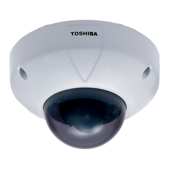
1. FEATURES & DESCRIPTION IK-VR01A has the following features: (1) Flush/Surface mount. (2) IP66 Standard for dust and water resistance. (3) Built in vari-focal lens with auto-iris Focal length 3.0~8.0mm. (4) Incorporated 1/3" type CCD image sensor gives high resolution and excellent... -
Page 5: Part Names & Functions
4. PART NAMES & FUNCTIONS Mode Setting Switch BLC (Backlight Compensation Switch) With the switch on, it adjusts the backlight automatically to obtain the best possible image. Sets camera synchronization to line lock with the switch on. Available only with AC24V. Lens Iris ADJ Counterclockwise: The picture becomes darker. -
Page 6: Connections And Operations
Since this camera uses 24V AC UL Listed Class 2 power supply or 12V DC power supply, it should be connected to a power supply that allows for at least 5w consumption. Because the IK-VR01A uses a mechanism, a sufficient power supply with adequate current specifications is required. - Page 7 5-2 Line-Lock Control • Matching the vertical synchronization with the power frequency is called the Line- Lock. • This function is activated when the LL of Mode Setting Switch is on. • When two or more cameras are switched by the video switcher for viewing by a monitor TV, the vertical sync.
-
Page 8: Installations
6. INSTALLATIONS • Connect the cable of the camera and the cable from the designated power supply with respective connectors. • Screws for fixing the camera and mounting base to the ceiling or wall are not supplied with the unit. Use appropriate screws. Note : •... - Page 9 Tilt rotation Horizontal rotation Pan Lock Remove three silver screws transport protection. Transport Protection Screws (silver) (2) The lens direction in pan direction can be adjusted by turning pan lock 1 counterclockwise to unfasten it without moving the lens. After adjustment, turn pan lock 1 clockwise to fasten it.
- Page 10 6-2 Installing the Camera Unit 6-2-1 Installation to Wall or Ceiling with Mounting Base (Surface Mount Installation) • When installing the camera unit on the wall, mount it with the drain groove on the downside. Do not block the drain groove.
- Page 11 6-2-2 Installation to Junction Box with Bracket (Flush Mount Installation) Screws (not supplied) Screws Mount camera base with three supplied screws B. (Shorter screw(M4x10)) Tighten and lock the screws firmly. 4 6 m m Junction Box 8 3 . 5 m m Bracket Note the direction of the bracket, which has...
- Page 12 6-2-3 Change of Dome Cover Dome replacement When the dome cover is damaged or to be replaced by a transparent cover, call your distributor or sales person. Firmly tighten three mounting screws. Take care not to let dirt or foreign object enter between the parts.
-
Page 13: Line Lock Phase
7. LINE LOCK PHASE When a video switcher switches two or more cameras, the picture may fluctuate on the video monitor due to the different AC line phase of each camera. In this case, adjust the V PHASE controller to get a stable image. Line Lock V PHASE CONTROL 8. -
Page 14: In Case Of Problems
9. IN CASE OF PROBLEMS Condition No image • Are the camera and connected equipment turned on? • Are cables connected correctly? Unnatural color • Is the monitor TV adjusted correctly? • Is the lighting too weak? The image is out of •... -
Page 15: Specifications
10. SPECIFICATIONS 1. Image System Image Device Pixel Elements 2. Electrical TV System Horizontal Resolution S/N Ratio Minimum Illumination Auto Gain Control (AGC) Iris Control Mode White Balance White Balance Range Line lock Vertical phase adjustment Gamma compensation Backlight Compensation (BLC) Video Output Signal Synchronization System 3. -
Page 16: Exterior View
11. EXTERIOR VIEW unit : mm 48.5 - 15 -... - Page 17 unit : mm 61.5 147.5 - 16 -...
- Page 18 Bracket unit : mm 4-M4 Mounting Base 4-M6 Depth=10 - 17 -...
- Page 19 - 18 -...
Need help?
Do you have a question about the IK-VR01A and is the answer not in the manual?
Questions and answers