Table of Contents
Advertisement
Quick Links
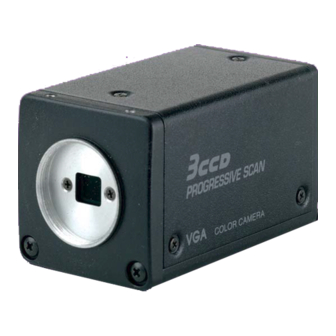
3 CCD CAMERA
IK-TF5
INFORMATION
This equipment has been tested and found to comply with the limits for a Class A digital device, pursu-
ant to Part 15 of the FCC Rules. These limits are designed to provide reasonable protection against
harmful interference when the equipment is operated in a commercial environment. This equipment
generates, uses, and can radiate radio frequency energy and, if not installed and used in accordance
with the instruction manual, may cause harmful interference to radio communications. Operation of this
equipment in a residential area is likely to cause harmful interference in which case the user will be
required to correct the interference at his own expense.
USER-INSTALLER CAUTION: Your authority to operate this FCC verified equipment could be voided if
you make changes or modifications not expressly approved by the party responsible for compliance to
Part 15 of the FCC Rules.
This Class A digital apparatus complies with Canadian ICES-003.
Cet appareil numérique de la classe A est comforme à la norme NMB-003 du Canada.
INSTRUCTION MANUAL
For Customer Use
Enter below the Serial No.
w h i c h i s l o c a t e d o n t h e
bottom of the cabinet. Retain
this information for future ref-
erence.
Model No.: IK-TF5
Serial No.:
Advertisement
Table of Contents

Related Manuals for Toshiba IK-TF5


Summary of Contents for Toshiba IK-TF5
-
Page 1: Instruction Manual
Enter below the Serial No. w h i c h i s l o c a t e d o n t h e bottom of the cabinet. Retain this information for future ref- erence. Model No.: IK-TF5 Serial No.:... - Page 2 SAFETY PRECAUTIONS Read the following safety precautions carefully before using this product. These instructions contain valuable information on safe and proper use that will prevent harm and damage to the operator and other persons. Make sure that you fully understand the following details (indications, graphic sym- bols) before proceeding to the remaining sections in this manual.
- Page 3 5. Repairs or modifications made by the user or caused to be made by the user and carried out by an unauthorized third party. 6. Notwithstanding the foregoing, Toshiba’s liabilities shall not, in any circumstances, exceed the purchase price of the product.
-
Page 4: Table Of Contents
TABLE OF CONTENTS 1. CAUTIONS ON USE AND INSTALLATION ... 5 2. COMPONENTS ... 5 3. ITEMS CONTROLLED BY USING ON SCREEN DISPLAY ... 6 4. NAMES AND FUNCTIONS ... 7 5. CONNECTION ... 8 5. 1 Standard Connection ... 8 5. -
Page 5: Cautions On Use And Installation
1. CAUTIONS ON USE AND INSTALLATION • Carefully handle the units. Do not drop, or give a strong shock or vibration to the camera. This may cause problems. Treat the camera cables carefully to prevent cable problems, such as cable breakdown and loosened connec- tions. -
Page 6: Items Controlled By Using On Screen Display
3. ITEMS CONTROLLED BY USING ON SCREEN DISPLAY Item MODE E. TRG MANU speed Syncro. Partial read OFF scan. Partial read ON Partial read Trigger (1P SNR/SR) Trigger (PW SNR/SR) exposure time MODE MANU MODE Color temperature MANUAL R GAIN MANUAL B GAIN Master pedestal R pedestal... -
Page 7: Names And Functions
4. NAMES AND FUNCTIONS Prism faceplate [ Front ] 1 Prism faceplate The protection cap is attached on the lens mount portion. After removing the cap, mount the lens. Be careful not to scratch or touch the optical area. 2 DISP button Used when switching the display. -
Page 8: Connection
5. CONNECTION 5. 1 Standard Connection Lens IK-TF5 Less than 4 mm 5. 2 Cautions on Connection • When connecting the camera cables, be sure to turn off the camera and the other equipment connected. • We suggest using a C mount lens made for a 3CCD camera. -
Page 9: Operation
6. OPERATION 1 Referring to the item " 5. CONNECTION", connect each equipment correctly. 2 Turn on the connected equipment and the camera. 3 Pointing the lens at the object, operate the lens iris adjustment, focus adjustment, etc.. 4 Referring to the item "6.1 White Balance", operate the adjustment. 5 Referring to the items "6.2 Gain, 7. -
Page 10: Gain
Result displayed AWB NG Automatic white balance adjustment cannot be performed because the NOT AVAILABLE shutter speed mode is EXT TRIG mode. AWB NG Automatic white balance adjustment cannot be performed for other reasons. Such as no white area is included in an object, etc. 2 MANU (Manual white balance) •... -
Page 11: Mode Setting By On Screen Display
7. MODE SETTING BY ON SCREEN DISPLAY Various settings can be controlled on the unit by using the on screen menu displayed on the monitor. The contents once set are memorized when the power is turned off, so it is unnecessary to set again when using the unit next time. -
Page 12: Menus
7. 2 Menus • Select the menu to change the setting by referring the item "7.1 Using the Menues".) • When the [MENU UP], [MENU DOWN] buttons are pushed, the " " on the screen moves up and down. Move the "... -
Page 13: (1. 2) Changing Each Setting In
(1. 2) Changing each setting in SS (synchro. scan) mode Move up down Set by pushing By pushing DATA UP, DOWN MENU UP, DOWN -- SHUTTER -- MODE PART <MODE = SS> (a) Changing the shutter speed setting 1 Set the " " to SS by pushing [MENU UP], [MENU DOWN] buttons. 2 Select the shutter speed by pushing [DATA UP], [DATA DOWN] buttons. -
Page 14: (1. 3) Changing Each Setting In
(1. 3) Changing each setting in E.TRG mode The E.TRG has five modes; 1P SNR, 1P SR, PW SNR, PW SR, RR. First set the " " to MODE and select E. TRG, then set the " " to E.TRG and select the desired E.TRG mode. (1. -
Page 15: (1. 3. 2) Changing Each Setting In 1P Sr Mode
(1. 3. 2) Changing each setting in 1P SR mode Move up down Set by pushing By pushing DATA UP, DOWN MENU UP, DOWN -- SHUTTER -- MODE E.TRG E.TRG 1P SR TRG.P EXP. 16ms PART <MODE = E.TRG E.TRG = 1P SR> (a) Changing the polarity of inputting trigger pulse setting 1 Set the "... -
Page 16: (1. 3. 3) Changing Each Setting In
(1. 3. 3) Changing each setting in PW SNR mode Move up down Set by pushing By pushing DATA UP, DOWN MENU UP, DOWN -- SHUTTER -- MODE E.TRG TRG.P PART <MODE = E.TRG E.TRG = PW SNR> (a) Changing the polarity of inputting trigger pulse setting 1 Set the "... -
Page 17: (1. 3. 4) Changing Each Setting In
(1. 3. 4) Changing each setting in PW SR mode Move up down Set by pushing By pushing DATA UP, DOWN MENU UP, DOWN -- SHUTTER -- MODE E.TRG E.TRG PW SR TRG.P PART <MODE = E.TRG E.TRG = PW SR> (a) Changing the polarity of inputting trigger pulse setting 1 Set the "... -
Page 18: (1. 3. 5) Changing Each Setting In
(1. 3. 5) Changing each setting in RR mode Move up down Set by pushing By pushing DATA UP, DOWN MENU UP, DOWN -- SHUTTER -- MODE E.TRG PART <MODE = E.TRG E.TRG = SS> (a) Changing the partial read setting 1 Set the "... -
Page 19: ( 3 ) Wht Bal (White Balance)
( 3 ) WHT BAL (White balance) WHT BAL has two modes; AWB, MANU. Set the " " to MODE, push the [DATA UP], [DATA DOWN], and select mode among AWB, MANU. (3. 1) Changing each setting in AWB (Automatic White Balance) mode Move up down Set by pushing By pushing... -
Page 20: 4 ) Process
( 4 ) PROCESS Move up down Set by pushing By pushing DATA UP, DOWN MENU UP, DOWN -- PROCESS -- MODE R.PED B.PED W.CLP SHAD. MANU (4. 1) Changing master pedestal 1 Set the " " to M. PED by pushing [MENU UP], [MENU DOWN] buttons. 2 Set the master pedestal by pushing [DATA UP], [DATA DOWN] buttons. -
Page 21: 5 ) Sync
( 5 ) SYNC When an external sync signal is input, the display changes from INT (internal sync) to EXT (external sync) automatically. Move up down Set by pushing By pushing DATA UP, DOWN MENU UP, DOWN -- SYNC -- MODE H PHASE RGB SYNC... -
Page 22: 7 ) Setting To Factory Setting Status
( 7 ) Setting to factory setting status The contents set of each scene file can be returned to the factory default status (preset status). (1) If characters are displayed on the screen, press the [DISP] button to disable the character display. (2) Push [MENU DOWN] and [DATA DOWN] buttons simultaneously for approx. -
Page 23: 3 ) Using The Unit With External Sync Signal
( 3 ) Using the unit with external sync signal When adjusting H (horizontal) phase refer to the item "7.2 (5) (5.1) Adjusting horizontal phase". (3. 1) H (horizontal) phase adjustment Observe the external sync signal and the video signal output waveform of the unit with a dual trace oscilloscope, and ad- just H phase so that the H phases match. -
Page 24: Ext Trig (External Trigger)
7. 5 EXT TRIG (External trigger) Charge begins to accumulate after the trigger input, and 1 frame images are output. There are five modes: 1P SNR, 1P SR, PW SNR, PW SR, RR. The RGB terminal trigger input and index output interface are as shown below. 1SS357 ( 1 ) 1P SNR (1 Pulse Sync Non Reset) Charge begins to accumulate after the trigger input to the RGB terminal, and 1 field images are output. -
Page 25: (1. 2) 1 Pulse Trigger Sync-Non Reset
(1. 2) 1 Pulse Trigger SYNC-NON RESET Picture Output Timing (at Time of Internal Sync) Trigger* About 1 s Exposure period* VD OUT* VIDEO INDEX Video output *1: Externally input signal *2: Exposure time is determined by the setting of "(1.3) Changing each setting in E.TRG mode". As long as there is no external sync input, the internal VD will be output when the rear panel HD/VD signal input/output switch is set to the INT side. -
Page 26: ( 2 ) 1P Sr (1 Pulse Sync Reset)
( 2 ) 1P SR (1 Pulse Sync Reset) Charge begins to accumulate after the trigger input to the RGB terminal, the vertical sync signal is reset and field images are output. (2. 1) 1 Pulse Trigger SYNC-RESET Picture Output Timing Trigger* VD OUT Video output... -
Page 27: ( 3 ) Pw Snr (Pulse Width Trigger Sync-Non Reset)
( 3 ) PW SNR (Pulse width trigger SYNC-NON RESET) The trigger input to the RGB terminal develops 1 field images. (3. 1) Pulse Width Trigger SYNC-NON RESET Picture Output Timing (At Time of One-shot or Continuous External VD/Continuous External HD Input) Trigger* About 1 s Exposure period*... -
Page 28: (3. 2) Pulse Width Trigger Sync-Non Reset
(3. 2) Pulse Width Trigger SYNC-NON RESET Picture Output Timing (at Time of Internal Sync) Trigger* About 1 s Exposure period* VD OUT* VIDEO INDEX Video output *1: Externally input signal *2: Exposure time = Trigger pulse width + 6 ms (Valid trigger pulse width is 2 ms or greater for external trigger shutter operation.) *3: As long as there is no external sync input, the internal VD will be output when the rear panel HD/VD signal input/output switch is set to the INT side. -
Page 29: ( 4 ) Pw Sr (Pulse Width Trigger Sync-Reset)
( 4 ) PW SR (Pulse width trigger SYNC-RESET) The trigger input to the RGB terminal develops 1 field images. (4. 1) 1 Pulse Width Trigger SYNC-RESET Picture Output Timing Trigger* About 1 s Exposure completion VD OUT * Video output VIDEO INDEX *1: Externally input signal *2: Exposure time = Trigger pulse width + 6 ms... -
Page 30: ( 5 ) Rr (Reset Restart)
( 5 ) RR (Reset restart) Input of an external reset-restart signal (VD terminal) permits one screen of information to be output at an arbitrary timing. (5. 1) Long Term Exposure When the camera is used and sufficient sensitivity cannot be obtained for the reset-restart function under normal operating conditions, or when observation of the trail of a moving subject is desired, the exposure time can be extended to allow high-sensitivity images to be obtained. -
Page 31: Partial Read
7. 6 Partial Read ( 1 ) Partial Scanning OFF (All pixels scanning) In this mode, all pixels independent signal from the VIDEO OUT connector is output each 1/60 second (Line order output). External HD/VD sync is permitted. Frame image 1/60s (525H) ( 2 ) Partial Scanning ON In this mode, the pixel signal of the vertical center portion from the VIDEO OUT connector is output each 1/180... -
Page 32: Input Output Signal Specificatoins
8. INPUT OUTPUT SIGNAL SPECIFICATOINS ( 1 ) HD/VD Output Amplitude Specifications The amplitude level is the representative value when ter- minated with 10k . Output is enabled when the rear panel HD/VD signal input/output switch is set to the INT side. ( 2 ) VIDEO INDEX Output Specifications 2.0 s to 5.0 s The amplitude level is the representative value when ter-... -
Page 33: Ccd Output Waveform Timing Chart
9. CCD OUTPUT WAVEFORM TIMING CHART ( 1 ) Horizontal Output Waveform Timing Chart 78 clk (31.8 s) 31 clk output signal Optical black Horizontal transfer portion Horizontal blanking interval 132 clk (5.38 s) Video output signal (Representative HSYNC values) 58 clk 18 clk (0.73 s) -
Page 34: Specifications
10. SPECIFICATIONS Power supply Power consumption Pick-up system Image sensor (Effective pixels) Scanning system Scan frequency Sync system Horizontal resolution Sensitivity Minimum illumination SN ratio Lens mount Ambient temperature Ambient humidity Weight External dimension White balance Gain Output signal External sync input Sync signal output External trigger input Interface... -
Page 35: External Appearance Diagram
11. EXTERNAL APPEARANCE DIAGRAM 2-M3 Depth 3 12. BEFORE MAKING A SERVICE CALL Symptom No image Poor color 4-M2 Depth 3 Items to be checked • Is the power supplied correctly? • Is the lens iris adjusted correctly? • Are the cables connected correctly? •... - Page 36 [2] You must schedule service within thirty days after you discover a defective product or part. [3] All warranty servicing of this product must be made by a Toshiba ISD Authorized Service Provider. [4] The warranty extends to defects in material or workmanship as limited above, and not to any products or parts that have been lost or discarded by user.
Need help?
Do you have a question about the IK-TF5 and is the answer not in the manual?
Questions and answers