Table of Contents
Advertisement
Quick Links
Advertisement
Table of Contents

Related Manuals for METRON PS-416M


Summary of Contents for METRON PS-416M
- Page 1 PS-416M User & Service Manual PATIENT SIMULATOR...
- Page 2 METRON or its local representatives be liable for direct, indirect, special, incidental, or consequential damages arising out of the use of or inability to use the PS-416M Patient Simulator, even if advised of the possibility of such dam- ages.
-
Page 3: Table Of Contents
5.2 Functions Description......................5-21 5.3 Component Parts........................5-23 APPENDIX A: DIAGRAMS ......................5-27 Component Location ........................5-29 Schematic Diagram Part 1 ......................5-30 Schematic Diagram Part 2 ......................5-31 APPENDIX B: ERROR REPORT FORM, PS-416M ..............5-33 APPENDIX C: SUGGESTION FORM, PS-416M................ 5-35... - Page 4 This page intentionally left blank.
-
Page 5: Manual Revision Record
Manual Revision Record This record page is for recording revisions to your PS-416M User and Service Manual that have been pub- lished by METRON or its authorized representavtives. We recommend that only the management or facil- ity representative authorized to process changes and revisions to publications: •... - Page 6 This page intentionally left blank.
-
Page 7: Introduction
This chapter describes the METRON PS-416M Patient Simulator’s features and specifications. 1.1 PS-416M Features METRON’s PS-416M is a high performance simulator designed to simplify patient monitor testing, and is designed to be used by trained service techni- cians. It simulates electrocardiogram, respiration, dynamic blood pressure and static temperature. - Page 8 Gain/Damping: 2 Hz square wave Frequency Response Low Frequency: 4 second DC pulse Band Pass: 10 Hz sine Monitor: -3dB point: 40 Hz sine Power Line Notch Filter: 50 Hz sine Linearity: 2 Hz triangle wave ECG Lead Test Display flashes if lead resistance is <3 kOhms (DC lead wire only) Blood Pressure General Input/Output Impedance: 300 Ohms...
-
Page 9: General Information
110 V or 220 V AC Adapter (P.N. 17021) Carrying Case (P.N. 17022) Snap-to-Banana Adapters (10pk) (P.N. 17023) User and Service Manual PS-416M (P.N. 17025) Optional Accessories: Unterminated or prewired BP Cable (P.N. 17440) Unterminated or prewired 400/700 YSI-series Temperature Cable (P.N. 17443) - Page 10 This page intentionally left blank. 1-10...
-
Page 11: Installation
The customer should place a new purchase order to ensure delivery. 4. When returning an instrument to METRON AS, or the company repre- sentative, fill out the address label, describe what is wrong with the in- strument, and provide the model and serial numbers. - Page 12 This page intentionally left blank. 2-12...
-
Page 13: Operating Ps-416M
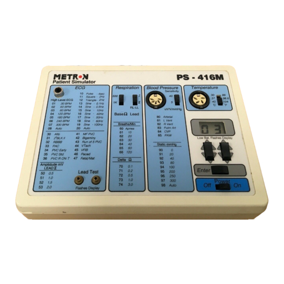
3. Operating PS-416M This chapter explains the PS-416M operating controls and terminals. 3.1 Control Switches and Termi- nals Front Panel Power Switch Turns the power on and off. LCD Display Keys Sets LCD display waveform values. Use the right key to enter units, and the left key to enter tens. -
Page 14: Use
Display and Keyboard The PS-416M has a two-digit display. To the left of the LCD display is a listing of available waveforms and two-digit codes. Access a waveform by displaying its corresponding two-digit code. Use the two keys below the LCD display to enter units and tens (the right key is for units;... - Page 15 400 or 700 series YSI probes. Temperature is selected by a slide switch. Prewired 400/700 YSI-series temperature cables to connect to the temperature connector are available from Metron AS (P.N. 17443). Unterminated cables are also available. CABLE CONNECTION MATRIX...
- Page 16 Battery Eliminator METRON’s AC Adapter plug-in power supply transformer allows you to use the PS-416M anywhere a standard electrical outlet is available. To attach the AC Adapter insert the adapter’s small connector into the micro jack labeled “Batt. Elim. 9V DC” on the right rear of the unit. Plug the large connector into the nearest standard electrical outlet.
-
Page 17: Control And Calibration
Press Enter and check that the display flashes once. 2. Measure the current consumption from the power supply. Requirement: 19mA 2mA. ± 3. Measure the operating voltage in PS-416M with the multimeter. The fol- lowing values are acceptable: Testpoints Value Maximum Deviation TP10 - TP4 ±... - Page 18 14. Set the power switch in position while momentarily holding down En- ter. The display will only show 0 in the right-hand column (the left col- umn will be blank). PS-416M is now in test/calibration mode. Connect a 10V 10mV voltage to J9 (the BP con- ±...
- Page 19 15. Measure and note the voltage between TP14 and TP16 (typ. <1mV). Set the display at 1 and press Enter. Measure the voltage once more and adjust P5 until the difference between the voltages is 120mV 200 V. ± 16. Repeat the previous instruction, only this time with the Sensitivity switch set to position 5.
- Page 20 This page intentionally left blank. 4-20...
-
Page 21: Component Functions And Parts
The unit is operated from a control panel, and generates simulated signals for testing ECGs and patient monitors. The signals are sent from the PS-416M via contacts situated on the front and top of the unit. The status of the signals is then displayed on an LCD panel. - Page 22 Ports E0 to E4 are connected to the switches on the control panel. These are read 50 times per second. If a switch changes its status from off to on, the program in the processor will execute the function that was linked to the operation.
-
Page 23: Component Parts
Output A7 on the processor is connected to the amplifier chain so that a short impulse here will simulate a pace-impulse at the ECG output. Re- sistors R36, R37, R38 and R39 set the level for the pace-impulse. 6. Respiration The other A/D channel in IC8 (Channel B) is used to generate the respi- ration signal. - Page 24 COMPONENT PART TYPE/VALUE DIAGRAM REFERENCE Op.ampl LT1013DN8 IC9, 1C10, 1Cl1, 1C16 Opto coupler 6N136HP IC12, 1C13, 1C14 DIA-converter DAC8043FP IC15, Opto coupler VTL5C7 IC17, 1C18 V-ref. LM-385Z IC19, Transistor BC547C Q1, Q20 Diode 1N4002 Diode 1N4148 D2, D3, D7, D8 Zenerdiode 17Vbip.
- Page 25 COMPONENT PART TYPE/VALUE DIAGRAM REFERENCE Resistor 5K6 1% 0.5W R37, R39 Resistor 11K 1% 0.5W R42, R45, R77, R78 Resistor 14K 1% 0.5W R5, R44, R26, R35 Resistor 15K8 0.50% 0.5W Resistor 17K8 0.50% 0.5W Resistor 0.5W Resistor 0.5W Resistor 23K7 0.50% 0.5W Resistor 0.5W...
- Page 26 COMPONENT PART TYPE/VALUE DIAGRAM REFERENCE IC-socket 8-pin DIL IC-socket 20 pin SIL 48-157-42 IC-socket 52 pin PLCC 48-109-41 Space bar Ritcho SRS4-4-0 Battery el.cont S-G9312#01 Female Test plug Male Test plug Female Phono-socket LPV1120-01(black) Female Header 2 pol 5046 Header 4-pol Header 6-pol...
-
Page 27: Appendix A: Diagrams
APPENDIX A: DIAGRAMS Component Location Diagram ......................Schematic Diagram Part 1 ........................Schematic Diagram Part 2 ........................5-27... - Page 28 This page intentionally left blank. 5-28...
-
Page 29: Component Location
Component Location 5-29... -
Page 30: Schematic Diagram Part 1
Schematic Diagram Part 1 5-30... -
Page 31: Schematic Diagram Part 2
Schematic Diagram Part 2 5-31... - Page 32 This page intentionally left blank. 5-32...
-
Page 33: Appendix B: Error Report Form, Ps-416M
APPENDIX B: ERROR REPORT FORM, PS-416M PS-416M PATIENT SIMULATOR ERROR REPORT FORM FRANCE NORWAY 1345 Monroe NW, Suite 255A 30, rue Paul Claudel Travbaneveien 1 Grand Rapids, MI 49505 91000 Evry, France N-7044 Trondheim, Norway Phone: (+1) 888 863-8766 Phone:... - Page 34 This page intentionally left blank. 5-34...
-
Page 35: Appendix C: Suggestion Form, Ps-416M
APPENDIX C: Suggestion Form, PS-416M PS-416M PATIENT SIMULATOR SUGGESTION FORM FRANCE NORWAY 1345 Monroe NW, Suite 255A 30, rue Paul Claudel Travbaneveien 1 Grand Rapids, MI 49505 91000 Evry, France N-7044 Trondheim, Norway Phone: (+1) 888 863-8766 Phone: (+33) 1 6078 8899... - Page 36 5-36...
Need help?
Do you have a question about the PS-416M and is the answer not in the manual?
Questions and answers