
Related Manuals for METRON QA-45


Summary of Contents for METRON QA-45
- Page 1 QA-45 User & Service Manual QA-45 Defibrillator and Transutaneous Pacemaker Analyzer P/N 13060...
- Page 2 METRON will, for a period of twelve (12) months from date of purchase, replace or repair any defective system, if the fault is due to a manufacturing defect. In no event will...
-
Page 3: Table Of Contents
2.4 Internal Paddles..........................4 2.5 Special Contacts..........................4 2.6 PRO-Soft QA-40M/45........................4 3. Operating QA-45..........................1 3.1 Control Switches and Connections.....................1 3.2 QA-45 Menu and Function Keys....................3 3.3 Menu and Messages: Defibrillator Mode..................4 3.4 Menu and Messages: Transcutaneous Pacemaker Mode............6 3.5 Test Result Printouts........................8 4. - Page 4 Manual Revision Record This record page is for recording revisions to your QA-45 User & Service Manual that have been published by METRON AS or its authorized representatives. We recommend that only the manage- ment or facility representative authorized to process changes and revisions to publications: •...
- Page 5 This page intentionally left blank.
-
Page 6: Introduction
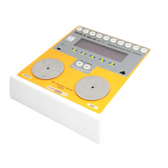
QA-45 has a built-in load resistance of 50 ohm, which roughly corresponds to the impedance of the human body. The de- fibrillator pads are placed on the QA-45 contact plates. Thus, the de- fibrillator is connected through the load resistance. When the defib- rillator is discharged, QA-45 calculates and displays the energy de- livered. -
Page 7: Defibrillator Analyzer Specifications
1.2 Defibrillator Analyzer Specifications 1. Energy Output Measurement High Range Voltage <5000 volts Maximum current 120 amperes Maximum energy 1000 Joules Accuracy ± 2 % of reading for >100 Joules ± 2 Joule of reading for <100 Joules Trigger level 100 volts Playback amplitude 1 mV/1000 V Lead I... - Page 8 2. ECG Wave ECG General Lead configuration 12-lead simulation. RL, RA, LA, LL, V1-6 Output impedance Limb leads 1000 ohms to RL V Leads 1000 ohms to RL All other signals are in relative proportion to Lead amplitude as follows: The amplitudes are shown for a Lead I amplitude by 1 mV: Lead I 1.0 mV (LA - RA)
- Page 9 blk II Second degree A-V block RBBB Right Bundle Branch Block Premature Atrial Contraction PVC_E Early PVC PVC_STD PVCRonT R on T PVC mfPVC Multifocal PVC bigeminy Bigeminy run5PVC Bigeminy Run of 5 PVCs vtach Ventricular Tachycardia Shock Advisory Test Algorithms ASYS Asystole SVTa_90...
-
Page 10: Transcutaneous Ppacemaker Analyzer Specifications
1.3 Transcutaneous PPace- maker Analyzer Specifications 1. TEST LOAD RANGE 50 to 2300 ohms in step of: 50 ohm up to 200 ohms 100 ohm from 200 up to 2300 ohms Accuracy 50 - 1300 ohm ±1% 1400 - 2300 ohm ±1.5 % Oscilloscope Output 50 - 150 ohm 10.24:1 amplitude attenuation... -
Page 11: General Information
(P/N 17021) Internal paddle-contact adapter (P/N 13403) Ground contact adapter (P/N 13404) Snap-to-banana adapters (10 pk) (P/N 17023) User and Service Manual QA-45 (P/N 13060) Additional Accessories Defib. paddle adapter (specify defibrillator type) (P/N 13410) Pacemaker external load cable (specify type pacemaker type}... - Page 12 Periodic Inspection The unit should be calibrated every 12 months.
-
Page 13: Installation
The customer should place a new purchase order to ensure delivery. 4. When returning an instrument to METRON AS, or the company representative, fill out the address label, describe what is wrong with the instrument, and provide the model and serial numbers. -
Page 14: Power
2. If PRO-Soft QA-40M/45 is being used, attach an RS-232 (null modem/data transfer configured) cable to the 9-pin D-sub outlet port located at the rear of the QA-45. Do not attach the printer cable to the QA-45. See below. However, if you are not using PRO-Soft QA-40M/45, and are sending directly to a printer for printouts, attach the printer cable to the 25-pin outlet port. - Page 15 main switch has to be switched off and then on again in order to use the instrument. 3. Changing Batteries. Open the compartments in the base of the NOTE instrument, replace the old batteries with new ones, and close Do not use mercury, air or car- the compartment covers.
-
Page 16: Internal Paddles
Certain defibrillators (automatic models and those with pacer op- tions) have special contacts that are fastened to the electrodes at- tached to the patient. Metron AS has special adapters to suit the ma- jority of these defibrillators. These are available as accessories. - Page 17 stored on disk, and the results of testing can be sent back to the equipment database to close a work order and update the service his- tory.
-
Page 18: Control Switches And Connections
3. Operating QA-45 This chapter explains the operating controls, switches and menus of the QA-45, details how to use them in testing , and provides general information on printouts and operator maintenance. 3.1 Control Switches and Connections Top Panel Power Switch Turns the power on and off. - Page 19 Low Level ECG 10 color-coded 4 mm safety terminals with snap-to-banana Connectors adapters. Pacer Input The pacer output cables are connected to these so that the Connectors pacer signal passes through the instrument with a variable load selectable from 50 to 2300 ohms.
-
Page 20: Menu And Function Keys
3.2 QA-45 Menu and Function Keys The QA-45 uses display and programmable function keys to provide flexibility and control over the operations. The upper part of the screen displays messages, status and results. The menu bar is at the bottom of the display. -
Page 21: Menu And Messages: Defibrillator Mode
3.3 Menu and Messages: Defibrillator Mode 1. Startup Screen. The following screen will be displayed for 2 seconds after the QA-45 has been switched on. 2. Main Menu Main Menu Bar (Page 1) - Mode switch in Low or High position. - Page 22 4. ADV. ALG. (Advisory Algorithms) (F2). These ECG algorithms are meant to test the analysis and prompt- ing feature of automatic and semi-automatic defibrillators. Choose desired selection by pressing UP (F2) or DOWN (F3). Save this under ‘Wave” in the STATUS field by pressing SELECT (F4).
-
Page 23: Menu And Messages: Transcutaneous Pacemaker Mode
3.4 Menu and Messages: Transcutaneous Pacemaker Mode 1. Startup Screen. The following screen will be displayed for 2 seconds after the QA-45 has been switched on. 2. Main Menu ain Menu Bar (Page 1) - Mode switch in PACE position. - Page 24 b. Second Menu Bar (Page 2) 3. SELECT LOAD (F1) Choose desired PACER load by pressing UP (F2) or DOWN (F3) and then SELECT (F4). Press CANCEL (F5) to cancel selection. 4. SELECT NOISE (F2) Choose desired noise for the immunity test by UP (F2) or DOWN (F3) and then SELECT (F4).
-
Page 25: Test Result Printouts
Se- lect PRINT HEADER (F4) if you want to print out a page with a new header. 2. Pace Mode. QA-45 prints out the test results, after the measure- ments, when you press PRINT RESULT (F4) in the Main menu. - Page 26 This page intentionally left blank.
-
Page 27: Defibrillator Mode Testing
QA-45 has a built-in load resistance of 50 ohm, which roughly corresponds to the impedance of the human body. The de- fibrillator pads are placed on the QA-45 contact plates. Thus, the de- fibrillator is connected through the load resistance. When the defib- rillator is discharged, QA-45 will calculate and display the energy delivered. -
Page 29: Energy Test
Use the LOW range for low energy testing, where the en- ergy does not exceed 50 Joule and the peak voltage does not exceed 1200 volts. 2. Securely place the defibrillator paddles on the QA-45 contact plates, and discharge the defibrillator. The APEX (+) pad Note... -
Page 30: Cardioversion Test
'v-fib'. 4.4 Cardioversion Test 1. Select ECG WAVE (F1) from the main menu. 2. The ECG Wave menu opens. QA-45 includes the following ECG wave selection for cardioversion tests, or for the testing of elec- trocardiograph moni tors. - Page 31 Save this under ‘Wave” in the STATUS field by pressing SE- LECT (F4). Press CANCEL (F5) to cancel selection. 3. QA-45 includes the following ECG wave amplitude options: 0.5 mV, 1.0 mV, 1.5 mV and 2.0 mV. To change wave ampli- tude select more-2 on the main menu.
-
Page 32: Maximum Energy Charging Time Test
4. Set the defibrillator to synchronized cardioversion mode. Dis- charge the defibrillator over the instrument's load resistance. 5. QA-45 measures the time delay in milliseconds (ms) between the top of the 'R' wave and the discharging of the defibrillator pulse. This delay will be shown in the LCD display as: 'Delay: xxx ms'. -
Page 33: Shock Advisory Algorithm Test
When the defibrillator is charged, discharge it through the instru- ment. 5. Charging time will be shown in the display as ‘Chrg T: xx.x MS’ under RESULT. 4.6 Shock Advisory Algorithm Test 1. This tests the analysis and prompting of automatic and semi-au- tomatic defibrillators. - Page 34 Press CANCEL (F5) to cancel selection. The ECG signal is output through the low-level ECG connectors, high-level ECG connector, and paddle contact plates on the QA-45. 4. Set the defibrillator to analyze the ECG rhythm and operate in the automatic and semi-automatic mode.
-
Page 35: Transcutaneous Pacemaker Mode Testing
1. Connect the pacer output cables to the pacer input connectors. 2. Switch the mode switch to ‘PACE’ mode. 3. Turn the QA-45 on. The following will be displayed in the LCD display for about two seconds: 4. The following main menu will then appear: 5. - Page 36 Select the desired noise form by pressing UP (F2) or DOWN (F3) and then Select (F4). Press CANCEL (F5) to cancel the selection. After selection the main menu will reappear.
-
Page 37: Demand Sensitivity Test
If it is not sensed, a message 'exceeded' is displayed which means that the pacemaker needs an amplitude more than 100 mV for sensing at that setting. If the wave is sensed, QA-45 then reduces the amplitude in steps until it reaches the lowest value required for the pacemaker to sense it. -
Page 39: Refractory Period Test
1. General. This test is used to test the time interval in millisec- onds (ms) during which the pacemaker is insensitive to any ex- ternal inputs. QA-45 does this by measuring the maximum time interval after the generation of a pacer pulse, and maximum time interval after a QRS wave. - Page 40 QRS wave is ignored. The sensed refractory period is measured in a similar man- ner, except that QA-45 now generates two square waves in- stead of one. The first square wave is generated at a fixed time delay from a pacer pulse, which is greater than the paced refractory period.
- Page 41 Upon completion of testing the results will be displayed un- der RESULT. Press REF. PER. CANCEL (F5) to cancel the test.
- Page 42 This page intentionally left blank.
-
Page 43: Control And Calibration
Set the switches on QA-45 to the following positions: Mode: Power: Connect a power supply to the battery eliminator input on QA-45. Adjust the power supply to 9V (±0.2v) with a power limitation of 200 mA (±50 mA). 6.3 References The function keys are numbered 1 to 5, with switch 1 farthest to left. - Page 44 Measure the operating voltage with the multimeter. Requirement: 6.9V (±0.3v). Return the operating voltage to 9.0V. and reset QA-45 by switching off the power for a short period. 7. Select 80 BPM in the ECG Wave Menu. Connect the oscillo- scope to TP1 for signal, and TP8 to ground.
- Page 45 Adjust two measurement values by pressing + and -. The values will be stored in QA-45's EEPROM when SAVE & QUIT is pressed. 15. Set the power switch to Off. Remove the covers at J106 and J107.
- Page 46 5 Joules (±20 %), and that the measured volt- age is approx. 500V. 25. Connect a PC to the serial port and try to control QA-45 re- motely. Check that communication functions in both directions. 26. Go to the System Test Menu and choose ECG +. (Last setting for pacer should be default setting: 500 ohm).
- Page 47 27. Connect a 10V (±0.01v) power source to the pacer input. (Last setting for pacer should be default setting: 500 ohm). Measure the voltages on pacer module with the multimeter. The follow- ing values are acceptable: Test point Level Maximum Deviation TP1 - TP2 +61.04 mV...
- Page 48 30. Set the pacer load to 500 ohm. Connect a pulse generator to the pacer input. The following values are acceptable: Parameter Value Max. Deviation Rate: 80 ppm ±0.5 ppm Width: 10 ms ±0.3 ms Amplitude: 20 mA ±1 mA Energy: 2.0 mJ ±0.5 mJ...
-
Page 49: Component Functions And Parts
7. Component Functions and Parts This chapter provides a detailed description of the functions of the main components of the QA-45, as well as a parts list for cross-ref- erence. The QA-45 is based on 4 circuit boards: a processor board, sensor board, ECG signal distribution board and pacer module. - Page 50 +5V voltage falls below 4.75V. D6 and C13 provide the printer output with its own +5V. D6 will block power inflow through the printer cable when the QA-45 is switched off. D7 and D8 rectify an AC signal from pin 2 IC-5, and build up a voltage of -18V via C29.
-
Page 51: Sensor Board
SPI lines. 2. Switches For Operation (Schematic Diagram 4). The front panel on the QA-45 has 5 push buttons and 2 sliding controls for operation. The push buttons SW101 - SW105 are soft keys to which different functions are assigned by the soft- ware. -
Page 52: Ecg Signal Distribu- Tion Board
IC107 regulates the -9 volt potential down to stable -5V for use in the A/D converter system. Dl14 prevents incorrect polariza- tion and latch-up when the QA-45 is switched on and off. D108, D109 and Dl10 provide over-voltage protection. 6. Measurement Input (Schematic Diagram 6). -
Page 53: Pacer Unit
500 ohm for all outputs. Filters on the outputs ensure damp- ing of high-frequency components in the signal. 7.5 Pacer Unit (Refer to QA-45 ECG Pacer Unit Component Location Diagram and Schematic Diagram 8) The pacer module consists of 3 blocks. These are the resistor group, stimulus output and input amplifier. -
Page 54: Component Parts
7.6 Component Parts COMPONENT PART TYPE/VALUE QTY. DIAGRAM REFERENCE PROCESSOR BOARD Processor board AR-095 Microprocessor MC68HC11G5FN IC13 LH5160HD-10L IC16 EPROM 27C010-120 IC14 EEPROM X24C16P PAL. 22V10Z-25PC IC15 D/A converter MX7528KN Op.amp LM358P IC17 Op.amp LT1013DN8 IC2, IC3 V-ref. LM-385Z-2V5 IC12, IC18 Timer LMC555CN IC106... - Page 55 COMPONENT PART TYPE/VALUE QTY. DIAGRAM REFERENCE EMI Filter DSS306-91Y F1-F18, F21, F22, F25 - F31 EMI Filter DSS710-D22 EMI Filter DSS306-91F F20, F23, F24, F32 - F34, F37 - F38 Battery contact FemaleS-G9312#0 Header 2 pole J6, J10 Phono-base CLIFF PHS2A D-sub 9p Male 90 degrees D-sub...
- Page 56 COMPONENT PART TYPE/VALUE QTY. DIAGRAM REFERENCE Potentiometer 10K 20 turn P103, P104 Resistor pack 8 x 10K RP101 Cer. capacitor 220pF 50V C102 Cer. capacitor 470pF 50V C101 Multilay. X7R 10nF Cl13 Multilay. X7R 100nF 50V C104-Cl12, Cl16, C120 Multilay. X7R 470nF 50V C114 Electrolyte Capacitor...
- Page 57 COMPONENT PART TYPE/VALUE QTY. DIAGRAM REFERENCE Resistor 1K52 0.1% 0.5W R21, R22 Resistor 1K8 1% 0.5W Resistor 2K 0.1% 0.5W Resistor 10K 0.1% 0.5W R9, R13, R,?.5, R28 Resistor 10K 1% 0.5W R15, R24, R27 Resistor 20K 0.1% 0.5W R8, R10, R14, R16 Resistor 24K 0.1% 0.5W R17, R18...
- Page 58 This page intentionally left blank.
-
Page 59: Appendix A - Diagrams
Appendix A - Diagrams Processor Board Component Location Diagram................A-2 Schematic Diagram Part 1 (Processor Board)................A-3 Schematic Diagram Part 2 (Processor Board)................A-4 Schematic Diagram Part 3 (Processor Board)................A-5 Sensor Board Component Location Diagram................A-6 Schematic Diagram Part 4 (Sensor Board)..................A-7 Schematic Diagram Part 5 (Sensor Board)..................A-8 Schematic Diagram Part 6 (Sensor Board)..................A-9 ECG Signal Distribution Board Component Location Diagram..........A-10 Schematic Diagram Part 7 (ECG Signal Distribution Board).............A-11... - Page 68 A-10...
- Page 69 A-11...
- Page 70 A-12...
- Page 71 A-13...
- Page 72 Product: Version: Serial no.: Description of the situation prior to the error: Description of the error: (METRON AS internally) Comments: Received date: Correction date: Ref No. Critical Normal Minor FRANCE...
- Page 73 (name) Address: Fax: E-mail: Date: Improvement Suggestion Product: Version: Description of the suggested improvement: (METRON AS internally) Comments: Received date: Correction date: Ref No. Critical Normal Minor...
- Page 74 Grand Rapids, MI 49505 91000 Evry, France N-7044 Trondheim, Norway Phone: (+1) 888 863-8766 Phone: (+33) 1 6078 8899 Phone: (+47) 7382 8500 Fax: (+1) 616 454-3350 Fax: (+33) 1 6078 6839 Fax: (+47) 7391 7009 E-mail: support.us@metron-biomed.com E-mail: info@metron.fr E-mail: support@metron.no...
Need help?
Do you have a question about the QA-45 and is the answer not in the manual?
Questions and answers