Advertisement
Quick Links
Advertisement

Subscribe to Our Youtube Channel
Related Manuals for AUTODIAGGER AD100+


Summary of Contents for AUTODIAGGER AD100+
- Page 1 Autodiagger AD100+ User Manual...
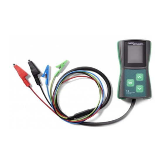
- Page 2 Introduction The Autodiagger AD100+ is a handheld tester that is used to test and diagnose alternator charging problems by replicating the digital signals from a vehicle’s ECU. The AD100+ tester can test an alternator while it is still installed on a vehicle or on a testbench.
-
Page 3: Device Operation
Device Operation The device powers on automatically after connecting power to the B+ and B- leads. The test subject selection menu will then appear. The desired parameter is selected by pressing the and buttons and confirmed by a short press on the OK button to enter the testing mode. After pressing OK, the display will present the following information: 1. - Page 4 COM, LIN, BSS Testing COM, LIN, BSS Testing Mercedes, Opel, Audi, BMW, Renault, VW, Ford COM DFM COM/LIN COM/LIN2 LIN2 Alternator Connection: COM pin RC (Green) DFM pin M (Blue) B+ connector B+ (Red) Alternator bracket/casing B- (Black)
- Page 5 COM, LIN, BSS Testing Select the COM function from the main menu and confirm by pressing the OK button: The device will go into the COM testing mode and display the following information: Selected function Required voltage Actual voltage DFM value Additional information During the test, after starting the alternator drive, the actual voltage value should correspond to the required value and the DFM value should correspond to the current alternator load.
- Page 6 LIN 24V Testing LIN 24V Testing GRC Mercedes W LIN 15 S DFM Alternator connection: W pin Existing tachometer connection. LIN pin RC (Green) 15 pin (IG) Existing 15 / ignition connection. S pin (Battery Sense) Existing S / battery sense connection. DFM pin Leave disconnected.
- Page 7 LIN 24V Testing Select the LIN24 function from the main menu and confirm by pressing the OK button. The device will go into the LIN24 testing mode and display the following information: Selected function Required voltage Actual voltage DFM value Additional information During the test, after starting the alternator drive, the actual voltage value should correspond to the required value and the DFM value should correspond to the current alternator load.
- Page 8 Ford SIG Testing Ford SIG Testing Ford, Mazda, Volvo Alternator connection: FR pin M (Blue) SIG pin RC (Green) S pin Existing S / battery sense connection B+ connection B+ (Red) Alternator bracket/casing B- (Black) The connection of the S pin is connected independently of the AD100+, by using the connectors located in the vehicle or on the testbench.
- Page 9 Ford SIG Testing During the test, after starting the alternator drive, the actual voltage value should correspond to the required value and the DFM value should correspond to the current alternator load. Some discrepancies between the voltage values are acceptable. What is important is the appropriate reaction of the alternator –...
- Page 10 Mazda P-D Testing Mazda P-D Testing Mazda Alternator connection: D pin RC (Green) P pin M (Blue) B+ connection B+ (Red) Alternator bracket/casing B- (Black)
- Page 11 Mazda P-D Testing After connecting the testing device, the main menu will appear on the display: Select the P-D function and confirm by pressing the OK button. Selected function Required voltage Actual voltage DFM value During the test, after starting the alternator drive, the actual voltage value should correspond to the required value.
- Page 12 General Motors L-RVC Testing General Motors L-RVC Testing General Motors, Opel, Vauxhall F(RVC) L(PCM) Alternator connection: L(PCM) pin RC (Green) F(RVC) pin M (Blue) B+ connection B+ (Red) Alternator bracket/casing B- (Black)
- Page 13 General Motors L-RVC Testing After connecting the testing device, the main menu will appear on the display: Select the L-RVC function and confirm by pressing the OK button. The device will go into the L-RVC testing mode and display the following information: Selected function Required voltage Actual voltage...
- Page 14 Toyota RLO Testing Toyota RLO Testing Toyota Alternator connection: IG pin Existing IG connection. RLO pin RC (Green) L pin Existing L (Control Lamp) connection. M pin (DFM) M (Blue) B+ connection B+ (Red) Alternator bracket/casing B- (Black) The connection of the L and IG pins are implemented independently of the AD100+, by using the connectors located in the vehicle or on the testbench.
- Page 15 Toyota RLO Testing After connecting the testing device, the main menu will appear on the display: Select the RLO function and confirm by pressing the OK button. The device will go into the RLO testing mode and display the following information: Selected function Required voltage Actual voltage...
- Page 16 i-STARS Testing i-STARS Testing B+ D D LIN GND i-STARS connections: Plug: B+ connection Existing alternator battery positive. LIN pin RC (Green) GND pin Existing alternator ground. Power cables: B+ connection B+ (Red) Alternator bracket/casing B- (Black) M (Blue) is left disconnected when testing. The connection of the B+ and GND pins are implemented independently of the AD100+, by using the connectors located in the vehicle or on the testbench.
- Page 17 i-STARS Testing Select the COM function from the main menu and confirm by pressing the OK button. The device will go into the COM testing mode and display the following information: Selected function Required voltage Actual voltage DFM value Additional information During the test, after starting the alternator drive, the actual voltage value should correspond to the required value and the DFM value should correspond to the current alternator load.
-
Page 18: Frequently Asked Questions
Frequently Asked Questions Can the device be damaged due to improper connection? The device is resistant to connection errors from typical applications and voltage ranges. Can the device damage connected units? The device cannot directly damage any connected units, however the range of voltage sent to the alternator is very broad and includes prohibited values (over 15V), which can result in electrical system errors if the alternator is tested without removing it from the vehicle. - Page 19 Frequently Asked Questions Why does an alternator with a COM interface start working only after I change the required voltage for the first time? This is due to the alternator voltage regulator function. This type of behaviour is standard and confirms the alternator is working properly.
-
Page 20: Software Update
Software Update The AD100+ is equipped with NFC (Near Field Communication) that enables wireless software updates. Updates are safe and the device always holds both the new and last version of the software for easy rollback. Device Serial Number Every AD100+ device has a unique serial number. This number is required to get update information and to purchase new software updates. -
Page 21: Software Update Procedure
Software Update Software Update Procedure Power up AD100+. While in main menu press UP arrow and while holding press OK button, keep buttons pressed until the update menu appears on screen. [1] Release buttons. Acknowledge update by pressing OK button. [2] On phone please enable flight mode, after that please enable WiFi and NFC. - Page 22 Software Update Place phone on the AD100+ (AD100+ NFC antenna is located at the bottom, the phone NFC antenna is usually located under the battery). The application will automatically start to update the software when NFC antennas are aligned. [5] 10.
- Page 23 Test Plugs EC5725 EC5758 EC5755 Ford Alternator Plug Denso Alternator Plug Denso / Mitsubishi Plug 3 Pin with 300mm lead 4 Pin with 150mm lead 3 Pin Oval with 150mm lead EC5756 EC5760 EC5803 Hitachi / Mitsubishi Alternator Plug Denso Alternator Plug Denso Alternator Plug 2 Pin with lead 3 Pin with 150mm lead...
- Page 24 Test Plugs EC5782 EC5784 EC5786 Bosch / Valeo Alternator Plug Bosch / Valeo Alternator Plug Bosch / Valeo Alternator Plug 2 Pin with 2 leads 2 Pin with 300mm lead 2 Pin with 300mm lead EC5791 EC5764 EC5754 Delco Alternator Plug Bosch / Valeo Alternator Plug Bosch / Valeo Alternator Plug 4 Pin with 4 x 200mm leads...
- Page 25 Alternator Plug Set EC5827: 20pc Alternator Plug Set The EC5827 is a 20 piece alternator plug set which is an ideal addition for alternator test benches or regulator testers. Please note the kit does not include the 5-pin Bosch/Mitsubishi plug (EC5759) as standard.
Need help?
Do you have a question about the AD100+ and is the answer not in the manual?
Questions and answers