Table of Contents
Advertisement
Quick Links
Advertisement
Table of Contents

Related Manuals for GIGA-BYTE TECHNOLOGY GA-H97M-HD3


Summary of Contents for GIGA-BYTE TECHNOLOGY GA-H97M-HD3
- Page 1 GA-H97M-HD3 User's Manual Rev. 1001 12ME-H97MHD3-1001R...
- Page 2 Mar. 20, 2014 Mar. 20, 2014 Copyright © 2014 GIGA-BYTE TECHNOLOGY CO., LTD. All rights reserved. The trademarks mentioned in this manual are legally registered to their respective owners. Disclaimer Information in this manual is protected by copyright laws and is the property of GIGABYTE.
-
Page 3: Table Of Contents
Table of Contents GA-H97M-HD3 Motherboard Layout ................4 GA-H97M-HD3 Motherboard Block Diagram ..............5 Chapter 1 Hardware Installation ..................6 Installation Precautions ................... 6 ..................7 Installing the CPU .................... 9 Installing the Memory ..................10 Installing an Expansion Card ................. 10 Back Panel Connectors ................. 10 Internal Connectors .................. -
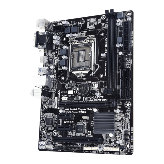
Page 4: Ga-H97M-Hd3 Motherboard Layout
GA-H97M-HD3 Motherboard Layout KB_MS_USB ATX_12V_2X4 LGA1150 HDMI R_USB30 SATA3 GA-H97M-HD3 USB30_LAN AUDIO CPU_FAN SYS_FAN Realtek ® GbE LAN PCIEX16 ® PCIEX1_1 Super I/O Intel ® PCIe to PCI Bridge B_BIOS PCIEX1_2 CODEC M_BIOS CLR_CMOS F_AUDIO F_USB2 F_USB1 F_PANEL Box Contents... -
Page 5: Ga-H97M-Hd3 Motherboard Block Diagram
GA-H97M-HD3 Motherboard Block Diagram 1 PCI Express x16 LGA1150 PCIe CLK Dual Channel Memory HDMI DVI-D PCI Express Bus Dual BIOS D-Sub 6 SATA 6Gb/s PCI Express Bus Intel ® 6 USB 2.0/1.1 PCIe CLK Realtek ® GbE LAN 6 USB 3.0/2.0... -
Page 6: Chapter 1 Hardware Installation
Chapter 1 Hardware Installation Installation Precautions The motherboard contains numerous delicate electronic circuits and components which can become manual and follow these procedures: Prior to installation, make sure the chassis is suitable for the motherboard. warranty sticker provided by your dealer. These stickers are required for warranty validation. Always remove the AC power by unplugging the power cord from the power outlet before installing or removing the motherboard or other hardware components. - Page 7 Support for Intel Core i7 processors/Intel Core i5 processors/ ® ™ ® ™ Intel Core i3 processors/Intel Pentium processors/Intel Celeron processors ® ™ ® ® ® ® in the LGA1150 package L3 cache varies with CPU Chipset Intel H97 Express Chipset ®...
- Page 8 Internal 1 x 24-pin ATX main power connector 1 x 8-pin ATX 12V power connector Connectors 6 x SATA 6Gb/s connectors 1 x CPU fan header 1 x system fan header 1 x front panel header 1 x front panel audio header 1 x USB 3.0/2.0 header 2 x USB 2.0/1.1 headers 1 x serial port header...
-
Page 9: Installing The Cpu
Unique Features Support for Q-Flash Support for Smart Switch Support for Xpress Install Bundled Norton ® Software Intel Rapid Start Technology ® Intel Smart Connect Technology ® Intel Smart Response Technology ® Intel Small Business Advantage ® Operating Support for Windows 8.1/8/7 System Form Factor Micro ATX Form Factor;... -
Page 10: Installing The Memory
Installing the Memory Read the following guidelines before you begin to install the memory: Make sure that the motherboard supports the memory. It is recommended that memory of the same capacity, brand, speed, and chips be used. Always turn off the computer and unplug the power cord from the power outlet before installing the memory to prevent hardware damage. - Page 11 DVI-D Port (Note) DVI-D connection to this port. HDMI Port The HDMI port is HDCP compliant and supports Dolby True HD and DTS HD audio output. You can use this port to connect your HDMI-supported monitor. The maximum supported dependent on the monitor being used. After installing the HDMI device, make sure to set the default sound playback device to HDMI.
-
Page 12: Internal Connectors
Internal Connectors ATX_12V_2X4 F_USB30 F_USB1/F_USB2 CPU_FAN SYS_FAN SATA3 0/1/2/3/4/5 F_PANEL Read the following guidelines before connecting external devices: First make sure your devices are compliant with the connectors you wish to connect. Before installing the devices, be sure to turn off the devices and your computer. Unplug the power cord from the power outlet to prevent damage to the devices. - Page 13 1/2) ATX_12V_2X4/ATX (2x4 12V Power Connector and 2x12 Main Power Connector) With the use of the power connector, the power supply can supply enough stable power to all the components off and all devices are properly installed. The power connector possesses a foolproof design. Connect the power supply cable to the power connector in the correct orientation.
- Page 14 5) SATA3 0/1/2/3/4/5 (SATA 6Gb/s Connectors) The SATA connectors conform to SATA 6Gb/s standard and are compatible with SATA 3Gb/s and SATA 1.5Gb/s standard. Each SATA connector supports a single SATA device. The Intel Chipset supports RAID ® Pin No. Pin No.
- Page 15 your chassis front panel audio module to this header. Make sure the wire assignments of the module connector match the pin assignments of the motherboard header. Incorrect connection between the module connector and the motherboard header will make the device unable to work or even damage it. For HD Front Panel Audio: For AC'97 Front Panel Audio: Pin No.
- Page 16 The COM header can provide one serial port via an optional COM port cable. For purchasing the optional COM port cable, please contact the local dealer. Pin No. Pin No. NDCD- NDSR- NSIN NRTS- NSOUT NCTS- NDTR- NRI- No Pin 11) LPT (Parallel Port Header) The LPT header can provide one parallel port via an optional LPT port cable.
-
Page 17: Chapter 2 Bios Setup
the CMOS values, use a metal object like a screwdriver to touch the two pins for a few seconds. Open: Normal Short: Clear CMOS Values Always turn off your computer and unplug the power cord from the power outlet before clearing the CMOS values. -
Page 18: Startup Screen
Startup Screen The following startup Logo screen will appear when the computer boots. Function Keys There are two different BIOS modes as follows and you can use the <F2> key to switch between these modes. setups more quickly and easily. Classic Setup is the conventional BIOS Setup interface where you can press the arrow keys on your keyboard to move among the items and press <Enter>... - Page 19 M.I.T. Current Status This screen provides information on CPU/memory frequencies/parameters. Advanced Frequency Settings Processor Graphics Clock CPU Upgrade (Note) CPU Clock Ratio Allows you to alter the clock ratio for the installed CPU. The adjustable range is dependent on the CPU being installed.
- Page 20 No. of CPU Cores Enabled (Note 1) Allows you to select the number of CPU cores to enable in an Intel ® Auto Hyper-Threading Technology (Note 1) Allows you to determine whether to enable multi-threading technology when using an Intel CPU that ®...
- Page 21 Advanced Memory Settings (Note) The settings above are synchronous to those under the same items on the Advanced Frequency Settings menu. Memory Boot Mode Provides memory detection and training methods. boot. Disable Fast Boot Detect and train memory at every single boot. Memory Enhancement Settings Memory Timing Mode Manual and Advanced Manual allows the Channel Interleaving, Rank Interleaving, and memory timing...
- Page 22 PC Health Status Enabled Clears the record of previous chassis intrusion status and the Displays the detection status of the chassis intrusion detection device attached to the motherboard CI header "Yes", otherwise it will show "No". To clear the chassis intrusion status record, set to Enabled, save the settings to the CMOS, and then restart your system.
-
Page 23: System Information
Miscellaneous Settings Allows you to set the operation mode of the PCI Express slots to Gen 1, Gen 2, or Gen 3. Actual operation Auto DMI Gen2 Speed Disabled Sets the DMI link speed to Gen 1. 3DMark01 Boost System Information This section provides information on your motherboard model and BIOS version. -
Page 24: Bios Features
Hard Drive BBS Priorities submenu will be presented here. string. Or if you want to install an operating system that supports GPT partitioning such as Windows 7 64-bit, select and devices that support Boot from LAN function, etc. Press <Enter> on this item to enter the submenu that presents the devices of the same type that are connected. - Page 25 Fast Boot Enables or disables Fast Boot to shorten the OS boot process. Ultra Fast provides the fastest bootup VGA Support Allows you to select which type of operating system to boot. Auto Enables legacy option ROM only. Fast Boot is set to Enabled or Ultra Fast. USB Support Disabled All USB devices are disabled before the OS boot process completes.
- Page 26 Dynamic Storage Accelerator Enables or disables Intel Dynamic Storage Accelerator. When enabled, the hard drive I/O performance ® VT-d (Note) Enables or disables Intel ® Windows 8 Features CSM Support Never Disables UEFI CSM and supports UEFI BIOS boot process only. Windows 8 Features is set to Windows 8.
-
Page 27: Peripherals
Administrator Password BIOS Setup. Differing from the user password, the administrator password allows you to make changes to all BIOS settings. User Password Setup. However, the user password only allows you to make changes to certain BIOS settings but not all. To cancel the password, press <Enter>... - Page 28 Auto BIOS routes the sharable ports to EHCI controller. Then it uses ACPI protocols to provide an option to enable the xHCI controller and reroute the sharable ports. Note: This is the recommended mode when BIOS does NOT have xHCI pre-boot support. Enabled All shared ports are eventually routed to the xHCI controller during the BIOS boot process.
- Page 29 Integrated SATA Controller SATA Mode Selection to AHCI mode. RAID Enables RAID for the SATA controller. Serial ATA Port 0/1/2/3/4/5 Port 0/1/2/3/4/5 Hot plug External SATA parallel port. Serial Port A Parallel Port Device Mode Parallel Port is set to Enabled. Selects an operating mode for the Intel(R) Smart Connect Technology ISCT Support Enables or disables Intel...
-
Page 30: Power Management
Power Management Power Loading Enables or disables dummy load. When the power supply is at low load, a self-protection will activate causing it to shutdown or fail. If this occurs, please set to Enabled. Auto Resume by Alarm If enabled, set the date and time as following: Wake up hour/minute/second: Set the time at which the system will be powered on automatically. - Page 31 Allows the system to be turned on by a PS/2 keyboard wake-up event. Note: To use this function, you need an ATX power supply providing at least 1A on the +5VSB lead. Password Set a password with 1~5 characters to turn on the system. Keyboard 98 Press POWER button on the Windows 98 keyboard to turn on the system.
-
Page 32: Save & Exit
Save & Exit Save & Exit Setup Press <Enter> on this item and select Yes. This saves the changes to the CMOS and exits the BIOS Setup program. Select No or press <Esc> to return to the BIOS Setup Main Menu. Exit Without Saving Press <Enter>... -
Page 33: Chapter 3 Appendix
Chapter 3 Appendix Before you begin Windows setup disk. Motherboard driver disk. A USB thumb drive A. Installing SATA hard drive(s) in your computer Attach one end of the SATA signal cable to the rear of the SATA hard drive and the other end to available SATA port on the motherboard. - Page 34 Enter the Intel ® Step: 1. After the POST memory test begins and before the operating system boot begins, look for a message which 2. After you press <Ctrl> + <I>, the MAIN MENU screen will appear. If you want to create a RAID array, select Create RAID Volume in MAIN MENU and press <Enter>.
-
Page 35: Drivers Installation
Drivers Installation After installing the operating system, insert the motherboard driver disk into your optical drive. Click install. You can click the Xpress Install the arrow icon to individually install the drivers you need. For more software information, please visit GIGABYTE's website. - 35 -... -
Page 36: Regulatory Statements
Regulatory Statements Regulatory Notices This document must not be copied without our written permission, and the contents there of must not be imparted Contravention will be prosecuted. We believe that the information contained herein was accurate in all respects at the time of printing. GIGABYTE cannot, however, assume any responsibility for errors or omissions in this text. Also note that the information in this document is subject to change without notice and should not be construed as a commitment by GIGABYTE. - Page 37 This equipment has been tested and found to comply with the limits for a Class B digital device, pursuant to Part 15 of the FCC Rules. These limits are designed to provide reasonable protection against harmful interference in a residential installation. This equipment generates, uses, and can radiate radio frequency energy and, if not installed and used in accordance with the instructions, may cause harmful interference to radio communications.
- Page 38 - 38 -...
- Page 39 - 39 -...
-
Page 40: Contact Us
Contact Us Address: No.6, Bao Chiang Road, Hsin-Tien Dist., New Taipei City 231,Taiwan TEL: +886-2-8912-4000, FAX: +886-2-8912-4005 You may go to the GIGABYTE website, select your language in the language list on the top right corner of the website. GIGABYTE Global Service System question, please link to: http://ggts.gigabyte.com.tw Then select your language to enter the system.
Need help?
Do you have a question about the GA-H97M-HD3 and is the answer not in the manual?
Questions and answers