
Subscribe to Our Youtube Channel
Related Manuals for GIGA-BYTE TECHNOLOGY GA-Z97-HD3


Summary of Contents for GIGA-BYTE TECHNOLOGY GA-Z97-HD3
- Page 1 GA-Z97-HD3 GA-H97-HD3 User's Manual Rev. 1001 12ME-Z97HD3-1001R GA-Z97-HD3 GA-H97-HD3...
- Page 2 Apr. 10, 2014 Apr. 10, 2014 Copyright © 2014 GIGA-BYTE TECHNOLOGY CO., LTD. All rights reserved. The trademarks mentioned in this manual are legally registered to their respective owners. Disclaimer Information in this manual is protected by copyright laws and is the property of GIGABYTE.
-
Page 3: Table Of Contents
Table of Contents GA-Z97-HD3/GA-H97-HD3 Motherboard Layout ............4 GA-Z97-HD3/GA-H97-HD3 Motherboard Block Diagram ..........5 Chapter 1 Hardware Installation ..................6 Installation Precautions ..................6 ..................7 Installing the CPU .................... 9 Installing the Memory ..................10 Installing an Expansion Card ................. 10 Back Panel Connectors .................. 10 Internal Connectors .................. -
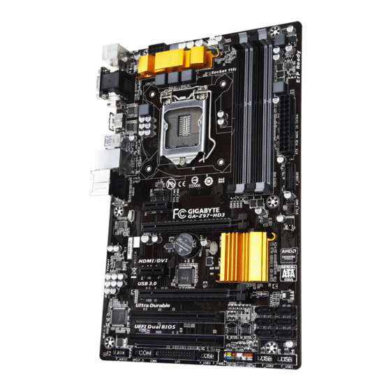
Page 4: Ga-Z97-Hd3/Ga-H97-Hd3 Motherboard Layout
F_USB2 SPDIF_O F_PANEL F_USB1 Box Contents GA-Z97-HD3 or GA-H97-HD3 motherboard Motherboard driver disk Two SATA cables User's Manual I/O Shield The box contents above are for reference only and the actual items shall depend on the product package you obtain. -
Page 5: Ga-Z97-Hd3/Ga-H97-Hd3 Motherboard Block Diagram
GA-Z97-HD3/GA-H97-HD3 Motherboard Block Diagram 1 PCI Express x16 DVI-D LGA1150 PCIe CLK HDMI Dual Channel Memory DMI 2.0 PCI Express Bus D-Sub RJ45 Dual BIOS Realtek ® GbE LAN 6 SATA 6Gb/s PCI Express Bus Intel ® 6 USB 3.0/2.0 Intel ®... -
Page 6: Chapter 1 Hardware Installation
Chapter 1 Hardware Installation Installation Precautions The motherboard contains numerous delicate electronic circuits and components which can become manual and follow these procedures: Prior to installation, make sure the chassis is suitable for the motherboard. warranty sticker provided by your dealer. These stickers are required for warranty validation. Always remove the AC power by unplugging the power cord from the power outlet before installing or removing the motherboard or other hardware components. - Page 7 * When installing a x8 or above card in the PCIEX4 slot, make sure to set PCIE Slot 2 x PCI Express x1 slots 2 x PCI slots Multi-Graphics Support for 2-Way AMD CrossFire ™ technology Technology Only for GA-Z97-HD3. Only for GA-H97-HD3. - 7 -...
- Page 8 Storage Interface Chipset: 6 x SATA 6Gb/s connectors Support for RAID 0, RAID 1, RAID 5, and RAID 10 Chipset: Internal 1 x 24-pin ATX main power connector 1 x 8-pin ATX 12V power connector Connectors 6 x SATA 6Gb/s connectors 1 x CPU fan header 3 x system fan headers 1 x front panel header...
-
Page 9: Installing The Cpu
Unique Features Fast Boot ON/OFF Charge Smart TimeLock Smart Recovery 2 System Information Viewer USB Blocker Support for Q-Flash Support for Smart Switch Support for Xpress Install ® Bundled Norton ® Intel Rapid Start Technology Software ® Intel Smart Connect Technology ®... -
Page 10: Installing The Memory
Installing the Memory Read the following guidelines before you begin to install the memory: Make sure that the motherboard supports the memory. It is recommended that memory of the same capacity, brand, speed, and chips be used. Always turn off the computer and unplug the power cord from the power outlet before installing the memory to prevent hardware damage. - Page 11 DVI-D Port (Note) connection to this port. HDMI Port The HDMI port is HDCP compliant and supports Dolby True HD and DTS HD output. You can use this port to connect your HDMI-supported monitor. The maximum supported resolution , but the actual resolutions supported are dependent on the monitor being used.
-
Page 12: Internal Connectors
Internal Connectors ATX_12V_2X4 F_USB30 F_USB1/F_USB2/F_USB3 CPU_FAN SYS_FAN1/2/3 SATA3 0/1/2/3/4/5 F_PANEL Read the following guidelines before connecting external devices: First make sure your devices are compliant with the connectors you wish to connect. Before installing the devices, be sure to turn off the devices and your computer. Unplug the power cord from the power outlet to prevent damage to the devices. - Page 13 1/2) ATX_12V_2X4/ATX (2x4 12V Power Connector and 2x12 Main Power Connector) With the use of the power connector, the power supply can supply enough stable power to all the components off and all devices are properly installed. The power connector possesses a foolproof design. Connect the power supply cable to the power connector in the correct orientation.
- Page 14 5) SATA3 0/1/2/3/4/5 (SATA 6Gb/s Connectors) The SATA connectors conform to SATA 6Gb/s standard and are compatible with SATA 3Gb/s and SATA 1.5Gb/s standard. Each SATA connector supports a single SATA device. The Intel ® Chipset supports RAID 0, RAID 1, a RAID array.
- Page 15 The front panel audio header supports Intel ® your chassis front panel audio module to this header. Make sure the wire assignments of the module connector match the pin assignments of the motherboard header. Incorrect connection between the module connector and the motherboard header will make the device unable to work or even damage it. For HD Front Panel Audio: For AC'97 Front Panel Audio: Pin No.
- Page 16 sound cards. For example, some graphics cards may require you to use a S/PDIF digital audio cable for digital audio output from your motherboard to your graphics card if you wish to connect an HDMI display to the graphics card and have digital audio output from the HDMI display at the same time. For information about connecting the S/PDIF digital audio cable, carefully read the manual for your expansion card.
-
Page 17: Chapter 2 Bios Setup
the CMOS values, use a metal object like a screwdriver to touch the two pins for a few seconds. Open: Normal Short: Clear CMOS Values Always turn off your computer and unplug the power cord from the power outlet before clearing the CMOS values. 14) BAT (Battery) in the CMOS when the computer is turned off. -
Page 18: Startup Screen
Startup Screen The following startup Logo screen will appear when the computer boots. Function Keys There are three different BIOS modes as follows and you can use the <F2> key to switch between these modes. The provides a fancy and user-friendly BIOS environment where users can easily point and click through various settings and make adjustments for optimum performance. - Page 19 Uncore Ratio Allows you to set the CPU Uncore ratio. The adjustable range is dependent on the CPU being used. Uncore Frequency Displays the current CPU Uncore frequency. Only for GA-Z97-HD3. Intel ® CPUs' unique features, please visit Intel's website.
- Page 20 Intel(R) Turbo Boost Technology (Note) Allows you to determine whether to enable the Intel CPU Turbo Boost technology. Auto lets the BIOS Turbo Ratio (1-Core Active~4-Core Active) (Note) Allows you to set the CPU Turbo ratios for different number of active cores. Auto sets the CPU Turbo ratios Turbo Power Limit (Watts) Allows you to set a power limit for CPU Turbo mode.
- Page 21 Advanced Voltage Settings This sub-menu allows you to set CPU, chipset and memory voltages. PC Health Status Enabled Clears the record of previous chassis intrusion status and the will show "No" at next boot. Only for GA-Z97-HD3. - 21 -...
- Page 22 Displays the detection status of the chassis intrusion detection device attached to the motherboard CI clear the chassis intrusion status record, set to Enabled, save the settings to the CMOS, and then restart your system. CPU Vcore/CPU VRIN/Dram Voltage/+3.3V/+5V/+12V/CPU VAXG Displays the current system voltages.
-
Page 23: System Information
Miscellaneous Settings Allows you to set the operation mode of the PCI Express slots to Gen 1, Gen 2, or Gen 3. Actual operation support up to Gen 2 mode only. Auto DMI Gen2 Speed Disabled Sets the DMI link speed to Gen 1. 3DMark01 Boost System Information This section provides information on your motherboard model and BIOS version. -
Page 24: Bios Features
Or if you want to install an operating system that supports GPT partitioning such as Windows 7 64-bit, select Bootup NumLock State Administrator Password/User Password item. Setup A password is only required for entering the BIOS Setup program. System A password is required for booting the system and for entering the BIOS Setup program. Allows you to determine whether to display the GIGABYTE Logo at system startup. - Page 25 Partial Initial Part of the USB devices are disabled before the OS boot process completes. Fast Boot is set to Enabled. This item is disabled when Fast Boot is set to Ultra Fast. PS2 Devices Support Disabled All PS/2 devices are disabled before the OS boot process completes. Enabled All PS/2 devices are functional in the operating system and during the POST.
- Page 26 Boot Mode Selection Allows you to select which type of operating system to boot. UEFI and Legacy Allows booting from operating systems that support legacy option ROM or UEFI Legacy Only Allows booting from operating systems that only support legacy Option ROM. UEFI Only Allows booting from operating systems that only support UEFI Option ROM.
-
Page 27: Peripherals
Peripherals card or the onboard graphics. XHCI Mode Allows you to determine the operating mode for the xHCI controller in OS. Smart Auto This mode is available only when the BIOS supports the xHCI controller in the pre-boot environment. This mode is similar to Auto, but it adds the capability to route the ports pre-boot environment. - Page 28 Intel Processor Graphics Intel Processor Graphics Memory Allocation Intel(R) Rapid Start Technology Enables or disables Intel ® Legacy USB Support XHCI Hand-off Determines whether to enable XHCI Hand-off feature for an operating system without XHCI Hand-off EHCI Hand-off Determines whether to enable EHCI Hand-off feature for an operating system without EHCI Hand-off USB Storage Devices Displays a list of connected USB mass storage devices.
-
Page 29: Power Management
Hot plug External SATA parallel port. Serial Port A Parallel Port Device Mode Parallel Port is set to Enabled. Selects an operating mode for the Intel(R) Smart Connect Technology ISCT Support Enables or disables Intel ® Realtek PCIe GBE Family Controller Power Management Power Loading Enables or disables dummy load. - Page 30 Resume by Alarm If enabled, set the date and time as following: Wake up hour/minute/second: Set the time at which the system will be powered on automatically. Note: When using this function, avoid inadequate shutdown from the operating system or removal of the AC power, or the settings may not be effective.
-
Page 31: Save & Exit
PCIe ASPM Auto lets the Platform Power Management is set to Enabled CPU DMI Link ASPM Control Auto lets the BIOS automatically Platform Power Management is set to Enabled. PCH DMI Link ASPM Control Auto lets the BIOS Platform Power Management is set to Enabled Save &... - Page 32 If your system becomes unstable and you have loaded the BIOS default settings, you can use this function Select File in HDD/USB/FDD automatically created by the BIOS, such as reverting the BIOS settings to the last settings that worked Before you begin Windows setup disk.
- Page 33 5. After setting the capacity, move to Create Volume and press <Enter> to begin. 6. After completing, you'll be brought back to the Intel(R) Rapid Storage Technology screen. Under RAID Volumes you can see the new RAID volume. To see more detailed information, press <Enter> on the volume Enter the Intel ®...
-
Page 34: Drivers Installation
Drivers Installation After installing the operating system, insert the motherboard driver disk into your optical drive. Click on the message "Tap to choose what happens with this disc" on the top-right corner of the screen and select "Run Run. "Xpress Install" will automatically scan your system and then list all of the drivers that are recommended to install. -
Page 35: Regulatory Statements
Regulatory Statements Regulatory Notices This document must not be copied without our written permission, and the contents there of must not be imparted Contravention will be prosecuted. We believe that the information contained herein was accurate in all respects at the time of printing. GIGABYTE cannot, however, assume any responsibility for errors or omissions in this text. Also note that the information in this document is subject to change without notice and should not be construed as a commitment by GIGABYTE. - Page 36 This equipment has been tested and found to comply with the limits for a Class B digital device, pursuant to Part 15 of the FCC Rules. These limits are designed to provide reasonable protection against harmful interference in a residential installation. This equipment generates, uses, and can radiate radio frequency energy and, if not installed and used in accordance with the instructions, may cause harmful interference to radio communications.
- Page 37 - 37 -...
- Page 38 - 38 -...
- Page 39 - 39 -...
-
Page 40: Contact Us
Contact Us Address: No.6, Bao Chiang Road, Hsin-Tien Dist., New Taipei City 231,Taiwan TEL: +886-2-8912-4000, FAX: +886-2-8912-4003 You may go to the GIGABYTE website, select your language in the language list on the top right corner of the website. GIGABYTE Global Service System question, please link to: http://ggts.gigabyte.com.tw Then select your language to enter the system.
Need help?
Do you have a question about the GA-Z97-HD3 and is the answer not in the manual?
Questions and answers