Table of Contents

Related Manuals for EM TEST CWS 500A / 75


Summary of Contents for EM TEST CWS 500A / 75
- Page 1 ELECTROMAGNETIC COMPATIBILITY CONSULTING AND SIMULATION Continuous Wave Simulator Type CWS 500A / 75 IEC 61000-4-6 / EN 61000-4-6 MANUAL Version : 2.10 / 26.10.00 Replaces : 2.01 / 25.05.00 Filename : CWSA-A5.DOC Printdate : 22.08.01...
-
Page 2: Table Of Contents
Generator function check............29 6.3. Calibration ................30 6.3.1. General ..................30 6.3.2. Calibration setup EM TEST and IEC 61000-4-6 ...... 31 6.3.3. Calibration set-up with CDN............. 32 6.3.4. Calibration Menu ..............33 6.3.5. Calibration set-up with EM Clamp..........35 6.3.6. - Page 3 7.2. Control unit................38 7.3. Generator unit ................38 7.4. High frequency power unit ............38 7.5. 6dB attenuator................38 7.6. CDN Coupling/decoupling network .......... 39 7.7. Test set-up ................40 7.8. Test level and modulation ............41 Technical Data................42 Maintenance ................
-
Page 4: Safety
Safety 1.1. Safety aspects Observe all of these precautions to ensure your personal safety. The generators correspond to Installation Category II (overvoltage category). Read the following operation manual carefully. Pay special attention to both safety and operation details!!! Symbols marked on equipment WARNING Risk of electric shock. -
Page 5: Prior To Turning On The Equipment
Read the following operation manual carefully !!! 1.2. Prior to Turning on the Equipment - Before putting the instrument into operation, please check the equipment you have received for damage due to transportation. Check the single boxes as well as the generator itself. In case of mechanical damage, please contact the manufacturer before switching the unit on. -
Page 6: Maintenance, Adjustments, Exchange Of Parts
- The user is not allowed to independently change or modify any EM TEST generator. For service and repair only original EM TEST parts and components shall be used. -
Page 7: Testing And Danger
1.4. Testing and danger All tests offered by the High Voltage or EMC generators are immunity tests on electronic equipment or devices. These tests are potentially dangerous for the operator. Therefore it is the responsibility of the user to avoid critical failures and risks to the environment and operator. -
Page 8: Measures
1.4.1. Measures: 1. EMC and High Voltage test areas must always be supplied by a decoupled and well known power mains supply. 2. The decoupling can be realized either by - filtering - or isolating transformer 3. In case of using an isolating transformer the test area again can be protected by ground fault relays. -
Page 9: Danger From The Eut
1.4.3. Danger from the EUT device under test become dangerous due to the influence applied test pulses or test energy. Therefore the operator shall take care to the following aspects: As soon as the EUT ceases to operate as intended the test shall be stopped immediately. -
Page 10: Setup The Cws 500A
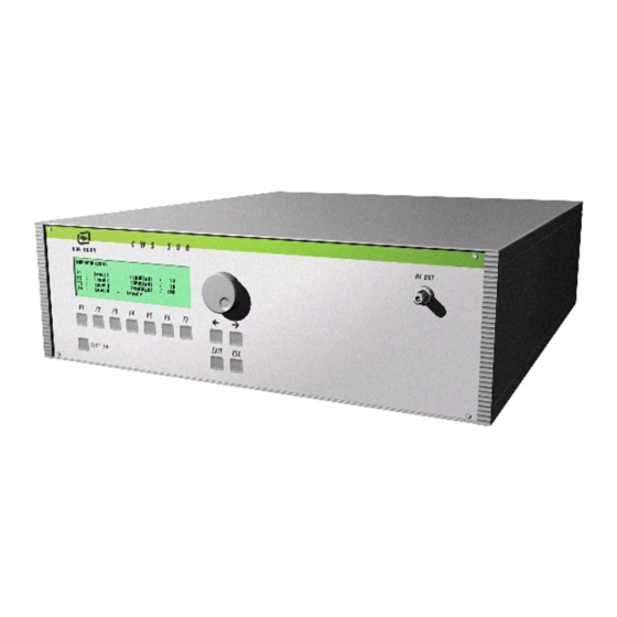
2. Setup the CWS 500A 2.1. Connections CWS 500 Below are all possible connections to the CWS 500A. The RF signal output is on the BNC plug on this side. Fig 1 : CWS 500 connection front side Fig 2 :All other connectors are on the rear. -
Page 11: Test Setup Cws 500
2.2. Test setup CWS 500 Test Setup with CDN Test Setup with CNC 508... -
Page 12: Part Names And Functions
2.3. Part names and Functions Continuous-Wave-Simulator CWS 500A Switching Matrix CNC 508 1:8 Switching Matrix for CDN, EM clamp, and other devices Attenuator 6 dB 6dB / 40 W 6dB / 75W Coupling decoupling Network Types: CDN-M 1; M 2; M 3; M4; M 5; CDN-S1-50/75Ω;... - Page 13 Calibration CWS-Cal Basic calibration kit Transport case 150Ω to 50Ω Adapter BNC cable 0.5m Cal adapter according to CDN Adapter R100 150Ω to 50Ω Adapter R100A 150Ω to 50Ω Adapter for current clamp cal fixture...
-
Page 14: Frequently Asked Questions
Frequently Asked Questions No items under this chapter. See in other chapter if you have a questions. For other information ask contact the local sales representative or send a email to EM TEST AG info@emtest.com sales @emtest.ch... -
Page 15: Operating Functions
Operating Functions 4.1. Front view CW S 5 0 0 EM TEST RF Out <− −> EXIT ESC TEST ON Display Exit ”Test On" Escape Function keys "F1..F7" RF output LED RF output monitor Cursor keys "←" and "→" Knob (Inc / Dec) Display All functions and parameters are displayed (8 lines with max. -
Page 16: Rear View
At this output the RF power is available. The 6dB-attenuator is connected via coax cable. For conducting tests together with CDN’s, EM clamps or current injection clamps, the generator must always be loaded with a 6dB-attenuator (see chapter 5.5 Test Set-up). Output: 0-30V e.m.f. - Page 17 A complete restart of the routine is necessary. The message "FAIL 1" is indicated in the LCD-Display as well as in the ICD software. Fail detection FAIL 2 The BNC input FAIL 2 can be used for failure detection on the EUT. If the input is set to ground (chassis), the failure will be detected and the test continues normally.
-
Page 18: Operation
EXIT will reset the firmware to the main screen. All functions are indicated on the display; max. 8 lines and 40 characters. Start-up display EM TEST Warm Up C W S 5 0 0 ← Generator Model ← Frequency range RF 9kHz –... - Page 19 Page 1 (Main menu) MAIN MENU F1 : Quick Start F2 : User test routines F3 : Standard test routines F7 : Service F1 Quick Start Easy and fast operation of the equipment without special functions (memory). F2 User test routines The user can save and recall his own specific test routines.
-
Page 20: Quick Start
5.2. Quick Start Easy and very fast operation of all standard functions of the equipment. Page 2 (Show parameters) Page 3 (Change) QUICK START QUICK START 10,0V Mod = 1kHz 5.0MHz Voltage V : 1.0 V - 30.0V Frequency f :0.009 MHz - 250.0MHz START CHANGE CAL PRINT... -
Page 21: User Test Routines
5.3. User test routines The user can change, save and recall his own specific test routines. All special functions and routines are stored in this part of the user menu. Page 2 (Selection of the function) Page 3 (Select store) USER TEST ROUTINES VOLTAGE - SWEEP F1 : Voltage-Sweep... -
Page 22: Voltage Sweep
5.3.1. Voltage sweep The test level is changed from V1 to V2. After the dwell time td and the pause time tr, the test level is changed by ∆V until the set value for V2 is reached. It is not necessary that V1 is smaller than V2. After selecting one of the stored test files, the test parameters will be shown in the display. -
Page 23: Frequency Sweep
5.3.2. Frequency sweep The test frequency is changed from f1 to f2. After the dwell time td and the pause time tr, the test frequency is changed by ∆f until the set value for f2 is reached. The step size ∆f can be either a fixed frequency value or a percentage of the preceding frequency value. -
Page 24: Dwell Time Sweep
5.3.3. Dwell time sweep The dwell time is changed from td1 to td2. After the dwell time td and the pause time tr, the dwell time is changed by ∆td until the set value for td2 is reached. After selecting one of the stored test files the test parameters will be shown in the display. -
Page 25: Standard Test Routines Acc. To Iec 61000-4-6
5.4. Standard test routines acc. to IEC 61000-4-6 The display shows a list of different test levels. The CWS 500A offers pre- programmed values of the actual standards IEC 61000-4-6 / EN 61000-4-6. Page 2 (Standard test levels) Page 3 (Show values) STANDARD TEST Standard test routine Level 3... -
Page 26: Service
F3 : Setup F4 : Change Standard Parameters F1 Addresses The addresses of EM TEST AG Switzerland and EM Test GmbH Germany will be displayed. A list of the world-wide sales partners is part of the annex of this manual. -
Page 27: Set-Up
5.6. Set-up This menu helps the user to define the configuration of the CWS 500A. Page 3 (Setup overview) Setup F1 : Change language F2 : LCD Backlighting F3 : Interfaces F4 : Keyboard Beeper F5 : Timer F1 Change language The user can choose between two languages, German and English. -
Page 28: Putting Into Operation
Putting into Operation 6.1. Security aspects Tests with conducted RF-disturbances, induced by radio-frequency fields, are immunity tests on electronic equipment. Therefore it is the responsibility of the user to avoid critical failures and risks to the environment and the operators. Long and distributed lines of the EUT are able to radiate a certain energy to their vicinity. - Page 29 CDN’s before opening the housing. 6. Only trained and experienced people are allowed to perform service and repair to the instruments. Please contact an EM TEST service center or your local sales partner for repairing or servicing the units.
-
Page 30: Generator Function Check
6.2. Generator function check As with all measuring and test equipment, the continuous wave simulator type CWS 500A should be checked for function and accuracy from time to time. The check should be conducted as listed below. - Connect the RF-output of the CWS 500A to the 6dB-attenuator with a coaxial cable. -
Page 31: Calibration
6.3. Calibration 6.3.1. General A high frequency voltmeter is included within the CWS 500A. This measuring device is used for calibration purposes. The complete test set- up, including CDN’s and cables, can be calibrated via this voltmeter. The internal controller can compensate the frequency behavior of the test set-up according to the requirements of IEC 61000-4-6. -
Page 32: Calibration Setup Em Test And Iec 61000-4-6
Calibration setup EM TEST and IEC 61000-4-6 The setup for calibration acc. IEC 61000-4-6 is shown in the figure below. EM Test has carefully tested the calibration setup and propose to eliminate the 150Ω terminating resistor on the AE port for CDN calibration. -
Page 33: Calibration Set-Up With Cdn
For calibration acc. the standard it is necessary to order the additional calibration adapter for the AE port. 6.3.3. Calibration set-up with CDN max. Voltage on the CAL INPUT U = 3V CAL INPUT (50Ω) 150Ω to 50Ω Adaptor 30mm CWS50 100 Ω... -
Page 34: Calibration Menu
F1...F4 is used, for the CDN calibration data, by the factory setting Additionally the user gets the Cal data on the ICD disk in the directory A:\CDN available in the quality system of EM TEST. A new CAL routine will overwrite the selected store F1 .. F4. Therefore the operator has to confirm that he really wants to overwrite the existing data. - Page 35 This includes event protocols and Cal data. Another license code enables the implementation of external measuring devices when they are controllable via IEEE488 (GPIB)-interfaces. For more information please consult EM TEST or any of our local sales representatives.
-
Page 36: Calibration Set-Up With Em Clamp
6.3.5. Calibration set-up with EM Clamp The calibration with an EM Clamp is similar to the CDN calibration. Take care by connecting the EM clamp in the calibration setup. The EUT port must be on the measuring device side. Otherwise the calibration in the higher frequency range is wrong. -
Page 37: Fail Input
6.4. Fail Input Fail 1: A short-circuit at the Fail 1 input will stop the running test procedure. It is not possible to continue the same test. Up to 10 test stops can be recorded. Each new stop will overwrite the previous memory. -
Page 38: Test Equipment Cws 500A
Test Equipment CWS 500A 7.1. Construction The CWS 500A continuous wave simulator is divided into three main parts. The control unit is completely separated and decoupled from the RF power part. Rear panel I I I Frontside Control unit Transformer Power supply filter Power supply Connection board... -
Page 39: Control Unit
7.2. Control unit The control part includes the processing unit and the driver electronics for the high frequency part. All signals coming from and going to the processing part are decoupled. 7.3. Generator unit The signal generator provides all RF signals required for the operation of the amplifier. -
Page 40: Cdn Coupling/Decoupling Network
7.6. CDN Coupling/decoupling network The CDN’s are connected externally at the output of the 6dB-attenuator. The coupling network is used to couple the interference to the lines of the equipment under test. The coupling is realized with capacitors or resistors having a sufficient bandwidth according to IEC 61000-4-6. -
Page 41: Test Set-Up
7.7. Test set-up The following information is important for a correct test set-up: 50Ω CWS500 100mm 30mm ground reference insulation plane 1. All lines not being tested must be decoupled: - by CDN’s where the RF input ports are terminated by a 50Ω load resistor - by an EM Clamp - by ferrites on the cables 2. -
Page 42: Test Level And Modulation
7.8. Test level and modulation Test level according IEC 61000-4-6 Testing is normally carried out at discrete frequencies in the range 150 kHz to 80 MHz. Frequency range 150 kHz to 180MHz Level Voltage level (e.m.f) in [dBµV] special special Frequency sweep When using discrete frequency sweep, then the step size shall not exceed 1% of the start and thereafter 1% of the preceding frequency value. -
Page 43: Technical Data
Technical Data Test Level: Output Level 1 - 30Ve.m.f. after 6dB-attenuator Output power 75W (nominal) Output impedance 50 Ohm max. VSWR 1:1.2 at all phase angles and at max. power (without destruction) Harmonic distortion < 15dBc (at max. power) Test frequencies Sinusoidal (CW) 9kHz - 250MHz Frequency bands... - Page 44 Timing: Dwell time td = 0,3s - 9999.9s Rest time tr = 0 / 0,3s - 9999.9s For pulse modulation td = 3s - 9999.9s Output Direct Option Coupling matrix (1 to 8 RF-outputs) EUT control BNC input FAIL 1 Fail 1;...
- Page 45 General data Dimensions 19"/3HE Weight approx. 9kg Power supply 110-230V/ max 50/60Hz Input power max. 380W Power factor cosφ=0,98 at max output power acc. to IEC 555 Fuse 2x6,3AT (115V) // 2x3,15AT (230V) Cooling active cooling, air ventilation Environment conditions 10°C - 40°C Humitity Max.
-
Page 46: Maintenance
Maintenance 9.1. General The generator is absolutely maintenance-free by using solid state semiconductors. The generator uses forced air cooling. Take care not to cover the cooling slots. Delivery Groups 10.1. Basic equipment Continuous wave simulator type CWS 500A Mains cable Manual CWS 500A Calibration certificate ISMICD software ( without option printer and instrument ) -
Page 47: Remote Control
Remote Control 11.1. Interfaces All following interfaces are standard features of the CWS 500A. Serial RS 232 interface with 1’200 - 19’200 Baud (8-databit, 1 start/stop bit) 25- Pin SubD Signal Signal 9- Pin SubD PC / Printer CWS 500A ---- ---- ----... -
Page 48: General Information
11.2. General information The remote commands must be closed by a <LF>. Just before the <LF> the check sum of the complete string must be transmitted. Calculating : check sum = 100 - (sum of all ASCII codes in one byte) NU,180;]<LF>... -
Page 49: Parameter Of The Remote Commands
11.3. Parameter of the remote commands Name Descript. Min - Max. Step Unit Parameter 0.2 – 1.0 10 - 600 Voltage 1.2 - 4.0 4.5 - 7.0 8.0 - 20.0 22.0 - 60.0 Frequency 0.009 - 250.000 0.001 9-250000 0.3 - 9999,9 3 - 99999 Dwell-Time 0 = OFF... -
Page 50: C Commands
11.4. C commands Comm. Syntax Description Checks the connection of the interface. The CWS 500A will go to remote mode in RS232. The CWS feedback is: CWS500A,CN,SWN,SERVICE,Version; CN using a matrix 0 -> no external matrix 1 -> 1 to 8 Matrix SWN is the software number of the equipment. -
Page 51: N Commands
11.5. N commands Comm. Syntax Description NU,U; The NU command sends a new voltage level. NF,f; The NF command sends a new frequency value. NA,Mod; The NA command sends a new level for modulation. ND,td; The ND command sends a new level for dwell-time. NK,U,f;... -
Page 52: A Commands
11.7. A commands Comm. Syntax Description The AA command starts the test routine. At first all parameters and the routine must be handled by a C-command. The AS command stops a running test. The AR command stops a running test and returns the CWS 500A to local mode. -
Page 53: Icd Software
ICD Software 12.1. Introduction ISMICD is the freeware tool that is delivered along with every CWS500A simulator. The ICD are used to upload and download calibration data to the CWS 500A and to run a test routine. A manual for ICD is provided only for purchased ICD complete versions with the printer or instrument option. -
Page 54: Installed Files On Your Hard Drive
12.3. Installed Files on your Hard Drive The install path is Progdir = C:\EMTEST\ICD32 <DIR> Directory for Calibration data RESULT <DIR> Directory for Result data TEST <DIR> Directory for Test data ICD32 PMM6600 DEMO32 HP5347 DIA32 HP5347A2 MCF DLOG32 KEITHL01 MCF COMP32 NRVD_1 OWL52F... -
Page 55: Appendix
Appendix 13.1. Schematic Blockdiagram CWS 500... -
Page 56: Declaration Ce- Conformity
The declaration of conformity, together with the measuring/test reports, the measuring/test conditions and the failure criterions are available at the EMC laboratory of EM TEST AG in Switzerland as well as at the EMC laboratory of EM TEST GmbH in Germany. - Page 57 CE Conformity The generators must conform with the EMC directive of the EU. This means that the generic standards EN 50081.1/2 and/or EN 50082-1/2 must be applied. At the moment is no product standard is applicable. 1.1 Immunity according 50082-2 An assignment to the generic standard for industry is realistic, because - the test equipment is used in an environment with heavy interferences.
-
Page 58: Declaration Of Safety Requirements
13.3. Declaration of safety requirements Declaration of Conformity EM TEST AG Sternenhofstrasse 15 CH 4153 Reinach Switzerland Declare under our sole responsibility the product: Continuous wave generator Type CWS 500A To which this declaration relates in conformity with the following standard... -
Page 59: List Of Sales Representatives
Fax +43 (0)1545 146439 email: adms-cta@zip.com.au email: sales@uei-vienna.com Belgium China COMTEST INSTRUMENTATION B.V. EM TEST Representative Office Beijing Industrieweg 12 Friendship Hotel, Room 20337 NL-2382 NV ZOETERWOUDE 3 Baishiqiao Road Tel. +31 (0)71 5417 531 BEIJING 100873, P. R. CHINA Fax +31 (0)71 5415 926 Tel. - Page 60 Israel Italy ERANTEL ELECTRONICS LTD VOLTA S.p.A. 10, Yad-Haruzim St. Via del Vigneto 23 IL-KFAR-SABA, 44106 I-39100 BOLZANO Tel. +972 (0)9 767 13 32 Tel. +39 0471 561 000 Fax +972 (0)9 765 56 07 Fax +39 0471 561 100 email: eran@silram.co.il email: info@volta.it http:// www.volta.it...
-
Page 61: Application
Application 14.1. Introduction As electronic devices and systems grow increasingly more complex, they become more and more suspectible to interference. This owes largely to lower signal levels being used, which increases the ratio of unwanted signals to wanted signal. When electronic circuits are subjected to interferences, their performance may be degraded causing malfunction and even catastrophic failure. -
Page 62: Coupling Network
14.2. Coupling network - Due to the various national safety instructions, the coupling network has no on/off key as well as no internal fuse protection. The EUT must be fused by the user. - Due to the technical specification in the standard, higher ground currents may be expected. -
Page 63: Test Sequence As Per En 50082-2
14.4. Test sequence as per EN 50082-2 Select the standard routine Level X - Level Y of the internal CWS 500 test routines. The generator will then automatically use the required test sequence. The operator is free to program the individual levels according to the upper limits in the standard routines. -
Page 64: Test Setup With Bci
14.6. Test Setup with BCI When using a clamp injection and common mode impedance requirements cannot be met at the AE side, it is necessary that the common mode impedance of the AE is less than or equal to the common mode impedance of the EUT port being tested. -
Page 65: Definitions
14.7. Definitions - Electromagnetic Compatibility (EMC) Ability of a device to function correctly in its electromagnetic environment without introducing intolerable disturbances to this environment or to any other equipment. - Coupling Interaction between circuits, transferring energy from one circuit to another. -
Page 66: Sources Of Interferences
14.8. Sources of interferences Sources result from the redistribution of electromagnetic energy. Such redistributions and their most important sources are listed below. - Stationary and non-stationary transmitters Both stationary high power radio transmitters and non-stationary walkie- talkies operating in the immediate vicinity of systems or equipment, lead to uncontrolled electromagnetic irradiation... - Page 67 - Atmospheric discharges, lightning, and switching transients Lightning and switching transients appearing in low voltage networks of industrial installations are the origin of pulse-cancelling interference. Parameters: range of voltage some tens of kV, range of current some tens of kA, high-energy pulses with rise times in the microsecond range.
Need help?
Do you have a question about the CWS 500A / 75 and is the answer not in the manual?
Questions and answers