Table of Contents
Advertisement
Quick Links
The benchmark for emc
Instruction
Manual
esd NX30
esd NX30.1
ESD Simulator
Electrostatic discharges either from a human body to any other
part or between two different objects can cause persistent dis-
turbances or even destruction to sensitive electronics or con-
trols. esd NX30 is an ESD tester to simulate ESD pulses at
higher voltages up to 30 kV in both air and contact discharge
mode. It therefore satisfiers requirements exceeding the
EN/IEC 61000-4-2 test levels and complies to automotive test
applications
.
Version:
Replaces:
Filename:
Print date:
1.00.8 / 4.18.2019
1.00.7 / 4.12.2019
UserManual-esdNX30-E-V1.00.8.doc
18.04.19
•
IEC 61000-4-2
•
EN 61000-4-2
•
ISO 10605
Advertisement
Table of Contents

Subscribe to Our Youtube Channel
Related Manuals for EM TEST esd NX30


Summary of Contents for EM TEST esd NX30
-
Page 1: Esd Simulator
ISO 10605 trols. esd NX30 is an ESD tester to simulate ESD pulses at higher voltages up to 30 kV in both air and contact discharge mode. It therefore satisfiers requirements exceeding the... -
Page 2: Table Of Contents
Battery charger / power supply unit ......................11 4.2.2 Options ..............................11 4.2.3 R/C Discharge Networks........................... 11 4.2.4 Remote triggering (esd NX30 only) ......................12 4.2.5 Interlock (esd NX30 only) ......................... 13 COMMISSIONING ........................15 Function test ............................. 15 OPERATION .......................... 16 Switching on .............................. - Page 3 Exchanging the R/C network ........................29 9.2.1 Reduction of the pulse repetition rate through higher capacitance ............29 Repairs ..............................29 esd NX30 system error messages ......................30 Disposal ..............................30 TECHNICAL SPECIFICATIONS .................... 32 CE-certificate of compliance ........................33 Low Voltage Directive 2014/35/EU ....................
-
Page 4: Explanation Of The Symbols Used In This Manual
NX30 EM Test EXPLANATION OF THE SYMBOLS USED IN THIS MANUAL Please take note of the following explanations of the symbols used in order to achieve the optimum benefit from this manual and to ensure safety during operation of the equipment. -
Page 5: Safety
WARNING The esd NX30 simulator is not a toy! It is a professional tool and belongs only in the hands of specialists and appropriately trained personnel. When powered by its own batteries the generator can be active even without any power cable being connected. -
Page 6: Introduction
Such tests provide valuable information about the immunity of the system to effects that occur only sporadically under operating conditions and hence represent difficult to detect sources of disruption. The ESD simulator esd NX30 fulfils the requirements of numerous applications in an ideal manner, thus: Ergonomic shape: For non-tiring use. -
Page 7: Effects On The Eut
ESD (electrostatic discharge) testing usually shows up all the weak spots in the HF-range of a piece of equipment simulta- neously. The uses to which the esd NX30 ESD simulator can be put hence go way beyond those called for in standard- conform applications. -
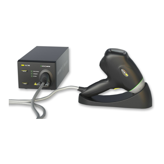
Page 8: The Esd Nx30 System
The esd NX30 offers optimal freedom of movement around the work-place and is an ideal test instrument not just for the development engineer but also for quality control purposes, system tests and for investigations in the field. -
Page 9: Function Modules
NX30 EM Test 4.1.1 Function modules The base station contains the battery supply, the high voltage generator and regulator as well as several safety features. The pistol houses the interchangeable pulse network, high voltage relay, the exchangeable discharge tip, measuring elec- tronics and the touch sensitive input / display panel. -
Page 10: Operating Elements
The esd NX30 is switched on and off with the main power switch. The significance of the elements in the display field can be seen in the following picture. Further information can be found in section "Operation". -
Page 11: Battery Charger / Power Supply Unit
Battery life expectancy (esd NX30 only): • The esd NX30 is designed to provide 30,000 discharges at the full 30 kV over many hours • Ambient temperatures over 50°C can lead to degradation of the battery. If treated carefully, more than 300 charge / discharge cycles can be expected without a noticeable reduction in capacity. -
Page 12: Remote Triggering (Esd Nx30 Only)
Remote triggering (esd NX30 only) This port is indented to allow the user to connect external signals in order to remote control the esd NX30 generator, as well as to connect external accessories like the charge removing device. See tables and graphs below for detailed signal descrip- tion and drive circuitry information. -
Page 13: Interlock (Esd Nx30 Only)
2. Internal emergency off button opens the interlock. Outputs 1. Operating mode: the esd NX30 can generate no high voltage as long as the interlock is not closed. High voltage genera- tion is prevented if the interlock is opened during a test procedure. - Page 14 NX30 EM Test S: External safety switch (e.g. test enclosure hood, door contact, panic button, etc...) Several interlock inputs of this type may be connected in series. The contacts should be connected in series if numerous access barriers are necessary. Either one open contact or a voltage of more than 1.5 V at the input is sufficient to disable the simulator.
-
Page 15: Commissioning
Plug the interlock terminators into the base station, if equipped • Connect the earth cable correctly (the esd NX30 must never be switched on without a solid earth connection being made). • Allow the instrument to dry out if any condensation has occurred Function test Switch the simulator on with the POWER switch. -
Page 16: Operation
EM Test OPERATION This section of the manual provides a guide through the numerous operating possibilities of the esd NX30. The operation, hierarchically arranged, is therefore easy to remember. The display shows unmistakable information about the parameters that have been set and the operating status of the simulator. -
Page 17: Display Mode
NX30 EM Test 6.3.1 Display mode When adjusting some parameters, a keyboard and up / down buttons can be selected. Numerical values (voltage, preset counter, random repetition times) can be entered just the same as with a pocket calcula- tor. -
Page 18: Counter
NX30 EM Test 6.3.4 Counter Use the counter button to branch into the corresponding menu. Choose the counter mode: Preset counter on / off. In the On state the counter content can be set. When the simulator is in operation the preset counter counts down until it reaches 0, which then terminates the selected test sequence. -
Page 19: Repetition
NX30 EM Test 6.3.5 Repetition The repetition button takes you into the menu to select either single pulses or a repetition rate from 0.5 to 25 Hz in air dis- charge, or from 0.5 to 20 Hz in contact discharge mode. - Page 20 EM Test EUT discharge on esd NX30/NX30.1: To remove the charged energy of a EUT, the simulator has an switch. With the time of the charge removing procedure can be programmed. All timing parameters can be set from 0.1 up to 99 s in 0.1 s steps.
-
Page 21: Settings
The Log is in volatile RAM and will be saved each time the gun is switched off or goes to sleep. Please switch off the gun properly, simply cutting the power to the esd NX30 can result in loss of data. - Page 22 NX30 EM Test Only users of esd.control can set the Last Cal and certificate number. For best results, be sure to use an au- thorized AMETEK CTS calibration laboratory. NOTE Instruction Manual V 1.00.7 22 / 33...
-
Page 23: Threshold
If somehow the maximum voltage could not be reached or hold, the esd NX30 comes out with an error message Nr. 210 cal. Failed. The calibration procedure is diagnosing, to which voltage level the instrument works properly. This voltage value will be shown on screen. -
Page 24: Continuous Operation
NX30 EM Test 6.3.16 Continuous operation Continuous operation can be established to produce a repetitive stream of discharges. Pushing the trigger button starts the continuous operation; pressing it again stops the operation. Continuous operation should only be utilized in cases of real necessity since every ESD radiates electro- magnetic disturbance the effect of which on the environment must be taken into consideration. -
Page 25: Test Routines
NX30 EM Test After setting the test levels, from the Quick Start screen, the test levels can be selected by tapping the corresponding “Level” number. 6.4.4 Test Routines Test routines are used exclusively in conjunction with esd.control. This mode adds some addition buttons not found in other modes: Starts and stops a Test Routine created in esd.control... -
Page 26: Test Procedures
EUT itself and the documentation. Standard-compliant procedures The ESD simulator system type esd NX30 is constructed in accordance with the requirements called for in the standard and is calibrated in a standard-conform manner. The test engineer is duty-bound to study the relevant test requirements and adapt the facilities to suit the EUT in question. - Page 27 NX30 EM Test Example of test set-up for automotive EUTs including harness and auxiliary equipment. Note that in case cable (16) gets connected to HCP (5), the bleed off resistors 13 have no more effect for the ESD phenom- enon.
-
Page 28: Typical Pulse Data
NX30 EM Test TYPICAL PULSE DATA Contact-discharge 8 kV Contact-discharge 8 kV pulse rising edge (tr ca. 0.8 ns) current at 30 ns und 60 ns Reference figure quoted in IEC / EN 61000-4-2 Instruction Manual V 1.00.7 28 / 33... -
Page 29: Maintenance
The instrument contains no fuses that are accessible to the user. Calibration Trimming procedures in the esd NX30 are carried out digitally and automatically. The instrument contains no elements that are foreseen for adjustment by the user. A component defect must be suspected if the calibration measurements differ from the published technical data and the instrument is to be returned to an authorized EM Test/AMETEK service centre. -
Page 30: Esd Nx30 System Error Messages
Power off the esd NX30 and wait ance runs. about 1 h. Disposal The following list shows the principal materials used in the construction of the esd NX30. The relevant national regulations are to be observed when disposing of the instrument. Component material listing Pistol housing:... - Page 31 NX30 EM Test (esd NX30 only) Instruction Manual V 1.00.7 31 / 33...
-
Page 32: Technical Specifications
Large LCD panel showing: Discharge voltage Breakdown voltage Polarity Air- / Contact-discharge Counter / preselect counter content Battery state monitor Weight: esd NX30: 14 kg (30 lbs) approx. Dimensions Base Station: (W)170mm x (D)360mm x (H)140mm Discharge Pistol: (W)85mm x (D)270mm x (H)260mm Ambient conditions: Operating +5°... -
Page 33: Ce-Certificate Of Compliance
CE directives listed below, using the relevant section of the following EC standards and other normative documents. Product name: esd NX30, esd NX30.1 Model Function Simulator for Electrostatic Discharge Low Voltage Directive 2014/35/EU...
Need help?
Do you have a question about the esd NX30 and is the answer not in the manual?
Questions and answers