Table of Contents
Advertisement
The benchmark for emc
M a n u a l
f o r
O p e r a t i o n
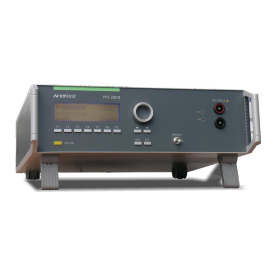
PFS 200N Series
Voltage Dips and Drop interruptions
PFS 200N30, N50, N100, N150, N200
Testing of electronic modules in 12V/24V or 42V supply
systems.
Short-term interruptions, micro dips and voltage drop out are
causing malfunctions in electronic modules. These phenomena
are simulated by the PFS 200N power fail generator.
The PFS 200 can be used as an individual instrument or can be
used in combination with all other generators of the series 200.
Version: 3.08 / 31.05.2017
Replaces: 3.07 / 26.02.2016
Filename: UserManual-PFS200Nx-E-V3.08
Printdate: 31.05.17
Daimler Chrysler
PF9326
Ford ES-XW7T
PSA B217110
Renault 36.00.808
Fiat 9.90110
Advertisement
Table of Contents


Need help?
Do you have a question about the PFS 200N Series and is the answer not in the manual?
Questions and answers