Table of Contents
Advertisement
the benchmark for emc
Manual
f o r
O p e r a t i n g
CNI 503 / CNI 501
3-phase coupling decoupling network
CNI 503x
CNI 503 A series
CNI 503 B series
1-phase coupling decoupling network
CNI 501x
Testing of electronic modules with EFT/burst, 1.2/50s Surge or
Ring Wave pulses up to 10kV, 5kA
The CNI 503 couples the surge and burst pulses from the
impulses generators UCS 500Nx to a three phase test object
(coupling as per. IEC or ANSI standard).
The CNI 503 is controlled from EM Test transient generator of
the Series 500 (UCS 500Nx, VCS 500Nx, EFT 500Nx).
Version: 3.32 / 28.06.2016
Replaces: 3.31 / 14.06.2016
Filename: UserManual-CNI503-E-V3.32.doc
Printdate: 28.06.16
Burst, Surge and
Ringwave Pulse as per.
– IEC 61000-4-4
– IEC 61000-4-5
– IEC 61000-4-12
– ANSI
Advertisement
Table of Contents

Related Manuals for EM TEST CNI 503 Series


Summary of Contents for EM TEST CNI 503 Series
- Page 1 – IEC 61000-4-12 (coupling as per. IEC or ANSI standard). – ANSI The CNI 503 is controlled from EM Test transient generator of the Series 500 (UCS 500Nx, VCS 500Nx, EFT 500Nx). Version: 3.32 / 28.06.2016 the benchmark for emc Replaces: 3.31 / 14.06.2016...
- Page 2 Switzerland Phone : +41 61 717 91 91 Fax : +41 61 717 91 99 URL : http://www.emtest.com Copyright © 2016 EM TEST (Switzerland) GmbH All right reserved. Specifications subject to change Manual of operation V 3.32 2 / 41...
-
Page 3: Table Of Contents
10.2. Calibration and Verification ......................... 31 10.2.1. Factory calibration .......................... 31 10.2.2. Guideline to determine the calibration period of EM Test instrumentation ........31 10.2.3. Calibration of Accessories made by passive components only: ............ 31 10.2.4. Periodically In-house verification ....................31 Delivery Groups ............................ - Page 4 EM TEST CNI 501 / CNI 503 Appendix ..............................33 12.1. Declaration of CE-Conformity ......................33 12.2. Connectors ............................34 12.2.1. 32 A plugs and connectors 4mm from Multi Contact ..............34 12.2.2. 100 A plugs and connectors 6mm from Multi Contact ..............34 12.2.3.
-
Page 5: List Of Coupling Networks
EM TEST CNI 501 / CNI 503 List of coupling networks 1.1. Coupling networks for IEC pulses Device Impulse Phase Supply rated Current ac Remarks CNI 501 5.5kV 250V 48V/32A dc CNI 501 S1 5.5kV 250V 100A 75V/100A dc CNI 503 A 5.5kV... -
Page 6: Coupling Networks As Per Iec, Ansi And Ringwave
EM TEST CNI 501 / CNI 503 1.2. Coupling networks as per IEC, ANSI and Ringwave Device Impulse Phase Supply rated Current ac Remarks CNI 503 B5 3x480V CNI 503 B7 3x480V RACK required CNI 503 B8 3x480V CNI 503 B9... -
Page 7: Special Coupling Networks
EM TEST CNI 501 / CNI 503 1.3. Special Coupling networks Device Impulse Phase Supply rated Current ac Remarks CNI 503 A.1 5.5kV 3x690V needs a UCS 500N5.2 CNI 503A S1 5.5kV 3x690V CNI 503A S2 5.5kV 3x690V CNI 503 A2.1 5.5kV... -
Page 8: Operating Functions
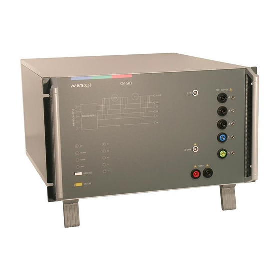
EM TEST CNI 501 / CNI 503 Operating Functions 2.1. Front view Figure 2.1: CNI 503 font view ( model for 4kV ) "TEST ON DUT Output L1/DC+, L2, L3, N/DC-, PE Switching ANSI -IEC Earth plug for EFT burst verification EFT output to HFK coupling clamp LED display Pulse (EFT / 50... -
Page 9: Rear Side
EM TEST CNI 501 / CNI 503 2.2. Rear side Figure 2.2: Rear side CNI 503 (4kV version) Figure 2.3: CNI 503 Rear side (> 4kV version) 1 EUT power L1, L2, L3 5 HV Input from generator 2 EUT power N... -
Page 10: Cni 501 S1
EM TEST CNI 501 / CNI 503 2.3. CNI 501 S1 Figure 2.3: Front side CNI 501 S1 with AC / DC switch Figure 2.4: CNI 501 S1 rear side Manual of operation V 3.32 10 / 41... -
Page 11: General
EM TEST CNI 501 / CNI 503 General The coupling network has to couple the transients well defined to the lines of a power supply system. The coupling is realized by discrete coupling capacitors, having a sufficient voltage capability and bandwidth. The specification is given in IEC 61000-4-4, IEC 61000-4-5, IEC 61000-4-12 and ANSI. -
Page 12: Technical Data Cni 503
EM TEST CNI 501 / CNI 503 Technical Data CNI 503 4.1. EUT power supply Pulse peak Coupling network EUT supply 50/60Hz Remarks voltage IEC, ANSI, Voltage Current ac/dc Ringwave 5.5kV CNI 501 1x250V dc 48V/32A CNI 501 S1 1x250V... -
Page 13: Dc Current Capability Of Cni 503Nx
EM TEST CNI 501 / CNI 503 4.2. DC current capability of CNI 503Nx CNI models with a built in ac mains contactor have a reduced dc switching capability. This current rate depends on the following parameters: contactor model applied dc voltage time constant L/R of the dc circuit The following list shows the dc current of the most models. -
Page 14: Technical Data Special Cni 503
EM TEST CNI 501 / CNI 503 4.3. Technical data special CNI 503 Differences to the standard CNI 503 devices: Device Based on Differences CNI503 B S7 CNI 503 B7 - 3x208 V; 400 Hz - Coupling capacitor surge = 1 F 7 kV 32 A - Inductance per phase = 160 H... -
Page 15: General
EM TEST CNI 501 / CNI 503 4.4. General DC supply as per tables in 4.2 Coupling modes Surge IEC 61000-4-5 Line to Ground all combinations coupling capacitor 9F Source impedance 12 Line to Line all combinations coupling capacitor 18F Source impedance 2... -
Page 16: Test Level With Burst As Per Iec 61000-4-4 Ed.2
EM TEST CNI 501 / CNI 503 4.5. Test level with Burst as per IEC 61000-4-4 Ed.2. Burst generators, which comply with the specifications of IEC 61000-4-4 Ed2: 2004, have a limitation of the maximum output voltage. Then the maximum test level is limited by the number of coupling on several lines. -
Page 17: Operation
EM TEST CNI 501 / CNI 503 Operation 5.1. Power supply input (EUT) The power supply input for the EUT is located at the rear side of the coupler. Adapters for customized three phase connectors have to be realized by the user himself or can be manufactured on customer’s specification. -
Page 18: Connection Of Dc Equipment
EM TEST CNI 501 / CNI 503 5.3. Connection of DC Equipment For the connection of DC power supplies following connections are provided. Polarity 3- Phase CNI 1- Phase CNI + Pole - Pole As DC input the terminals L1 and N must be used. These two plugs are marked at the rear side of with an additional plus or minus sign. -
Page 19: Operation With Cni Coupler Or Generator Internal Cdn
EM TEST CNI 501 / CNI 503 5.4. Operation with CNI coupler or generator internal CDN The coupling network CNI 503 is operated via the generator UCS / VCS / EFT and its operation panel or via ISM windows software. Only the different coupling modes can be changed or preselected. -
Page 20: Test Set Up
EM TEST CNI 501 / CNI 503 Test set up When setting up the test national and international regulations regarding human safety have to be guaranteed. All units, the surge generator, the EFT and the coupling matrix can be installed one above the other. -
Page 21: Grounding
EM TEST CNI 501 / CNI 503 6.1. Grounding 1. The coupling/decoupling network shall be connected as short as possible to the ground reference plane. Therefore the ground connector at the rear panel of the CDN shall be used. 2. The EFT generator has also to be connected as short as possible to the coupling matrix. -
Page 22: Surge Coupling To Cnv504 / 508 Network For Surge To Signal- And Data-Lines
EM TEST CNI 501 / CNI 503 6.2. Surge coupling to CNV504 / 508 network for surge to signal- and data-lines Connection of the surge coupling network for data lines to CNI 503 Coaxial cable COM: Banana cable Use a separate cable for the Ground... -
Page 23: Test Setup Cni 503 With Ucs500N5E And Ucs500N5V Generators
EM TEST CNI 501 / CNI 503 6.3. Test setup CNI 503 with UCS500N5E and UCS500N5V generators Figure 6.10: Setup and cabling Arrangement UCS500N5E next placed to the CNI 503. This allows the shortest possible cable for the EFT pulse from the generator to the CNI 503. -
Page 24: Test Setup Cni 501 / 503 With Eft 500/800 And Vcs 500 Generators
EM TEST CNI 501 / CNI 503 6.4. Test setup CNI 501 / 503 with EFT 500/800 and VCS 500 generators Figure 6.11: Example CNI 501 S1 100A for AC and DC Manual of operation V 3.32 24 / 41... -
Page 25: Test Setup With Cni 501 Bs3 Or Cni 503B7.5
EM TEST CNI 501 / CNI 503 6.5. test setup with CNI 501 BS3 or CNI 503B7.5 The generator UCS 500N7.6 controls either the 3-phase CNI 503B7.5 or 1-phase CNI 503BS3. The 1-phase CNI 501BS3 is installed outside the Test-rack on a table. Before testing, the following connections between the CNI 503B7.5 and CNI 503BS3 must be rearranged. -
Page 26: Ansi Coupling (Option)
EM TEST CNI 501 / CNI 503 ANSI Coupling (option) The option ANSI offers to change the coupling mode for surge tests between ANSI and IEC coupling To change the coupling mode to ANSI, it is necessary to press the button ANSI / IEC. -
Page 27: Cni 503 Rack Mountain
EM TEST CNI 501 / CNI 503 CNI 503 Rack Mountain Device Impulse Phase Supply rated Current ac/dc Remarks CNI 503 A3 5.5kV 3x480V requires MRAC or RAC CNI 503 A4 5.5kV 3x480V 100A requires MRAC or RAC requires MRAC or RAC... -
Page 28: Special Coupling Networks
EM TEST CNI 501 / CNI 503 Special coupling networks 9.1. CNI 501B9 9.1.1. Operating elements Figure 9.1: CNI 501B9 font view "TEST ON EFT input from UCS 500Mx Switching ANSI -IEC EUT Output L1/DC+, L2, L3, N/DC-, PE Earth plug for EFT burst verification LED display Pulse (EFT / 50... -
Page 29: Technical Data
EM TEST CNI 501 / CNI 503 9.1.2. Technical Data The general technical data are specified in chapter 4 EUT Supply AC Voltage 250 V, 50/60 Hz AC Current 100 A DC Voltage 75 V DC Current 100 A AC contactor... -
Page 30: Dc Application
EM TEST CNI 501 / CNI 503 9.1.4. DC Application Burst coupling as per IEC 61000-4-4 IEC 61000-4-4 All combinations “+”; “-“; PE, / (coupling to 50 ohm output) One coupling: “+” + “-“ + PE “+” & ”-“; “+”& PE; “-“N+PE Two couplings: Three couplings: “+”... -
Page 31: Maintenance And Calibration
EM TEST equipment. EM TEST doesn’t know each customer’s Quality Assurance Policy nor do we know how often the equipment is used and what kind of tests is performed during the life cycle of test equipment. Only the customer knows all the details and therefore the customer needs to specify the calibration interval for his test equipment. -
Page 32: Delivery Groups
EM TEST CNI 501 / CNI 503 Delivery Groups 11.1. Basic equipment Coupling network type CNI / CNV 503 xx Mains cable Mains cable for the EUT supply Manual on USB memory stick Calibration certificate ... -
Page 33: Appendix
EM TEST CNI 501 / CNI 503 Appendix 12.1. Declaration of CE-Conformity Manufacturer: EM TEST (Switzerland) GmbH Address: Sternenhofstr. 15 CH 4153 Reinach Switzerland Declares, that under is sole responsibility, the product’s listed below, including all their options, are conformity with the applicable CE directives listed below using the relevant section of the following EC standards and other normative documents. -
Page 34: Connectors
EM TEST CNI 501 / CNI 503 12.2. Connectors For general EUT connection to the rack 4/6 mm plug from Multi Contact are proposed. Below you find some information from the Multi Contact catalogue. For detail information please refer to http://www.multi-contact.com/ 12.2.1. -
Page 35: Multi Contact Mc Locking System (Ar-System)
EM TEST CNI 501 / CNI 503 MC Locking system (AR-system) 12.2.3. Multi Contact The MC Locking system (AR) operates on the “push-pull” principle. It is self – locking when connected. Disconnection is effected by an axially displaceable coupling ring: first push, then pull to disconnect. Dirty parts should be cleaned with industrial alcohol before connecting. -
Page 36: General Diagram
EM TEST CNI 501 / CNI 503 12.3. General diagram Coupling capacitors and resistors for power AC / DC lines Standard Coupling Coupling Coupling family capacitor resistor 2 Ω Line to line 18 µF 12 Ω Line to ground 9 µF 12 Ω... - Page 37 EM TEST CNI 501 / CNI 503 CNI 503A Models for 16 A/ 32 A with Test ON switch CNI 503A Models for 63A / 100A with Test ON switch Manual of operation V 3.32 37 / 41...
- Page 38 EM TEST CNI 501 / CNI 503 CNI 503B Models for 16 A/ 32 A with Test ON switch CNI 503B Models for 63A / 100A with Test ON switch Manual of operation V 3.32 38 / 41...
- Page 39 EM TEST CNI 501 / CNI 503 CNV 503 3x480V 16/32 A Only for surge pulses 32A models have 0.75mH inductors CNI 501 S1 100A (0.6mH inductors) Manual of operation V 3.32 39 / 41...
- Page 40 EM TEST CNI 501 / CNI 503 CNI 503A.1 3x690Vac 5.5kV, 16A CNI 503 A3.1 Manual of operation V 3.32 40 / 41...
-
Page 41: Inrush Current
EM TEST CNI 501 / CNI 503 CNI 503 A4.1, 3x440Vac, 5kV, 100A Overview 12.4. Inrush current The inrush current depends from the mains impedance, the inductance of the surge inductors and the EUT impedance. The inrush current in the tables below are max. theoretical values and cannot be reached in a real system.
Need help?
Do you have a question about the CNI 503 Series and is the answer not in the manual?
Questions and answers