Rohde ST 630 Operation Manual
Hide thumbs
Also See for ST 630:
- Manual (16 pages) ,
- Operating instructions manual (60 pages) ,
- Operation manual (331 pages)
Table of Contents
Advertisement
Available languages
Available languages
Quick Links
Bedienungsanleitung
Regelanlage ST 630/ST 632
Operation manual
Controller ST 630/ST 632
Mode d'emploi
Système de contrôle ST 630/ST 632
Operación manual
Sistema de control ST 630/ST 632
Manuale operativo
Sistema di controllo ST 630/ST 632
Handleiding
Controle systeem ST 630/ST 632
Návod k použití
Kontrolní systém ST 630/ST 632
ST 630/ST 632
Advertisement
Chapters
Table of Contents

Related Manuals for Rohde ST 630


Summary of Contents for Rohde ST 630
- Page 1 Bedienungsanleitung Regelanlage ST 630/ST 632 Operation manual Controller ST 630/ST 632 Mode d'emploi Système de contrôle ST 630/ST 632 Operación manual Sistema de control ST 630/ST 632 Manuale operativo Sistema di controllo ST 630/ST 632 Handleiding Controle systeem ST 630/ST 632 Návod k použití...
- Page 2 Sprachen | Languages | Langues | Idiomas | Lingue | Talen | Jazyky Bedienungsanleitung Regelanlage Deutsch ab Seite ST 630/ST 632 Instruction Manual English from page ST 630/ST 632 Notice d'utilisation système de contrôle Français de la page ST 630/ST 632 Operación manual sistema de control...
-
Page 3: Table Of Contents
Technische Informationen ..........................4 2.3. Überblick Regelanlage ............................5 2.4. Merkmale Stecker ............................. 6 2.4.1. CPC-14-Stecker (nur ST 630) ......................6 2.4.2. CPC-19-Stecker (nur ST 632) ......................6 2.5. Pinbelegung Stecker (ROHDE-Standard) ......................7 2.5.1. CPC-14-Stecker (nur ST 630) ......................7 2.5.2. - Page 4 ROHDEgraph ..............................40 10.4. ROHDE App myKiln ............................41 10.4.1. Allgemeine Informationen ........................ 41 10.4.2. Regler in der ROHDE App myKiln anmelden („Access code“) ............42 11. Störungen ..............................42 11.1. Sicherheitshinweise ............................42 11.2. Allgemeine Störungen ............................43 11.3.
-
Page 5: Einleitung
1.1. Vorwort Mit der Regelanlage ST 630/ST 632 haben Sie sich für eine hochwertige Steuerung für Ihren Ofen entschieden. Die Regelanlage ist durch die Verwendung neuester Technologien und stetiger Weiterentwicklung führend in dieser Klasse. Nach dem Durchlesen dieser Bedienungsanleitung sind Sie mit allen wichtigen Funktionen der Regelanlage ST 630/ST 632 vertraut. -
Page 6: Beschreibung Regelanlage
Beschreibung Regelanlage 2.1. Produktmerkmale ST 630/ST 632: • Mehrzonenregelung (1 bis 3 Zonen) der Ofenbeheizung • 32 Programme mit jeweils bis zu 32 Segmenten • 1 geregelte Aufheiz- bzw. Abkühlrampe und Haltezeit pro Segment • Haltezeiten bis zu 99:59 h •... -
Page 7: Überblick Regelanlage
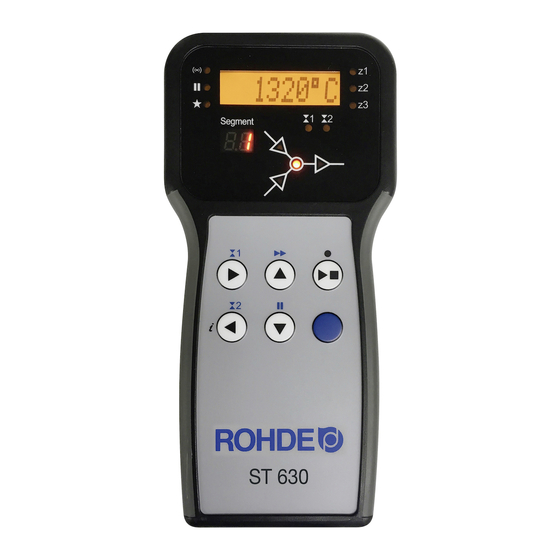
Anzeige „Heizzone 1/2/3 aktiv“ Kontrollanzeige „Datenübertragung“ Kontrollanzeige „Pause“ Kontrollanzeige „Aufheizen“ Anzeige Segment Kontrollanzeige Schaltausgang 1 (Event 1) und Schaltausgang 2 (Event 2) (bei ST 630 vorhanden, aber nicht aktiv) Grafisches Display und Programmverlauf Kontrollanzeige „Programm läuft“ Start-/Stopp-Taste Taste „Funktion“ Bedienelemente... -
Page 8: Merkmale Stecker
2.4. Merkmale Stecker 2.4.1. CPC-14-Stecker (nur ST 630) Die Regelanlage ST 630 wird über einen 14-poligen Stecker an den Ofen angeschlossen. Merkmale: • CPC-14-Stecker • 14-polige Steckschraubverbindung • Bajonettverschluss Die dafür vorgesehene schwarze 14-polige Steckdose befindet sich am Anschlusskasten des Ofens (in der Nähe der elektrischen Zuleitung). -
Page 9: Pinbelegung Stecker (Rohde-Standard)
2.5. Pinbelegung Stecker (ROHDE-Standard) 2.5.1. CPC-14-Stecker (nur ST 630) Bei 1-Zonen- und Mehrzonen-Brennöfen ohne zusätzliche Schaltausgänge (Events) werden die Regelanlagen mit dem CPC-14-Stecker am Ofen angeschlossen. Pin Nr. X = belegt Beschreibung Ansicht Pinbelegung am Stecker Thermoelement 1 + Thermoelement 1 -... -
Page 10: Schutzbeschaltung Ofenschütz
Die Spule eines Ofenschützes sollte mittels eines Varistors entstört werden. Dazu muss der Varistor an jedem Schütz, direkt über die Spulenklemmen angeschlossen werden. ROHDE Brennöfen werden standardmäßig so ausgeliefert. Für Öfen von Fremdherstellern, sind geeignete Produkte als Zubehör bei den Schütz-Herstellern erhältlich. -
Page 11: Montage
WARNUNG Vor schweren Personen- oder Sachschäden durch eine falsch platzierte Regelanlage. ⇒ Achten Sie darauf, dass die Regelanlage niemals auf dem Ofen abgelegt werden darf, sondern nur in der dafür vorgesehen Halterung positioniert werden sollte. WARNUNG Vor schweren Personen- oder Sachschäden durch eine falsch angeschlossene Regelanlage. -
Page 12: Verbindungskabel Anschließen
4.3. Verbindungskabel anschließen Schritt Beschreibung Ansicht Stecker Stecken Sie den Stecker der Regelanlage in die Steckdose am Ofen ein. Stecker und Steckdose haben eine geometrische Kodierung - Stecker und Steckdose passen nur in einer bestimmten Position ineinander. Die breite Nase am Stecker muss sich oben in 12-Uhr-Stellung befinden, um in die breite Aussparung am Stecker, ebenfalls in 12-Uhr-Stellung, zu passen. -
Page 13: Kurzanleitung
T/C: S • Der hier hinterlegte Typ muss dem des im Ofen verbauten Thermoelements entsprechen, d. h. Typ R, S, K oder N (ROHDE-Standard: Typ S). • Zuletzt wird die Ofentemperatur (Heizzone 1) auf dem Display angezeigt. 20 °C •... -
Page 14: Tastensperre
Anzeige im Brennbetrieb: Kontrollanzeige Anzeige Anzeige Heizzone Beschreibung links Hauptdisplay rechts Während des Brandes zeigt die Kontrollanzeige 100 °C „Aufheizen“ links vom Hauptdisplay, dass der Ofen aufheizt. Anzeige Segment: Displayanzeige Segment Beschreibung ° C Beim Einschalten des Reglers zeigt die Segmentanzeige die möglichen Temperatureinheiten im Betrieb an (°C/°F). -
Page 15: Temperaturanzeige Mehrzonen-Brennofen
6.3.2. Temperaturanzeige Mehrzonen-Brennofen Anzeige Anzeige Heizzone Beschreibung Hauptdisplay rechts Bei Mehrzonenöfen werden die Temperaturen der einzelnen Heizzonen angezeigt. Zone 1 erscheint standardmäßig beim Einschalten des Reglers. 20 °C Durch Drücken der Tasten oder kann die Ofentemperatur der anderen Heizzonen angezeigt werden. Die Bildsymbole der Zonennummern ändern sich entsprechend und zeigen an, welche Zonentemperatur gerade im Display erscheint. -
Page 16: Beispiel Brennprogramm Zur Erklärung Brennsegment
Anzeige Segment Grafisches Display & Programmverlauf Grafisches Display und Programmverlauf: Wert Bedeutung Grafisches Display und Programmverlauf Aufheizrampe Abkühlrampe Haltetemperatur (Zieltemperatur) Haltezeit ⇒ Je Brennsegment gibt es jeweils nur eine Aufheizrampe (1.1) oder eine Abkühlrampe (1.2) – niemals beides! 6.4.2. Beispiel Brennprogramm zur Erklärung Brennsegment Beispiel eines einfachen Brennprogramms, zur Erklärung der Brennsegmente und der Werte des Brennsegments: Brennsegment Werte des Brennsegments... - Page 17 Visualisierung des Beispiels: Ablauf Brennprogramm: • Der Temperaturanstieg erfolgt mit der eingegebenen, aufsteigenden Rampe (Aufheizen) [Heizrate], bis der Ofen die Halte- bzw. Zieltemperatur erreicht. • Nach Erreichen der Haltetemperatur verweilt der Ofen auf der Temperatur, für die eingestellte Haltezeit. • Danach führt der Regler das nächste Segment bis zum Programmende aus. •...
-
Page 18: Regelanlage Programmieren
6.5. Regelanlage programmieren 6.5.1. Brennprogramm verändern Kontroll- Anzeige Anzeige anzeige Heizzone Bedeutung Beschreibung Hauptdisplay links rechts • Wird kein Brand ausgeführt, dann leuchtet Kein Programm kein Element im Programmverlauf des im Betrieb grafischen Displays auf. 20 °C • Die Kontrollanzeige „Programm läuft“ leuchtet nicht auf. - Page 19 Kontroll- Anzeige Anzeige anzeige Heizzone Bedeutung Beschreibung Hauptdisplay links rechts • Durch erneutes Drücken der Taste erscheint die Haltezeit in „Stunden:Minuten“ Haltezeit auf dem Display. 00 : 15 • Mit den Tasten kann der Wert zwischen 00:00 h und 99:59 h geändert werden.
-
Page 20: Aufheizrampe In Abkühlrampe Ändern
6.5.2. Aufheizrampe in Abkühlrampe ändern Beim Verändern des Brennprogramms muss im Brennsegment häufig die Heizrate von einer Aufheizrampe in eine Abkühlrampe geändert werden. Aufheizrampe: Ist die Halte-/Zieltemperatur des ausgewählten Segments höher oder gleich, als die Halte-/Zieltemperatur des vorherigen Segments, zeigt der Regler eine Aufheizrampe im ausgewählten Segment an. Abkühlrampe: Ist die Halte-/Zieltemperatur des ausgewählten Segments niedriger, als die Halte-/Zieltemperatur des vorherigen Segments, zeigt der Regler eine Abkühlrampe im ausgewählten Segment an. -
Page 21: Abkühlrampe In Aufheizrampe Ändern
6.5.3. Abkühlrampe in Aufheizrampe ändern Beim Verändern des Brennprogramms muss im Brennsegment häufig die Heizrate von einer Abkühlrampe in eine Aufheizrampe geändert werden. Aufheizrampe: Ist die Halte-/Zieltemperatur des ausgewählten Segments höher oder gleich, als die Halte-/Zieltemperatur des vorherigen Segments, zeigt der Regler eine Aufheizrampe im ausgewählten Segment an. Abkühlrampe: Ist die Halte-/Zieltemperatur des ausgewählten Segments niedriger, als die Halte-/Zieltemperatur des vorherigen Segments, zeigt der Regler eine Abkühlrampe im ausgewählten Segment an. -
Page 22: Heizrate „Full" Programmieren
6.5.4. Heizrate „FULL“ programmieren Eine ungeregelte Vollast- Aufheizrampe/-Abkühlrampe („FULL“) kann programmiert werden. Displayanzeige Bedeutung Beschreibung Bemerkung Pr. 1 Das Brennprogramm wählen, Programmnummer siehe Abschnitt 6.5.1. welches verändert werden soll. Das Segment wählen, in dem die Anzeige im Aufheizrampe oder Abkühlrampe siehe Abschnitt 6.5.1. -
Page 23: Heizrate „End" Programmieren
6.5.5. Heizrate „END“ programmieren Um ein Brennprogramm zu beenden, muss im letzten Segment „END“ programmiert werden. Displayanzeige Bedeutung Beschreibung Bemerkung Pr. 1 Das Brennprogramm wählen, Programmnummer siehe Abschnitt 6.5.1. welches verändert werden soll. Das Segment wählen, in dem die Anzeige im Aufheizrampe oder Abkühlrampe siehe Abschnitt 6.5.1. -
Page 24: Parameter Für Schaltausgang Konfigurieren (Nur St 632)
7.2. Parameter für Schaltausgang konfigurieren (nur ST 632) Die zusätzlichen Schaltausgänge müssen in der Parameterkonfiguration eingestellt werden (siehe Abschnitt 12./ Parameter Nr. 45 und Nr. 49). Schaltausgang 1: Parameter Nr. 45 Schaltausgang 2: Parameter Nr. 49 ⇒ Den Schaltausgang in der Parameterkonfiguration zu aktivieren ist nur dann sinnvoll, wenn auch der Ofen über ein geschaltetes Ereignis verfügt –... -
Page 25: Schaltausgänge Programmieren (Nur St 632)
7.4. Schaltausgänge programmieren (nur ST 632) 7.4.1. Event/Ereignis programmieren (nur ST 632) Um einen Event/Ereignis im Brennprogramm hinzu programmieren zu können, muss vorher der zusätzliche Schaltausgang in der Parameterkonfiguration (siehe Abschnitt 12./Parameter Nr. 45 oder Nr. 49) auf Wert „1“ festgelegt werden. -
Page 26: Temperaturgesteuerte Abluftklappe Programmieren (Nur St 632)
⇒ Wenn der Wert „2“ für den Parameter Nr. 45 nicht eingestellt wird, wird das falsche Konfigurationsmenü dargestellt. ⇒ In diesem Betriebsmodus muss die temperaturgesteuerte Abluftklappe zum Beginn des Programms geöffnet sein. (ROHDE-Standard). Bei Bedarf (Fremdofen) die Verschaltungslogik des Abluftklappenantriebs umkehren. Anmerkung: 1. Wird 30 Sekunden lang keine Taste gedrückt, verlässt die Steuerung automatisch das Konfigurationsmenü... -
Page 27: Temperaturgesteuertes Kühlsystem Programmieren (Nur St 632)
Schritt Displayanzeige Beschreibung Bemerkung 632°C Taste zur Bestätigung der Eingabe drücken. DAMPER:O Das Menü für die Öffnungstemperatur der Abluftklappe wird angezeigt. Letzte festgelegte 700°C Öffnungstemperatur der Taste drücken. Abluftklappe wird angezeigt. Die Öffnungstemperatur für die Zur schnelleren Eingabe können die 702°C Abluftklappe durch Drücken der Tasten auch gedrückt gehalten... - Page 28 HINWEIS Der Brennofen muss ab Werk für die Verwendung eines Kühlsystems mittels Gebläse oder Lüfter vorbereitet sein. ⇒ Von einer Nachrüstung, eines Kühlsystems mittels Gebläse oder Lüfter, in einen Brennofen ohne Kühlsystem wird generell abgeraten. ⇒ Öfen mit Kühlsystem, sind vom Hersteller speziell für Anwendung mit Kühlsystem vorbereitet und gefertigt.
-
Page 29: Hinweise Zur Bedienung
Ablauf des temperaturgesteuerten Lüfter-Betriebs bei Brennbetrieb: Beschreibung Ablauf Kontrollanzeige Vor dem Brennbetrieb und während des Brennbetriebs ist das Kühlsystem mittels Lüfter ausgeschaltet. Das Kühlsystem schaltet sich nach dem Brennbetrieb während der Abkühlphase ein, wenn der Ofen die eingegebene Starttemperatur des Lüfters erreicht hat. Das Kühlsystem bleibt eingeschaltet, bis die Ausschalttemperatur erreicht wird. -
Page 30: Bedienung Über Taste J
8.1.2. Bedienung über Taste • Ein Drücken der Taste während des Brandes bricht den Brennvorgang ab (keine Pause). • Ein erneutes Drücken der Taste startet den Brennvorgang erneut, aber von Beginn an. • Ist die aktuelle Ofentemperatur höher als die erforderliche Haltetemperatur, übernimmt der Regler automatisch das Abkühlen von der aktuellen Ofentemperatur auf die Haltetemperatur. -
Page 31: Programm-Pause-Funktion
8.1.5. Programm-Pause-Funktion WARNUNG Vor schweren Sachschäden durch eine zu lange Haltezeit, nach Benutzung der ProgrammPause-Funktion. ⇒ Zu langes Halten bei hohen Temperaturen kann den Ofen beschädigen. ⇒ Mit der ProgrammPause-Funktion pausiert das Programm, die Temperatur wird im Ofen trotzdem weiter gehalten! ⇒... -
Page 32: Abkühlen
• Informationen zur errechneten Energiemenge: In Abständen von 30 Sekunden (werkseitig eingestellt) berechnet der Regler die vom Brennofen benötigte Energiemenge . Wird beispielsweise 40 % der vollen Leistung benötigt, um eine bestimmte Heizrate oder eine Haltetemperatur aufrecht zu erhalten, erfolgt die Steuerung der Energiezufuhr in Abständen von 30 Sekunden für eine Dauer von 12 Sekunden. -
Page 33: Allgemeine Bedienungshinweise
8.3. Allgemeine Bedienungshinweise 8.3.1. Ofen heizt/kühlt zu langsam • Bei zu hoch eingegebenem Temperaturanstieg, welchem der Ofen nicht folgen kann, geht die Regelanlage in Volllast und setzt erst mit der nächsten Rampe oder mit dem nächsten Haltesegment fort, sobald der Ofen die gewünschte Temperatur erreicht hat. -
Page 34: Anpassen Der Brennwerte Im Laufenden Brand
8.3.5. Anpassen der Brennwerte im laufenden Brand Während des Programmverlaufs können mit dem Regler bestimmte Brennwerte verändert werden: • Mit Taste den gewünschten Parameter während des Brennvorgangs auswählen. • Der Parameter wird entsprechend im Programmverlauf auf dem grafischen Display durch ein blinkendes Bildsymbol angezeigt. -
Page 35: Allgemeine Fehlermeldungen
Regler zu nahe am Ofen montiert Bitte wenden Sie sich an Ihren ERROR: 8 Interner ADU-Fehler (Analog-Digital-Umsetzer) Fachhändler oder an den ROHDE Service Die Temperaturdifferenz zwischen Gilt nur für Mehrzonen-Brennöfen: ERROR: 9 Heizzone 2 bzw. 3 und Heizzone 1 Maximal zulässige Temperaturdifferenz zwischen... -
Page 36: Fehlermeldung Des Brennprogramms
Hinweis: • Jede der aufgeführten Fehlermeldungen führt zum Abbruch des Brennvorgangs. • Der Abbruch des Brennvorgangs soll den Ofen vor Schäden schützen. • Ein Alarm wird einmal pro Sekunde ausgegeben. • Den Regler vor einem Neustart von der Stromversorgung trennen und eine Elektrofachkraft oder den Servicetechniker mit der Überprüfung des Problems beauftragen. -
Page 37: Eigenschaften Der Schnittstelle
10.1.2. Eigenschaften der Schnittstelle Allgemeiner Sicherheitshinweis: VERBOT Schließen sie keine anderen Geräte, außer einen USB-Stick, an dieser USB-Schnittstelle ⇒ An dieser USB-Schnittstelle dürfen keine Geräte, wie Handys oder Laptop, zum Laden des Akkus angesteckt werden. Beschreibung: • Für die Erfassung der Messwerte eignen sich USB-Versionen 1.0 oder 2.0. •... -
Page 38: Echtzeituhr-Funktion
10.1.5. Echtzeituhr-Funktion • Im Modul zur Messwerterfassung ist eine batteriegepufferte Echtzeituhr für die Datums- und Uhrzeitanzeige verbaut. • Schaltjahre werden berücksichtigt. • Die Umstellung von der Sommer- auf die Winterzeit muss manuell durchgeführt werden. • Mit der Echtzeituhr-Funktion können Messwertdaten und Dateien mit Datum und Zeitstempel versehen werden. •... -
Page 39: Messwerterfassung
10.1.7. Messwerterfassung • Die Erfassung der Messwerte beginnt, sobald der Brennvorgang startet. • Diese endet, sobald der Ofen nach dem Abkühlen eine Temperatur von 100 °C (automatischer Programmstopp) erreicht oder das Programm mit Taste beendet wird (erzwungener Programmstopp). • Auf dem USB-Stick wird die Datei „LOGxyz.CSV“ erzeugt. •... -
Page 40: Speichern Auf Usb-Stick
10.2.2. Mögliche Funktionen mit W-LAN Mittels W-LAN Verbindung können verschiedene Funktionen zwischen Regelanlage (Ofen) und einem Computer, Tablet oder Smartphone ausgeführt werden. Die W-LAN Verbindung wird hauptsächlich zur Nutzung von ROHDE App myKiln verwendet (siehe Abschnitt 10.4.) Mögliche Funktion: • Erfasste Messwerte des Reglers können drahtlos zur Auswertung an einen Computer, Tablet oder Smartphone gesendet werden. -
Page 41: Verbindung Über Einen W-Lan Router (Wps-Funktion) Herstellen
10.2.4. Verbindung über einen W-LAN Router (WPS-Funktion) herstellen Regelanlage direkt mit einem W-LAN (WIFI) verbinden: Schritt Beschreibung Ablauf Bemerkung Regelanlage ausschalten. Taste drücken und die Regelanlage Taste während des Einschaltens gedrückt halten. einschalten. Taste gedrückt halten, bis im Hauptdisplay „PAIRING“ erscheint. -
Page 42: Rohdegraph
Schritt Beschreibung Ablauf Bemerkung Ignorieren Sie folgende Warnungen Ihres Computers, Tablet oder Smartphones: Kein Internet verfügbar. Dieses W-LAN Netzwerk hat keinen Internetzugriff. Verbinden Sie das Gerät mit dem Trotzdem verbinden. Ungesichertes Netzwerk. Drahtlosnetzwerk namens „Controller“. Verbindungsprozess mit dem WIFI kann etwas länger dauern. -
Page 43: Rohde App Mykiln
10.4. ROHDE App myKiln 10.4.1. Allgemeine Informationen Die Anwendung ROHDE App myKiln ist eine App-basierende Software zur Visualisierung und Archivierung von Brennkurven aus den erfassten Messwerten der Regelanlage und zur Erstellung, Bearbeitung oder Verwaltung. Account Einen kostenlosen Account erstellen und den Regler dort mit dem erstellen Access code anmelden. -
Page 44: Regler In Der Rohde App Mykiln Anmelden („Access Code")
Regler in der ROHDE App myKiln anmelden („Access code“) Um den Regler in der ROHDE App myKiln anzumelden, wird der „Access code“ des Reglers benötigt. Der „Access code“ befindet sich auf der Rückseite des Reglers. Jeder Regler mit einem integrierten Modul zur drahtlosen Datenübertragung hat einen eigenen „Access code“. -
Page 45: Allgemeine Störungen
11.3. Spezielle Störung: Sicherung Regelanlage ersetzen Falls die Regelanlage nicht eingeschaltet werden kann und andere Störungen ausgeschlossen sind, ersetzen Sie die Schmelzsicherung im Gehäuse der Regelanlage. Benötigtes Ersatzteil: Feinsicherung 3.15 A T ROHDE Artikel-Nr. 704851 Sicherung ersetzen: Schritt Tätigkeit Bemerkung Regelanlage ausschalten. - Page 46 Schmelzsicherung Typ: Neue Sicherung einsetzen. Feinsicherung, 3,15 A T, 5 mm x 20 mm ⇒ Die Sicherung kann in beide Richtungen eingesetzt werden. ROHDE Artikel-Nr.: 704851 Schmelzsicherung in umgekehrter Reihenfolge Werkzeug: wieder einbauen. Schraubendreher Schlitz 7 mm Verbindungskabel der Regelanlage am Ofen anschließen.
-
Page 47: Parameterkonfiguration
12. Parameterkonfiguration 12.1. Verfügbare Parameter In der Regelanlage können verschiedene Betriebsparameter frei geändert werden. Parameter- Min. Werks- Funktion Parameter Beschreibung Wert Wert Wert einstellung 1 Einheit = 0,1 kW z. B.: ⇒ Für einen Ofen mit 1 Heizzone und Leistung Heizzone 1: 10 kW Gesamtleistung den Wert Anzeige der Ofenleistung, 9999... -
Page 48: Parameter Verändern
12.2. Parameter verändern Schritt Displayanzeige Beschreibung Bemerkung Regelanlage ausschalten Bei älteren ST 630 muss nur die Taste < ROHDE Tasten drücken und gedrückt und gleichzeitig die Regelanlage gleichzeitig Regelanlage einschalten. eingeschalten werden. ⇒ Der Thermoelement-Typ wird nur < Tasten solange gedrückt... -
Page 49: Beispiele Für Brennprogramme
13. Beispiele für Brennprogramme 13.1. Programmbeispiele (Keramik) Beschreibung Einbrand 100 °C/h 1050 °C 00 h:00 min FULL/SKIP 1050 °C 01 h:30 min 1050 °C Schrühbrand 60 °C/h 600 °C 00 h:00 min 950 °C 00 h:00 min 950 °C Irdenware 150 °C/h 900 °C 00 h:00 min... -
Page 50: Entsorgung Regelanlage
Reinigungsanweisungen: ⇒ Verunreinigungen mit einem sauberen und trockenen Lappen entfernen. ⇒ Keine Reinigungsmittel benutzen. ⇒ Regelanlage niemals nass mit Wasserstrahl oder Hochdruckreiniger abspritzen. ⇒ Keine Pressluft zur Reinigung verwenden. 15. Entsorgung Regelanlage Die Regelanlage muss am Ende der Lebensdauer ordnungsgemäß entsorgt werden. -
Page 51: Konformitätserklärung
Die alleinige Verantwortung für die Ausstellung dieser Konformitätserklärung trägt der Hersteller des nachfolgend beschriebenen Produkts. Beschreibung und Identifizierung Produkt: Regelanlage Modell: ST 630/ST 632 Zweck: Steuerung von Brennöfen für Haushalt, Gewerbe und Leichtindustrie Ferner wird erklärt, dass die speziellen technischen Unterlagen erstellt wurden. Die Schutzziele der folgenden weiteren EU-Richtlinien werden erfüllt: 2014/30/EU Richtlinie über elektromagnetische Verträglichkeit... - Page 52 Technical information ............................53 2.3. Control unit overview ............................54 2.4. Connector features ............................55 2.4.1. CPC 14 connector (ST 630 only) ..................... 55 2.4.2. CPC 19 connector (ST 632 only) ..................... 55 2.5. Plug pin assignment (ROHDE default) ......................56 2.5.1.
- Page 53 ROHDEgraph ..............................87 10.4. ROHDE app myKiln ............................87 10.4.1. General informationen ........................87 10.4.2. Register the controller in ROHDE app myKiln (“Access code”) ............88 11. Faults ................................88 11.1. Safety instructions ............................88 11.2. General faults ..............................89 11.3.
-
Page 54: Introduction
1.1. Preface You have chosen an ST 630/ST 632 controller, a high-quality product for your kiln. This controller series incorporates the latest technological features, is being continuously developed and is the leader in its class. After reading this instruction manual, you will be familiar with the functionality of the ST 630/ST 632 controller. -
Page 55: Control Unit Description
Control unit description 2.1. Product features ST 630/ST 632: • Multi-zone control of the kiln heating (1 to 3 zones) • 32 programs with up to 32 segments each • 1 controlled heating/cooling ramp + soak per segment • Soak times up to 99 hours 59 mins •... -
Page 56: Control Unit Overview
“Data transfer” indicator “Pause“ indicator “Kiln heating up” indicator Segment indicator Switch output 1 (event 1) and switch output 2 (event 2) indicator (present with ST 630, but not active) Graphical program operation display “Program running” indicator Start/stop key “Function“ key... -
Page 57: Connector Features
2.4. Connector features 2.4.1. CPC 14 connector (ST 630 only) The control unit ST 630 is connected to the kiln via a 14-pin connector. Features: • CPC 14 connector • 14-pin screw connection • Bayonet fitting The black 14-pin socket provided for this is located on the switch cabinet of the kiln (near the electrical supply line). -
Page 58: Plug Pin Assignment (Rohde Default)
2.5. Plug pin assignment (ROHDE default) 2.5.1. CPC 14 connector (ST 630 only) Single and multi-zone kilns without additional switch outputs (events) are connected by a CPC 14 connector. Pin no. X = Used Description Pin assignment Thermocouple 1 +... -
Page 59: Kiln Contactor Protection Circuit
The coil of each kiln contactor should be suppressed with an RC circuit. RC circuits must be connected directly across the coil terminals on each contactor. ROHDE kilns are delivered this way as standard. For kilns from other manufacturers, suitable products are available as accessories from contactor manufacturers. -
Page 60: Mounting
WARNING An incorrectly placed control unit can lead to serious personal injury or property damage. ⇒ The control unit should never be placed on the kiln but should only be positioned in the bracket provided for it. WARNING An incorrectly connected control unit can lead to serious personal injury or property damage. -
Page 61: Connecting The Connection Cable
4.3. Connecting the connection cable Step Description Insert the plug of the control unit into the socket on the kiln. The plug and socket have a geometric coding – the plug and socket only fit together in one position. The wide lug on the plug must be at the top in the 12 o’clock position to fit into the wide recess on the plug, also in the 12 o’clock position. -
Page 62: Quick Start Guide
Main display zone display Description on the left on the right • After switching on, the controller carries out a ROHDE display test. • All indicators light up. • The controller will sound a short beep. • The controller displays the version number of the integrated software. -
Page 63: Keylock
Display in firing mode: Indicator on Heating zone Main display Description the left display on the right 100 °C During the firing, the “Heating” indicator to the left of the main display shows that the kiln is heating up. Segment display: Display screen segment Description °... -
Page 64: Temperature Display For Multi Zone Kilns
6.3.2. Temperature display for multi zone kilns Heating zone display Main display Description on the right In the case of multi-zone kilns, the temperatures of the individual heating zones are displayed. Zone 1 is displayed by default when the controller is powered on. 20 °C The kiln temperature of the other heating zones can be displayed by pressing the... -
Page 65: Example Of A Firing Program To Illustrate The Firing Segment
Segment display Gaphical program & operation display Graphical program operation display: Value Meaning Graphical program operation display Heating ramp Cooling ramp Soak Temperature (target temperature) Soak time ⇒ There is only either one heating ramp (1.1) or one cooling ramp (1.2) per firing segment - never both! 6.4.2. - Page 66 Visualisation of the example: Firing program (firing curve) Firing program sequence: • The temperature rises at the entered, ascending ramp (heating up) [ramp rate] until the kiln reaches the soak or target temperature. • It then soaks (dwells) at the soak temperature for the soak period. •...
-
Page 67: Programming The Control Unit
6.5. Programming the control unit 6.5.1. Changing the firing program Indicator Heating on the Main display zone display Meaning Description left on the right • If no firing is carried out, no element lights up in the program sequence of the No program graphical display. -
Page 68: Changing A Heating Ramp Into A Cooling Ramp
Indicator Heating on the Main display zone display Meaning Description left on the right The next press of the key increments the segment number digit and firing values for the next segment can be entered. Indicator in the segment display ⇒... -
Page 69: Changing A Cooling Ramp Into A Heating Ramp
Changing a heating ramp to a cooling ramp: Display Meaning Description Remark Pr. 1 Program Select the firing program that is to See Section 6.5.1. number be changed. Select the segment with the heating Indicator in the ramp to be changed into a cooling See Section 6.5.1. -
Page 70: Programming The "Full" Ramp Rate
Changing a cooling ramp to a heating ramp: Display Meaning Description Remark Pr. 1 Program Select the firing program that is to See Section 6.5.1. number be changed. Select the segment with the cooling Indicator in the ramp to be changed into a heating See Section 6.5.1. -
Page 71: Programming The "End" Ramp Rate
6.5.5. Programming the “END” ramp rate To end a firing program, “END” must be programmed in the last segment. Display Meaning Description Remark Pr. 1 Program Select the firing program that is to See Section 6.5.1. number be changed. Indicator in the Select the segment with the segment heating ramp to be changed into... -
Page 72: Configuring Parameters For Switch Output (St 632 Only)
7.2. Configuring parameters for switch output (ST 632 only) The additional switch outputs must be set in the parameter configuration (see section 12. / parameter no. 45 and 49). Switch output 1: parameter no. 45 Switch output 2: parameter no. 49 ⇒... -
Page 73: Program Switch Outputs (St 632 Only)
7.4. Program switch outputs (ST 632 only) 7.4.1. Event programming (ST 632 only) To be able to program an event in the firing program, the additional switch output must first be set to “1” in the parameter configuration (see Section 12. / Parameter no. 45 or 49). Programming procedure: When programming a ramp or a soak period –... -
Page 74: Programming A Temperature-Controlled Exhaust Air Flap (St 632 Only)
⇒ If parameter no. 45 has not been set to “2”, the wrong configuration menu is displayed. ⇒ In this operating mode, the temperature-controlled exhaust air flap must be open at the beginning of the program (ROHDE default). If necessary, (for a third-party kiln) reverse the interconnection logic of the exhaust air flap drive. -
Page 75: Programming The Cooling System (St 632 Only)
Step Display Description Remark 632°C Press the key to confirm the entry. DAMPER:O The menu for the exhaust air flap opening temperature is displayed. 700°C The last set exhaust air flap opening Press the key. temperature is displayed. Enter the exhaust air flap opening 702°C The keys can also be held down for temperature by pressing the... - Page 76 NOTE The kiln must be prepared at the factory for the use of a cooling system with a blower or fan. ⇒ Retrofitting a cooling system with a blower or fan in a kiln without a cooling system is generally not recommended. ⇒...
-
Page 77: Instructions For Use
Procedure for fan operation in firing mode: Description Indication The fan cooling system is switched off before and during the firing operation. The cooling system switches on after firing, during the cooling phase when the kiln reaches the specified start temperature. The cooling system remains switched on until the switch-off temperature has been reached. -
Page 78: Operation Using The J
8.1.2. Operation using the • If the key is pressed during firing, it will be halted (not paused). • Pressing the key again will restart the firing from the beginning. • The controller will look at the current kiln temperature and if this is greater than the required soak temperature then it will automatically cool from the current temperature to the soak temperature. -
Page 79: Notes On The Firing Process
Operation: Step Description Remark The controller sounds a short beep, the The program pause facility is activated by Activating the program current program is paused and the < pause facility pressing the key and then the key. current kiln temperature is maintained. The program pause is ended by pressing Ending program pause The paused firing program continues. -
Page 80: Cooling
8.2.2. Cooling Upon completion of firing the controller lights all LEDs on the graphical display. ⇒ The kiln is switched off and begins to cool down on its own. Displays during the cooling phase: Display 1 Display 2 Description As long as the kiln temperature is above 40 °C, the display alternates 100°C HOT! between display 1 &... -
Page 81: Introduction Of Cooling Air In Cooling Ramps
8.3.3. Introduction of cooling air in cooling ramps NOTE The introduction of cooling air using a blower or fan at a firing chamber temperature of more than 600°C can damage the insulating material or heating elements. ⇒ Cold air may only be brought in at a temperature below 600°C. ⇒... -
Page 82: General Error Messages
The maximum duration of the firing process ⇒ Deactivated at the factory. exceeded. ⇒ If you want to set a maximum firing time, please contact ROHDE Service. • The internal temperature of the controller has exceeded a factory-set limit value. -
Page 83: Firing Program Errors
Note: • Each of the listed error messages leads to the termination of the firing process. • Terminating the firing process protects the kiln from damage. • The alarm buzzer will sound once per second. • To reset the controller, turn off the power to the device and have the fault investigated and rectified by your installer or kiln service engineer. -
Page 84: Interface Properties
10.1.2. Interface properties General safety note: PROHIBITION Do not connect any other devices, except a USB flash drive, to this USB interface. ⇒ No devices such as cell phones or laptops may be plugged into this USB interface to charge the battery. Description: •... -
Page 85: Real-Time Clock Function
10.1.5. Real-Time clock function • This data logger module incorporates an accurate battery-backed real-time clock to display the date and time of day. • It compensates for leap years. • It does not automatically compensate for daylight saving in summer and winter. •... -
Page 86: Data Logging
10.1.7. Data logging • Data logging commences when a firing is started. • It finishes when the firing is complete and when the kiln has cooled to 100°C. • The “LOGxyz.CSV” file is generated on the USB flash drive. • The first file created will be “LOG000.CSV”. •... -
Page 87: Saving On Usb Flash Drive
• Measured values recorded by the controller can be sent wirelessly to a computer, tablet or smartphone for evaluation. • The kiln operation can be observed and monitored in real-time from a computer, tablet or smartphone (ROHDE app myKiln). • Firing program data can be loaded onto the controller using ROHDE app myKiln. -
Page 88: Establishing Connection Manually With A Wireless Router
10.2.5. Establishing connection manually with a wireless router Process to manually connect the control unit to a wireless network using a computer, tablet or smartphone: Step Description of the process Remark Switch the control unit off. Press the key and switch on the control Hold down the key while switching on. -
Page 89: Rohdegraph
10.4. ROHDE app myKiln 10.4.1. General informationen ROHDE app myKiln is an application for the visualisation, archiving, creation, editing or managing of firing curves from the recorded measured values of the control system. Create an Create a free account and register the controller there with the account “Access code”. -
Page 90: Register The Controller In Rohde App Mykiln ("Access Code")
Register the controller in ROHDE app myKiln (“Access code”) To register the controller in ROHDE app myKiln, the controller's “access code” is required. This “access code” is located on the back of the controller. Each controller with an integrated module for wireless data transmission has its own unique “access code”. -
Page 91: General Faults
If the control unit cannot be switched on and other faults have been excluded, replace the fuse in the housing of the control unit. Required spare part: 3.15 A T micro-fuse ROHDE item no.: 704851 Replacing the fuse: Step Activity Remark Switch the control unit off. - Page 92 Fuse type: Insert a new fuse. 5 x 20 mm / 3.15 A T micro-fuse ⇒ The fuse can be inserted in both directions. ROHDE item no.: 704851 Tool: Reinstall the fuse in reverse order. 7 mm slotted screwdriver Connect the control unit connection cable to the kiln.
-
Page 93: Parameter Configuration
12. Parameter configuration 12.1. Available parameters Various operating parameters can be freely changed in the control system. Parameter Min. Max. Default Parameter function Description of the value value value setting 1 unit = 0.1 kW E.g.: ⇒ For a kiln with 1 heating zone and a total output of 10 kW (see kiln Heating zone 1 output: nameplate), enter the value “100”... -
Page 94: Changing Parameters
12.2. Changing parameters Step Display Description Remark Switching the control unit off With older ST 630 controllers, you only ROHDE < Press the keys and switch on have to press the key and switch on the the control system at the same time. -
Page 95: Example Of A Firing Program
13. Example of a firing program 13.1. Program examples (ceramics) Initial firing 01 h:30 100°C/h 1050°C 00 h:00 min FULL/SKIP 1050°C 1050°C Biscuit firing 00 h:00 60°C/h 600°C 00 h:00 min 950°C 950°C Earthenware 00 h:30 150°C/h 900°C 00 h:00 min 1050°C 1050°C High-... -
Page 96: Disposal Of The Control Unit
Cleaning instructions: ⇒ Remove contamination with a clean, dry cloth. ⇒ Do not use detergents. ⇒ Never spray the control systems with a water jet or high-pressure cleaner. ⇒ Never use compressed air. 15. Disposal of the control unit The control unit must be properly disposed of at the end of its service life. Electrical equipment must never be disposed of with general or household waste. -
Page 97: Declaration Of Conformity
Description and identification Product: Control unit Model: ST 630/ST 632 Purpose: Control of kilns for household, commercial and light industrial use We also declare that the special technical documents were created. The protection goals of the following additional EU directives have been met:... - Page 98 2.3. Vue d'ensemble du système de régulation..................... 100 2.4. Caractéristiques du connecteur ........................101 2.4.1. Connecteur CPC 14 (seulement ST 630) ..................101 2.4.2. Connecteur CPC 19 (seulement ST 632) ..................101 2.5. Brochage du connecteur (Standard ROHDE) ....................102 2.5.1.
- Page 99 10.4. ROHDE app myKiln ............................138 10.4.1. Informations d'ordre général ......................138 10.4.2. Inscrire le régulateur dans ROHDE app myKiln (« Access code ») ..........139 11. Dérangements .............................. 139 11.1. Consignes de sécurité ........................... 139 11.2. Dérangements d'ordre général ........................140 11.3.
-
Page 100: Introduction
Avant-propos En optant pour le système de régulation ST 630/ST 632, vous avez choisi une commande haut de gamme pour votre four. Grâce à la mise en œuvre des technologies les plus récentes et à un perfectionnement continu, ce système de régulation est à... -
Page 101: Description Du Système De Régulation
Description du système de régulation 2.1. Caractéristiques du produit ST 630/ST 632 : • Régulation multi-zones (1 à 3 zones) du chauffage du four • 32 programmes avec jusqu'à 32 segments chacun • 1 rampe de chauffage ou de refroidissement régulée avec temps de maintien par segment •... -
Page 102: Vue D'ensemble Du Système De Régulation
Affichage de segment Indicateur de contrôle « Sortie de commande 1 (Event 1) et sortie de commande 2 (Event 2) » (disponible avec ST 630, mais non actif) Afficheur graphique et déroulement du programme Indicateur de contrôle « Programme en cours »... -
Page 103: Caractéristiques Du Connecteur
Caractéristiques du connecteur 2.4.1. Connecteur CPC 14 (seulement ST 630) Le système de régulation ST 630 se raccorde au four par le biais d'un connecteur à 14 pôles. Caractéristiques : • Connecteur CPC 14 • Connecteur 14 pôles à enficher et visser •... -
Page 104: Brochage Du Connecteur (Standard Rohde)
2.5. Brochage du connecteur (Standard ROHDE) 2.5.1. Connecteur CPC 14 (seulement ST 630) Les fours mono-zone et multi-zones sans sorties de commutation (events) supplémentaires se raccordent au régulateur au moyen du connecteur CPC 14. Broche n° X = affectée Description... -
Page 105: Circuit De Protection Du Contacteur De Four
La bobine d'un contacteur de four devrait être déparasitée au moyen d'un circuit RC. À cet effet, le circuit RC doit être raccordé directement à chaque contacteur via les bornes de bobine. Les fours ROHDE sont systématiquement livrés avec cette protection. Pour les fours d'autres fabricants, des produits adéquats sont disponibles comme accessoires auprès des fabricants de contacteurs. -
Page 106: Montage
AVERTISSEMENT Risque de dommages corporels graves ou de dégâts matériels dus à un système de régulation mal placé. ⇒ Gardez à l'esprit que le système de régulation ne doit jamais être posé sur le four, mais exclusivement placé dans le support prévu à cet effet. AVERTISSEMENT Risque de dommages corporels graves ou de dégâts matériels dus à... -
Page 107: Raccordement Du Câble De Connexion
4.3. Raccordement du câble de connexion Étape Description Insérez le connecteur du système de régulation dans la prise du four. Le connecteur et la prise présentent un codage géométrique : l'insertion du connecteur dans la prise ne peut se faire qu'à une position définie. L'ergot large du connecteur doit se trouver en haut à... -
Page 108: Guide Rapide
Le type de thermocouple mémorisé ici doit correspondre à celui du thermocouple intégré dans le four, c.-à-d. type R, S, K ou N (Standard ROHDE type S). • L'afficheur indique en dernier la température du four. (Zone de chauffe 1) 20 °C... -
Page 109: Verrouillage Des Touches
Indication Indicateur Indication zone de Étape de contrôle afficheur Description chauffe à gauche principal à droite 19 °C Les touches permettent d'afficher la température du four des autres zones de chauffe (fonction disponible si le régulateur a été configuré pour les fours multi-zones). 21 °C Affichage pendant la cuisson : Indicateur de... -
Page 110: Affichage De Température
6.3. Affichage de température 6.3.1. Affichage de température sur four mono-zone Indication Indication afficheur zone de chauffe Description principal à droite Sur un four mono-zone, c'est toujours la température pour la zone de chauffe 1 qui est indiquée. 20 °C ⇒... -
Page 111: Segments De Cuisson
6.4. Segments de cuisson 6.4.1. Explication des segments de cuisson Chaque programme de cuisson se compose de plusieurs segments de cuisson. Chaque segment de cuisson comprend 3 valeurs. Les 3 valeurs d'un segment de cuisson sont : • une rampe de chauffage (1.1) ou une rampe de refroidissement (1.2) •... -
Page 112: Exemple De Programme De Cuisson Expliquant Ce Que Signifie Segment De Cuisson
6.4.2. Exemple de programme de cuisson expliquant ce que signifie segment de cuisson Exemple de programme de cuisson simple, pour expliquer les segments de cuisson et leurs valeurs associées : Segment de Valeurs du segment de cuisson Description des valeurs cuisson Départ différé... - Page 113 Déroulement du programme de cuisson : • La montée en température s'effectue à la rampe croissante paramétrée (chauffe) [vitesse de chauffe] jusqu'à ce que le four atteigne la température de maintien ou la température cible. • Une fois la température de maintien atteinte, le four reste à cette température pendant le temps de maintien paramétré.
-
Page 114: Programmation Du Système De Régulation
6.5. Programmation du système de régulation 6.5.1. Modification du programme de cuisson Indicateur Indication Indication de contrôle afficheur zone de chauffe Signification Description à gauche principal à droite • L'indicateur de contrôle « Programme en cours » ne s'allume pas. •... - Page 115 Indicateur Indication Indication de contrôle afficheur zone de chauffe Signification Description à gauche principal à droite Température de maintien/ • Un nouvel appui sur la touche fait température apparaître la température de maintien 632°C cible ou la température cible sur l'afficheur. •...
-
Page 116: Transformer Une Rampe De Chauffage En Rampe De Refroidissement
6.5.2. Transformer une rampe de chauffage en rampe de refroidissement Au cours de la modification du programme de cuisson, il faut souvent – au sein du segment de cuisson – transformer la vitesse de chauffe d'une rampe de chauffage en une rampe de refroidissement. Rampe de chauffage : Si la température de maintien/température cible du segment sélectionné... -
Page 117: Transformer Une Rampe De Refroidissement En Rampe De Chauffage
6.5.3. Transformer une rampe de refroidissement en rampe de chauffage Au cours de la modification du programme de cuisson, il faut souvent – au sein du segment de cuisson – transformer la vitesse de chauffe d'une rampe de refroidissement en une rampe de chauffage. Rampe de chauffage : Si la température de maintien/température cible du segment sélectionné... -
Page 118: Programmation De La Vitesse De Chauffe " Full
6.5.4. Programmation de la vitesse de chauffe « FULL » Il est possible de programmer une rampe de chauffage / de refroidissement non régulée à pleine charge (« FULL »). Affichage à l'écran Signification Description Remarque Pr. 1 Numéro du Choisir le programme de cuisson voir la section 6.5.1. -
Page 119: Programmation De La Vitesse De Chauffe " End
6.5.5. Programmation de la vitesse de chauffe « END » Pour finir un programme de cuisson, il faut programmer « END » dans le dernier segment. Affichage à l'écran Signification Description Remarque Pr. 1 Numéro de Choisir le programme de cuisson voir la section 6.5.1. -
Page 120: Sorties De Commande Supplémentaires (Seulement St 632)
Sorties de commande supplémentaires (seulement ST 632) 7.1. Description générale (seulement ST 632) Le système de régulation ST 632 dispose de 2 sorties de commutation supplémentaires, que l'on peut configurer et activer conjointement dans un programme de cuisson. ⇒ Ces sorties de commutation du régulateur peuvent commander séparément ou simultanément sur le four, une trappe automatique d'évacuation d'air ou un système de refroidissement automatique par le biais d'un ventilateur. -
Page 121: Programmation Des Sorties De Commutation (Seulement St 632)
Sortie de commutation 2 • Event/évènement 2 Ce paramétrage a pour effet de modifier l'état de la sortie de commande au début d'une rampe (de chauffage ou de refroidissement) ou au début d'un temps de maintien. ⇒ Programmer la sortie de commande sur Event/évènement 2 (valeur = 1) dans la configuration des paramètres (n°... - Page 122 Programmation d'un évènement pour un temps de maintien : Indicateur de Affichage à contrôle Signification Description l'écran sortie de commutation Event 1: Pendant la programmation d'un temps de maintien, < appuyer sur la touche puis sur la touche pour sélectionner Event 1. Event 2: Temps de Pendant la programmation d'un temps de maintien,...
-
Page 123: Programmation De La Trappe D'évacuation D'air Thermo-Commandée (Seulement St 632)
⇒ Dans ce mode de fonctionnement, la trappe d'évacuation d'air thermo-commandée doit être ouverte au début du programme. (Standard ROHDE). Au besoin (four d'autre marque), il faut inverser la logique de commutation de l'entraînement de la trappe d'évacuation d'air. -
Page 124: Programmation D'un Système De Refroidissement (Seulement St 632)
Cycle de fonctionnement du volet d'évacuation d'air pendant la cuisson : N° Description du cycle Indicateur de contrôle Avant la cuisson, le volet d'évacuation d'air est ouvert. ⇒ Cela peut être utile afin d'évacuer de manière contrôlée une éventuelle humidité résiduelle hors du four. Le volet d'évacuation d'air se ferme pendant la cuisson, quand le four atteint la température de fermeture paramétrée. - Page 125 Remarque : 1. Si aucun bouton n'est appuyé pendant 30 secondes, la commande quitte automatiquement le menu. TIMEOUT! « » apparaît sur l'afficheur principal et un signal sonore retentit pendant 3 secondes. Les entrées précédentes ne sont pas enregistrées et seront perdues. 2.
-
Page 126: Indications Relatives À La Commande
Cycle de fonctionnement du ventilateur pendant la cuisson : N° Description du cycle Indicateur de contrôle Avant et pendant la cuisson, le système de refroidissement par ventilateur est désactivé. Le système de refroidissement se met en marche après la cuisson pendant la phase de refroidissement naturel, lorsque le four a atteint la température de démarrage paramétrée. -
Page 127: Commande Via La Touche J
Nota 2 : • Pendant une phase de rampe, le régulateur commande une chauffe régulée ou un refroidissement régulé et l'indique dans le déroulement de programme sur l'afficheur graphique. • Une montée en température est signalisée par l'indicateur de contrôle « Montée en température ». •... -
Page 128: Fonction Avance Programme
8.1.4. Fonction Avance programme Il est possible de passer à la section suivante du programme de cuisson pendant le déroulement du programme de cuisson en appuyant sur une touche. < • Appuyer sur la touches et maintenir l'appui pendant 3 secondes pour passer à la fonction Avance programme pendant la cuisson. -
Page 129: Indications Relatives À La Cuisson
8.2. Indications relatives à la cuisson 8.2.1. Interrogation de la puissance du four Le régulateur peut indiquer la quantité d'énergie nécessaire pour une cuisson : • L'avantage pour l'utilisateur est que la puissance consommée est indiquée à la fin de la cuisson. •... -
Page 130: Poursuite De La Cuisson En Cas De Panne De Secteur
Affichages à l'écran pendant la phase de refroidissement naturel : Affichage à l'écran 1 Affichage à l'écran 2 Description Tant que la température du four est supérieure à 40 °C, 100°C HOT! l'afficheur alterne à intervalles de 5 secondes entre les affichages à... -
Page 131: Introduction D'air De Refroidissement Dans Les Rampes De Refroidissement
8.3.3. Introduction d'air de refroidissement dans les rampes de refroidissement NOTA L'introduction d'air de refroidissement via une soufflante ou un ventilateur, alors que la température de la chambre de cuisson se monte à plus de 600 °C, peut endommager le matériau isolant ou les résistances. -
Page 132: Messages D'erreur
Messages d'erreur Le système de régulation détecte un problème et réagit en conséquence avec une tonalité d'alarme et un message d'erreur sur l'afficheur. 9.1. Affichage à l'écran Afficheur Description Afficheur principal Indique en alternance le message d'erreur et la température du four. Afficheur de segment Indique le numéro du segment dans lequel l'erreur est survenue. - Page 133 ERROR: 6 Dépassement de la durée maximale de la ⇒ Si vous désirez paramétrer une cuisson. durée de cuisson maximale, veuillez vous adresser au S.A.V. ROHDE. • La température interne du régulateur dépasse une valeur limite paramétrée en usine. •...
-
Page 134: Message D'erreur Du Programme De Cuisson
9.4. Message d’erreur du programme de cuisson Affichage à l'écran Description Origine et élimination du défaut Erreur du programme : • Un appui sur la touche efface le message d'erreur. • Le régulateur passe maintenant en mode • Ce message d'erreur programmation. -
Page 135: Insertion Et Retrait De La Clé Usb
La description: • Les versions USB 1.0 et 2.0 conviennent pour la saisie des valeurs mesurées. • USB 3.0 n'est pas compatible. • La clé USB doit être formatée FAT32 ou FAT16. • Le format NTFS ne convient pas. • Le module de saisie des valeurs mesurées a été testé avec des clés USB courantes dotées d'une capacité de stockage de 8 Go, 16 Go et 32 Go. -
Page 136: Saisie Des Valeurs Mesurées
Procédure de réglage : Étape Affichage à l'écran Description Remarque Mettre le régulateur en marche Appuyer sur la touche et maintenir La date est affichée au format « l'appui pendant 5 secondes jusqu'à ce AA.MM.JJ ». que le mode de réglage « Date » apparaisse. -
Page 137: Intervalle De Saisie Des Valeurs Mesurées
• Si la clé USB contient déjà par exemple les fichiers « LOG000.CSV » à « LOG100.CSV », ceci représenterait une attente d'un peu plus de 100 secondes avant que le fichier « LOG101.CSV » puisse être créé et que la saisie des valeurs mesurées puisse commencer. -
Page 138: Module Wifi
Fonctions possibles avec connexion wifi La connexion wifi permet l'exécution de différentes fonctions entre le système de régulation (four) et un ordinateur, une tablette ou un smartphone. La connexion wifi s'utilise essentiellement en relation avec ROHDE app myKiln (voir la rubrique 10.4.). -
Page 139: Connexion Manuelle À Un Routeur Wifi
10.2.5. Connexion manuelle à un routeur wifi Procédure de connexion manuelle du système de régulation à un réseau wifi, via un ordinateur, tablette ou un smartphone : Étape Description de la procédure Remarque Arrêter le système de régulation. Appuyer sur la touche et mettre le système Maintenir l'appui sur la touche pendant la mise en... -
Page 140: Rohdegraph
10.4.1. Informations d'ordre général L'application ROHDE app myKiln est un logiciel applicatif destiné à visualiser et archiver des courbes de cuisson à partir des valeurs mesurées relevées par le système de régulation, ainsi qu'à créer, traiter ou gérer des données... -
Page 141: Inscrire Le Régulateur Dans Rohde App Mykiln (" Access Code ")
Inscrire le régulateur dans ROHDE app myKiln (« Access code ») Vous avez besoin de l'« Access code » du régulateur pour inscrire le régulateur dans ROHDE app myKiln. Cet « Access code » se trouve sur la face arrière du régulateur. Chaque régulateur équipé d'un module de transfert de données sans fil intégré... -
Page 142: Dérangements D'ordre Général
NOTA Dans le cas de dérangements auxquels vous ne pouvez remédier vous-même, contactez un électricien qualifié, le revendeur spécialisé ou le fabricant. NOTA Dans le cas de dérangements en lien avec le four auquel est raccordé le système de régulation, il faut impérativement observer les instructions de service du four. NOTA Ne pas ouvrir le couvercle de l'appareil. -
Page 143: Dérangement Spécifique : Remplacement Du Fusible Du Système De Régulation
Si vous ne pouvez pas mettre le système de régulation en marche et pouvez exclure d'autres dérangements, remplacez le fusible dans le boîtier du système de régulation. Pièce de rechange requise : Fusible fin 3,15 A T Référence ROHDE 704851 Remplacement du fusible : Étape Opération Remarque Arrêter le système de régulation. - Page 144 Mettre en place un fusible neuf. Fusible fin 5 x 20 mm/3,15 A T ⇒ Le fusible peut être mis en place dans les deux sens. Référence ROHDE : 704851 Procéder au montage du fusible dans l’ordre Outillage : inverse.
-
Page 145: Configuration Des Paramètres
12. Configuration des paramètres 12.1. Détails concernant les paramètres Sur le système de régulation, on peut modifier librement divers paramètres de fonctionnement. Paramètre Fonction du Valeur Valeur Réglage Description de la valeur n° paramètre mini maxi usine 1 unité = 0,1 kW P. -
Page 146: Modification De Paramètres
12.2. Modification de paramètres Étape Affichage à l'écran Description Remarque Arrêter le système de régulation Sur les ST 630 plus anciens, il suffit < Appuyer sur les touches ROHDE d'appuyer sur la touche et de mettre en et mettre en même temps le même temps le système de régulation en... -
Page 147: Exemple De Programme De Cuisson
13. Exemple de programme de cuisson 13.1. Exemples de programme (céramique) Cuisson de 100 °C/h 1050 °C 00 h:00 min FULL/SKIP 1050 °C 01 h:30 min rodage 1050 °C Cuisson biscuit 60 °C/h 600 °C 00 h:00 min 950 °C 00 h:00 min 950 °C Terre cuite... -
Page 148: Élimination Du Système De Régulation
Instructions de nettoyage : ⇒ Éliminer les salissures avec un chiffon sec propre. ⇒ Ne pas utiliser de produits de nettoyage. ⇒ Ne jamais asperger le système de régulation avec un jet d'eau ou un nettoyeur haute pression. ⇒ N'utilisez pas d'air comprimé pour le nettoyage. 15. -
Page 149: Déclaration De Conformité
Le fabricant du produit décrit ci-dessous est seul responsable de l'émission de cette déclaration de conformité. Description et identification Produit : Système de régulation Modèle : ST 630/ST 632 Fonction : Commande de fours pour usage ménager et artisanal et dans l'industrie légère. Nous déclarons en outre que la documentation technique spécifique a été établie. - Page 150 Conector CPC-14 (solo ST 630) ....................153 2.4.2. Conector CPC-19 (solo ST 632) ....................153 2.5. Asignación de polos del conector (Estándar ROHDE) ..................154 2.5.1. Conector CPC-14 (solo ST 630) ....................154 2.5.2. Conector CPC-19 (solo ST 632) ....................154 2.6.
- Page 151 ROHDEgraph ..............................188 10.4. ROHDE app myKiln ............................188 10.4.1. Información general ........................188 10.4.2. Registrar el controlador en la ROHDE app myKiln («Access code»)..........189 11. Averías ................................. 189 11.1. Indicaciones de seguridad ........................... 189 11.2. Averías generales ............................190 11.3.
-
Page 152: Introducción
1.1. Prefacio Con el ST 630/ST 632 adquiere un controlador de alta calidad para su horno. Este controlador es líder en su categoría gracias al empleo de las últimas tecnologías y a la mejora continua. Después de leer estas instrucciones de uso, se habrá familiarizado con todas las funciones importantes del controlador ST 630/ST 632. -
Page 153: Descripción Del Controlador
IP50 Alimentación 100-240 V, AC, 50-60 Hz, 1.0 A Microfusible, 3,15 A, 5 x 20 mm, lento, cerámica, HRC Protección N.º ref. de ROHDE 704851 Temperatura ambiente de -5 °C a +30 °C Peso 0,8 kg Medidas de la caja... -
Page 154: Visión General Del Controlador
Indicador del segmento Indicador de control de salida contactor 1 (evento 1) y Indicador de control de salida contactor 2 (evento 2) (presente con ST 630, pero no activo) Representación gráfica y ejecución del programa Indicador de control «Programa en marcha»... -
Page 155: Características Del Conector
2.4. Características del conector 2.4.1. Conector CPC-14 (solo ST 630) El controlador ST 630 se conecta al horno con un enchufe de 14 polos. Características: • conector CPC-14 • enchufe macho roscado de 14 polos • cierre de bayoneta La toma negra de 14 polos se encuentra en la caja de conexiones del horno (cerca de la acometida). -
Page 156: Asignación De Polos Del Conector (Estándar Rohde)
2.5. Asignación de polos del conector (Estándar ROHDE) 2.5.1. Conector CPC-14 (solo ST 630) En los hornos de una zona y los hornos multizona sin salidas de conmutación adicionales (eventos), los controladores se conectan al horno con la toma CPC-14. -
Page 157: Circuito De Protección Del Contactor Del Horno
En el caso de hornos ROHDE, se entregan así de serie. En hornos de otros fabricantes, se puede adquirir por separado productos apropiados al fabricante de estas protecciones. -
Page 158: Montaje
ADVERTENCIA De daños materiales o lesiones causados por un controlador mal colocado. ⇒ Cerciórese de que el controlador jamás se coloque encima del horno, sino en el soporte previsto para ello. ADVERTENCIA De lesiones personales graves o daños materiales causados por un controlador mal conectado. -
Page 159: Conexión Del Cable
4.3. Conexión del cable Paso Descripción Enchufe el conector del controlador en la toma de corriente del horno. El conector y la toma tienen una codificación geométrica: el conector y la toma solo encajan entre sí en una posición determinada. El saliente ancha del conector debe quedar arriba, en la posición de las 12 en punto, para que encaje en la hendidura ancha del conector, también a las 12 en punto. -
Page 160: Guía Rápida
• El modelo guardado aquí debe corresponder al de la caña pirométrica instalada en el horno, es decir, modelo R, S, K o N (estándar ROHDE: modelo S). • Finalmente, la temperatura del horno (zona de calentamiento 1) se muestra en la pantalla 20 °C... -
Page 161: Bloqueo De Teclado
Indicador en modo de cocción: Indicación Indicador de Indicación zona calentam. Descripción control pantalla derecha izquierdo principal Durante la cocción, el indicador de control 100 °C «Calentamiento» situado a la izquierda de la pantalla principal indica que el horno se está calentando. Indicador del segmento En pantalla segmentos Descripción... -
Page 162: Indicador De Temperatura En Hornos Multizona
6.3.2. Indicador de temperatura en hornos multizona Indicación Indicación pantalla zona calentam. Descripción principal derecha En el caso de los hornos multizona, se indican las temperaturas de las distintas zonas de calentamiento. Al encender el controlador, por defecto aparece la zona 1. 20 °C Pulsando las teclas aparecen las temperaturas de las distintas... -
Page 163: Ejemplo De Programa De Cocción Para Explicar Los Segmentos De Cocción
Indicador «Segmento» Representación gráfica y ejecución del programa Representación gráfica y ejecución del programa: Representación gráfica y ejecución Valor Significado del programa Rampa de calentamiento Rampa de enfriamiento Temperatura de mantenimiento (temperatura objetivo) Tiempo de espera ⇒ J Cada segmento de cocción solo cuenta con una rampa de calentamiento (1.1) o una rampa de enfriamiento (1.2). - Page 164 Figura del ejemplo: Programa de quema (Curva de disparo) Secuencia del programa de cocción: • La temperatura aumenta con la rampa ascendente introducida (calentamiento) [velocidad de calentamiento] hasta que el horno alcanza la temperatura de mantenimiento u objetivo. • Una vez alcanzada la temperatura de mantenimiento, el horno permanece a esta temperatura durante el tiempo de espera ajustado.
-
Page 165: Programación Del Controlador
6.5. Programación del controlador 6.5.1. Cambio del programa de cocción Indicación Indicador Indicación zona de control Significado Descripción pantalla principal calentam. izquierdo derecha • Si no se realiza ninguna cocción, no se enciende ningún elemento de la ejecución del programa en la representación gráfica.. No hay ningún 20 °C •... - Page 166 Indicación Indicador Indicación zona de control Significado Descripción pantalla principal calentam. izquierdo derecha • Volviendo a pulsar la tecla , aparece en pantalla el tiempo de espera en Tiempo de espera «horas:minutos». 00 : 15 • Utilice las teclas para cambiar el valor entre 00:00 y 99:59.
-
Page 167: Cambiar Rampa De Calentamiento Por Una Rampa De Enfriamiento
6.5.2. Cambiar rampa de calentamiento por una rampa de enfriamiento Al cambiar el programa de cocción, a menudo en el segmento de cocción es necesario cambiar la velocidad de calentamiento de una rampa de calentamiento a una rampa de enfriamiento. Rampa de calentamiento: Si la temperatura de mantenimiento/objetivo del segmento seleccionado es superior o igual a la temperatura de mantenimiento/objetivo del segmento anterior, el controlador muestra una rampa de calentamiento en el... -
Page 168: Cambiar Rampa De Enfriamiento Por Una Rampa De Calentamiento
6.5.3. Cambiar rampa de enfriamiento por una rampa de calentamiento Al cambiar el programa de cocción, a menudo en el segmento de cocción es necesario cambiar la velocidad de calentamiento de una rampa de enfriamiento a una rampa de calentamiento. Rampa de enfriamiento: Si la temperatura de mantenimiento/objetivo del segmento seleccionado es inferior a la temperatura de mantenimiento/objetivo del segment o anterior, el controlador muestra una rampa de enfriamiento en el... -
Page 169: Programar La Velocidad De Calentamiento "Full
6.5.4. Programar la velocidad de calentamiento «FULL» Se puede programar una rampa de calentamiento/enfriamiento a plena carga no controlada («FULL»). En pantalla Significado Descripción Nota Pr. 1 Número de Seleccione el programa de cocción Véase el apartado 6.5.1. programa que desea modificar. Seleccione el segmento en el que Visualización en la rampa de calentamiento o la... -
Page 170: Programar La Velocidad De Calentamiento " End
6.5.5. Programar la velocidad de calentamiento « END» Para finalizar un programa de cocción, se debe programar «END» en el último segmento. En pantalla Significado Descripción Nota Pr. 1 Número de Seleccione el programa de cocción Véase el apartado 6.5.1. programa que desea modificar. -
Page 171: Programación De Una Salida Contactor Adicional (Solo St 632)
Programación de una salida contactor adicional (solo ST 632) 7.1. Descripción general (solo ST 632) El controlador ST 632 dispone de 2 salidas de conmutación adicionales que se pueden configurar y activar en un programa de cocción. ⇒ La salida de conmutación del controlador puede controlar, de forma separada o conjunta, una tapa de salida de aire automática o un sistema de refrigeración automático por medio del ventilador del horno. -
Page 172: Programación De Las Salidas De Conmutación (Solo St 632)
Salida de conmutación 2: • Evento 2 Con este ajuste, la salida contactor se controla de manera que su estado cambia al inicio de una rampa (rampa de calentamiento y rampa de enfriamiento) o al inicio de un tiempo de espera. ⇒... -
Page 173: Programación De La Tapa De Salida De Aire Regulada Por Temperatura (Solo St 632)
⇒ En este modo de funcionamiento, la tapa de salida de aire regulada por temperatura debe estar abierta al inicio del programa (estándar ROHDE). Si es necesario (horno de otro fabricante), invierta la lógica del cableado del actuador de la tapa de salida de aire. - Page 174 Anotación: 1. Si no se pulsa ningún botón durante 30 segundos, el regulador sale automáticamente del menú de TIMEOUT configuración de la temperatura de la tapa de salida de aire. En la pantalla principal aparece « » y suena un pitido durante 3 segundos. Las entradas anteriores no se guardan y se pierden. 2.
-
Page 175: Programar El Sistema De Refrigeración Regulado Por Temperatura (Solo St 632)
Secuencia de funcionamiento de la tapa de salida de aire durante la cocción: N.º Descripción de la secuencia Indicador de control Antes de la cocción, la tapa de salida de aire está abierta. ⇒ Esto puede ser útil para permitir salga del horno de forma controlada cualquier humedad residual. - Page 176 2. El controlador no debe ejecutar ningún programa mientras se está programando la temperatura de la t sistema de refrigeración (el indicador de control «Programa en marcha» no debe encenderse). 3. En la secuencia descrita, es importante que la tecla se pulse un total de 4 veces ya que, de lo contrario, los cambios no se guardarán.
-
Page 177: Notas Sobre La Operación
Notas sobre la operación 8.1. Proceso de cocción 8.1.1. Instrucciones generales de operación El proceso de cocción se inicia pulsando la tecla y la cocción en curso se indica en el indicador de control con «Programa en marcha». Notas sobre iniciar el proceso de cocción: ⇒... -
Page 178: Inicio Retardado
8.1.3. Inicio retardado El inicio retardado o el tiempo preliminar puede utilizarse para iniciar el programa de cocción con un retardo determinado. ⇒ El tiempo preliminar puede introducirse o modificarse directamente tras el inicio del programa correspondiente. ⇒ Al pulsar la tecla , aparece «00.00»... -
Page 179: Notas Sobre El Proceso De Cocción
Operación: Paso Descripción Comentario El controlador emite un pitido, el La función de pausa del programa se Activar función de pausa programa en marcha se detiene y se < activa pulsando la tecla y luego la del programa mantiene la temperatura actual del tecla horno. -
Page 180: Enfriamiento
Consultar la cantidad de energía necesaria (valores de consumo): En pantalla Descripción 0 . 0 KWH < Pulse la tecla y luego (junto a esta tecla de flecha aparece una «i» minúscula). 22°C Vuelva a pulsar la tecla para ver el valor nominal actual (temperatura que el controlador está... -
Page 181: Instrucciones Generales De Operación
8.3. Instrucciones generales de operación 8.3.1. El horno se calienta demasiado lentamente • Si el aumento de temperatura introducido es demasiado alto y el horno no puede seguirlo, el controlador pasa a plena carga y solo continúa con la siguiente rampa o con el siguiente segmento de mantenimiento cuanto el horno ha alcanzado la temperatura deseada. -
Page 182: Ajuste De Los Valores Con La Cocción En Marcha
8.3.5. Ajuste de los valores con la cocción en marcha Durante el transcurso del programa, se pueden modificar ciertos valores de cocción con el controlador: • Pulse la tecla para seleccionar el parámetro deseado durante el proceso de cocción. • En la ejecución del programa este parámetro se indica debidamente, en la representación gráfica, mediante un icono que parpadea. -
Page 183: Mensajes De Error Generales
Ajuste de fábrica desactivado. proceso de cocción. ⇒ Si hay que fijar un tiempo máximo de cocción, póngase en contacto con el servicio técnico de ROHDE. • La temperatura interna del controlador supera un límite establecido de fábrica. • Valor límite ajustado de fábrica a 50 °C. -
Page 184: Mensaje De Error Del Programa De Cocción
ERROR: 8 Póngase en contacto con su distribuidor Error interno del convertidor analógico-digital o con el servicio técnico de ROHDE. Solo se aplica a los hornos multizona: La diferencia de temperatura entre la ERROR: 9 zona de calentamiento 2 o 3 y la zona Se ha superado la diferencia de temperatura de calentamiento 1 supera el valor límite... -
Page 185: Propiedades Del Puerto
10.1.2. Propiedades del puerto Consejos generales de seguridad: PROHIBIDO No conecte ningún dispositivo que no sea una memoria USB a este puerto USB. ⇒ En este puerto USB no se pueden conectar dispositivos tales como teléfonos móviles u ordenadores portátiles para cargar la batería. Descripción: •... -
Page 186: Ajustar Fecha Y Hora
10.1.6. Ajustar fecha y hora Requisito para el ajuste: 1. Encender el controlador. 2. No puede haber ningún proceso de cocción en marcha. Ajuste: Paso En pantalla Descripción Nota Encender el controlador. Pulse la tecla y manténgala pulsada La fecha se muestra en el formato durante 5 segundos como mínimo hasta «YY.MM.DD». -
Page 187: Intervalo De Registro De Valores Medidos
• Por ejemplo, si la memoria USB contiene los archivos que van del «LOG000.CSV» al «LOG100.CSV», habría un retraso de algo más de 100 segundos antes de que se pueda crear el archivo «LOG101.CSV» y se pueda iniciar el registro de valores medidos. •... -
Page 188: Módulo W-Lan
Funciones posibles con W-LAN A través de una conexión wifi se pueden realizar diversas funciones entre el controlador (horno) y un ordenador, tableta o teléfono inteligente. La conexión wifi se usa principalmente para utilizar la aplicación ROHDE app myKiln (ver apartado 10.4.) Función posible:... -
Page 189: Establecer Conexión Manual Con El Rúter W-Lan
10.2.5. Establecer conexión manual con el rúter W-LAN Conecte el controladormanualmente a una red wifi mediante un ordenador, tableta o teléfono móvil: Paso Descripción de la secuencia Nota Apague el controlador. Pulse la tecla y encienda el Mantenga pulsada la tecla mientras se enciende. -
Page 190: Rohdegraph
10.4. ROHDE app myKiln 10.4.1. Información general La aplicación ROHDE app myKiln es un software basado en una app para crear, visualizar y archivar curvas de cocción a partir de los valores medidos registrados del controlador. Crear una Cree una cuenta y registre allí el controlador con «Access code». -
Page 191: Registrar El Controlador En La Rohde App Mykiln ("Access Code")
Registrar el controlador en la ROHDE app myKiln («Access code») Para registrar el controlador en la ROHDE app myKiln, se requiere el «Access code» del controlador. Este «Access code» se encuentra en la parte posterior del controlador. Todos los controlador con un módulo integrado para la transmisión inalámbrica de datos tiene su propio y único «Access code». -
Page 192: Averías Generales
11.3. Avería especial: sustituir el fusible del controlador Si el controlador no puede encenderse y se excluyen otros fallos, sustituya el fusible de la caja del controlador. Pieza de recambio necesaria: microfusible 3,15 A T N.º ref. de ROHDE 704851 Sustituya el fusible: Paso... - Page 193 Coloque un fusible nuevo. microfusible 5 x 20 mm/3,15 A T ⇒ El fusible puede introducirse en ambas direcciones. ROHDE n.º ref.: 704851 Herramienta: Vuelva a montar el fusible en orden inverso. destornillador plano 7 mm Conecte el cable del controlador al horno.
-
Page 194: Configuración De Parámetros
12. Configuración de parámetros 12.1. Parámetros disponibles En el controlador se pueden modificar cuatro parámetros de operación distintos. Parámetro Valor Valor Ajuste de Función del parámetro Descripción del valor n.º. mínimo máximo fábrica 1 unidad = 0,1 kW Por ejemplo: ⇒... -
Page 195: Cambiar Parámetros
10kW). 12.2. Cambiar parámetros Paso En pantalla Icono Descripción Apagar el controlador En los ST 630 más antiguos solo hay que < ROHDE Pulse las teclas y, a la vez, pulsar la tecla y encender el controlador encienda el controlador. -
Page 196: Ejemplo De Programa De Cocción
13. Ejemplo de programa de cocción 13.1. Ejemplos de programas (cerámica) Primera cocción 100 °C/h 1050 °C 00 h:00 min FULL/SKIP 1050 °C 01 h:30 min 1050 °C Bizcochado 60 °C/h 600 °C 00 h:00 min 950 °C 00 h:00 min 950 °C Loza 150 °C/h... -
Page 197: Eliminación Del Controlador
15. Eliminación del controlador El controlador debe eliminarse adecuadamente al final de su vida útil. Los equipos eléctricos, en particular, no deben desecharse nunca con la basura general ni doméstica. Estos dispositivos deben separarse para su correcta eliminación. De este modo, contribuyes a la recuperación, reciclaje y reutilización de materias primas. -
Page 198: Declaración De Conformidad
Descripción e identificación Producto: Controlador Modelo: ST 630/ST 632 Finalidad: Control de hornos domésticos, comerciales y de la industria ligera También se declara que la documentación técnica específica se ha elaborado. Se cumplen los objetivos de protección de las siguientes directivas de la UE: 2014/30/UE Directiva en materia de compatibilidad electromagnética... - Page 199 Nomenclatura dell’impianto di regolazione ..................... 201 2.4. Caratteristiche del connettore a spina ......................202 2.4.1. Spina a 14 poli (solo ST 630) ......................202 2.4.2. Spina a 19 poli (solo ST 632) ......................202 2.5. Assegnazione PIN del connettore a spina (Standard ROHDE) ................ 203 2.5.1.
- Page 200 ROHDEgraph ..............................237 10.4. ROHDE app myKiln ............................237 10.4.1. Informazioni generali ........................237 10.4.2. Registrare il regolatore nella ROHDE app myKiln („Access code“) ..........238 11. Guasti ................................238 11.1. Avvisi di sicurezza ............................238 11.2. Guasti generali ............................... 239 11.3.
-
Page 201: Introduzione
Premessa Gentile cliente, optando per l’impianto di regolazione ST 630 / ST 632, ha scelto un regolatore di alta qualità per il Suo forno. L’impiego di tecnologie di nuova generazione e il costante processo di sviluppo fanno di questo prodotto l'impianto di regolazione numero uno della sua classe. -
Page 202: Descrizione Dell'impianto Di Regolazione
Descrizione dell’impianto di regolazione 2.1. Caratteristiche del prodotto ST 630 / ST 632: • Regolazione a più zone (da 1 a 3 zone) del riscaldamento del forno • 32 programmi con fino a 32 segmenti cadauno • 1 rampa di riscaldamento/raffreddamento regolata e tempo di mantenimento per ogni segmento •... -
Page 203: Nomenclatura Dell'impianto Di Regolazione
Indicatore del segmento Spia di controllo uscita di commutazione 1 (Event 1) e Spia di controllo uscita di commutazione 2 (Event 2) (disponibile con ST 630, ma non attivo) Display ed esecuzione del programma Spia di controllo “Programma in corso”... -
Page 204: Caratteristiche Del Connettore A Spina
Caratteristiche del connettore a spina 2.4.1. Spina a 14 poli (solo ST 630) L’impianto di regolazione ST 630 viene collegato al forno tramite un connettore a spina a 14 poli. Caratteristiche • Connettore a spina CPC-14 • Collegamento a innesto 14 poli •... -
Page 205: Assegnazione Pin Del Connettore A Spina (Standard Rohde)
2.5. Assegnazione PIN del connettore a spina (Standard ROHDE) 2.5.1. Spina a 14 poli (solo ST 630) Gli impianti di regolazione dei forni di cottura a 1 o più zone privi di uscite di commutazione aggiuntive (Event) vengono collegati al forno con un connettore a spina CPC-14. -
Page 206: Collegamento Del Relè Di Protezione Del Forno
La bobina di un relè di protezione del forno deve essere schermata con elemento RC. Per farlo, l’elemento RC deve essere collegato a quel relè posto direttamente sopra ai morsetti della bobina. Questa è la fornitura standard dei forni ROHDE. Per i forni di altri costruttori sono disponibili accessori adeguati presso i produttori dei relè. Attenzione! Se le protezioni non vengono schermate con varistore, il regolatore potrebbe venire danneggiato. -
Page 207: Montaggio
AVVERTENZA Gravi lesioni alle persone e gravi danni materiali dovuti al posizionamento errato dell’impianto di regolazione. ⇒ Prestare attenzione a non posizionare mai l’impianto di regolazione sopra il forno. Posizionarlo sempre e solo nel supporto predisposto. AVVERTENZA Gravi lesioni alle persone e gravi danni materiali dovuti al collegamento errato dell’impianto di regolazione. -
Page 208: Allacciare Il Cavo Di Collegamento
4.3. Allacciare il cavo di collegamento Step Descrizione Inserire il connettore a spina dell’impianto di regolazione nella presa del forno. Il connettore a spina e la presa hanno una codifica geometrica. Il connettore a spina e la presa si intersecano tra loro sono in una determinata posizione. -
Page 209: Istruzioni Rapide
Descrizione sinistra principale destra • Dopo l’accensione, il regolatore esegue un ROHDE controllo del display. • Si accendono tutte le spie di controllo e i simboli. • Viene emesso un breve segnale acustico. • Il regolatore indica il numero di versione del software integrato. -
Page 210: Blocco Dei Tasti
Indicazione durante la modalità di cottura: Spia zona di Spia di controllo Spia display riscaldamento Descrizione sinistra principale destra Durante la cottura, la spia di controllo indica con 100 °C “Riscaldamento”, sulla sinistra del display principale, che il forno si sta riscaldando. Indicatore del segmento: Indicazione sul display Descrizione... -
Page 211: Indicatore Della Temperatura Nei Forni Di Cottura A Più Zona
6.3.2. Indicatore della temperatura nei forni di cottura a più zona Spia zona di Spia display riscaldamento Descrizione principale destra Nei forni di cottura a più zone vengono indicate le temperature delle singole zone di riscaldamento. La zona 1 appare per default all’accensione del regolatore. 20 °C Premendo i tasti oppure... -
Page 212: Esempio Di Programma Di Cottura Per Chiarire Il Segmento Di Cottura
Indicatore “Segmento” Display ed esecuzione del programma Display ed esecuzione del programma: Display ed esecuzione del Valore Significato programma Rampa di riscaldamento Rampa di raffreddamento Temperatura di mantenimento (temperatura target) Tempo di mantenimento ⇒ Per ogni segmento di cottura c’è rispettivamente solo una rampa di riscaldamento (1.1) oppure una rampa di raffreddamento (1.2) - mai entrambe! 6.4.2. - Page 213 Visualizzazione dell’esempio: Programma di cottura (curva di tiro) Esecuzione del programma di cottura: • L’aumento della temperatura avviene con la rampa di incremento inserita (Riscaldamento) [Quota di riscaldamento] fino a quando il forno raggiunge la temperatura di mantenimento o la temperatura target. •...
-
Page 214: Programmazione Dell'impianto Di Regolazione
6.5. Programmazione dell’impianto di regolazione 6.5.1. Modificare il programma di cottura Spia di Spia zona di Spia display controllo riscaldamento Significato Descrizione principale sinistra destra • Se non viene eseguita nessuna cottura, allora sul display non è acceso alcun element nell’esecuzione Nessun del programma. - Page 215 Spia di Spia zona di Spia display controllo riscaldamento Significato Descrizione principale sinistra destra • Premendo di nuovo il tasto appare sul display il tempo di mantenimento in “ore:minuti”. Tempo di • È possibile modificare il valore mantenimento 00 : 15 tra 00:00 e 99:59 utilizzando i tasti •...
-
Page 216: Programmazione Della Rampa Di Riscaldamento O Raffreddamento
6.5.2. Programmazione della rampa di riscaldamento o raffreddamento Se si modifica il programma di cottura, è spesso necessario modificare la quota di riscaldamento del segmento di cottura, trasformandola da una rampa di riscaldamento in una rampa di raffreddamento. Rampa di riscaldamento: Se la temperatura di mantenimento / target del segmento selezionato è... -
Page 217: Programmazione Della Raffreddamento O Rampa Di Riscaldamento
6.5.3. Programmazione della raffreddamento o rampa di riscaldamento Se si modifica il programma di cottura, è spesso necessario modificare la quota di riscaldamento del segmento di cottura, trasformandola da una rampa di raffreddamento in una rampa di riscaldamento. Rampa di riscaldamento: Se la temperatura di mantenimento / target del segmento selezionato è... -
Page 218: Programmare La Quota Di Riscaldamento "Full
6.5.4. Programmare la quota di riscaldamento “FULL” È possibile programmare rampe di riscaldamento e rampe di raffreddamento a carico completo (“FULL”) senza regolazione. Indicazione sul Simbolo Significato Descrizione display Pr. 1 Numero di Selezionare il programma di Vedere sezione 6.5.1. programma cottura da modificare. -
Page 219: Programmare La Quota Di Riscaldamento "End
6.5.5. Programmare la quota di riscaldamento “END“ Per concludere un programma di cottura è necessario programmare “END” nell’ultimo segmento. Indicazione sul Simbolo Significato Descrizione display Pr. 1 Numero di Selezionare il programma di Vedere sezione 6.5.1. programma cottura da modificare. Selezionare il segmento in cui va Indicazione sul modificata la rampa di... -
Page 220: Programmazione Di Uscite Di Commutazione Aggiuntive (Solo St 632)
Programmazione di uscite di commutazione aggiuntive (solo ST 632) 7.1. Descrizione generale (solo ST 632) L’impianto di regolazione ST 632 dispone di 2 uscite di commutazione aggiuntive che possono essere configurate e attivate in un programma di cottura. ⇒ Le uscite di commutazione del regolatore sono in grado di gestire separatamente o contemporaneamente una valvola automatica di uscita dell’aria o un sistema di raffreddamento automatico con ventilatore all’interno del forno. -
Page 221: Programmare Le Uscite Di Commutazione (Solo St 632)
Uscita di commutazione 2: • Event 2/ attività 2 Con questa impostazione, l’uscita di commutazione viene gestita in modo da modificare il suo stato all’inizio della rampa (di riscaldamento e di raffreddamento) o all’inizio del tempo di mantenimento. ⇒ Programmare l’uscita di commutazione nella configurazione dei parametri (n. 45) su Event / attività (valore = 1) ha senso solo se il forno: 1 dispone di una valvola di scarico dell’aria automatica che si deve chiudere all’inizio di una rampa (di riscaldamento e di raffreddamento) oppure all’inizio del tempo di mantenimento e si deve riaprire alla fine... -
Page 222: Programmare La Valvola Di Uscita Dell'aria Gestita Termicamente (Solo St 632)
⇒ Se non è impostato il valore “2” per il parametro n. 45, viene visualizzato il menu di configurazione sbagliato. ⇒ In questa modalità d’esercizio è necessario che la valvola di uscita dell’aria gestita termicamente sia aperta all’inizio del programma. (Standard ROHDE). All’occorrenza (forni di altra costruzione), invertire i collegamenti dell’azionatore della valvola di scarico dell’aria. - Page 223 Avviso: 1. Se non si preme alcun tasto per 30 secondi, i comandi abbandonano automaticamente il menu di configurazione per la temperatura della valvola di uscita dell’aria. Le immissioni precedenti non vengono salvate “TIMEOUT” e quindi vanno perse. Sul display principale appare e viene emesso un segnale acustico per 3 secondi.
-
Page 224: Programmare Il Sistema Di Raffreddamento (Solo St 632)
Attività della valvola di uscita dell’aria durante la cottura: Descrizione del processo Spia di controllo Prima della modalità di cottura, la valvola di uscita dell’aria è aperta. ⇒ Questo è di aiuto per lasciare fuoriuscire in maniera controllata l’umidità residua eventualmente presente nel forno. - Page 225 Programmare il sistema di raffreddamento con ventilatore nel menu di configurazione: Indicazione sul Step Simbolo Descrizione display L’impianto di regolazione non deve Se necessario, fermare il programma di eseguire alcun programma di cottura cottura con il tasto durante la programmazione. Viene visualizzato il menu per la FAN: ON Premere contemporaneamente i...
-
Page 226: Note Sui Comandi
Note sui comandi 8.1. Processo di cottura 8.1.1. Comandi generali Il processo di cottura inizia premendo il tasto e la cottura in corso viene visualizzata con la spia di controllo “Programma in corso”. Note sull’avvio del processo di cottura: ⇒ Prima di avviare qualsiasi programma di cottura, è possibile inserire un ritardo nella programmazione. A questo proposito, tenere in considerazione la sezione 8.1.3. -
Page 227: Funzione Di Avanzamento Del Programma
Indicazione sul Descrizione display Mentre la spia di controllo lampeggia sul display, è possibile inserire opzionalmente 00 : 00 con i tasti un ritardo dell’avvio del programma corrispondente a max. “99 ore:59 minuti”. ⇒ Il processo di cottura inizia premendo nuovamente il tasto o dopo 5 secondi di attesa. -
Page 228: Note Sul Processo Di Cottura
Spia sul display: Spia di Indicazione sul controllo Descrizione Nota display sinistra • La funzione di pausa del programma andrebbe • Durante “Pausa”, utilizzata solo se necessario. appaiono • Lo svolgimento del programma viene interrotto e il alternativamente sul display la forno tenuto all’attuale temperatura. -
Page 229: Raffreddamento
8.2.2. Raffreddamento Una volta conclusa la cottura, tutti gli elementi del display si illuminano per segnalare la fine del processo di cottura. ⇒ Il forno si spegne e inizia a raffreddarsi autonomamente. Indicazioni sul display durante la fase di raffreddamento: Indicazione 1 Indicazione 2 Descrizione... -
Page 230: Alimentare Aria Fredda Nelle Rampe Di Raffreddamento
• Con una rampa di raffreddamento normale, il raffreddamento non è “attivo” (sistema di raffreddamento con ventilatore) ma naturale. Durante il raffreddamento naturale, la perdita di calore del forno viene compensata tramite un riscaldamento regolato, così che il forno si raffreddi molto lentamente. Il più delle volte questa tecnica trova applicazione solo nel settore del fusing. -
Page 231: Indicazione Sul Display
9.2. Indicazione sul display Display Descrizione Display principale Appaiono alternativamente il messaggio di errore e la temperatura del forno. Indicatore del segmento Indicazione del rispettivo numero di segmento dove si è verificato l’errore. 9.3. Lettura del messaggio di errore Step Attività... - Page 232 ERROR: 8 Si prega di rivolgersi al rivenditore Errore interno ADU (convertitore analogico/digitale) specializzato o al servizio ROHDE. La differenza di temperatura tra zona di Vale solo per forni di cottura a più zone: ERROR: 9 riscaldamento 2 o 3 e zona di È...
-
Page 233: Messaggio Di Errore Del Programma Di Cottura
9.5. Messaggio di errore del programma di cottura Indicazione sul Descrizione Motivo / risoluzione dell’errore display • Il messaggio di errore viene cancellato premendo il tasto • Il regolatore passa quindi in modalità di programmazione. Errore nel programma: • È possibile richiamare il programma in cui •... -
Page 234: Inserire Ed Estrarre La Chiavetta Usb
10.1.3. Inserire ed estrarre la chiavetta USB • La porta USB (1) per l’inserimento della chiavetta USB si trova sul lato superiore del corpo, al di sotto di una copertura facilmente amovibile (2). • Conservare la copertura della porta USB in modo da non perderla o per poterla riapplicare in caso di inutilizzo. -
Page 235: Rilevamento Dei Dati Di Misura
Eseguire l’impostazione: Indicazione sul Step Indicatore del segmento Descrizione display Accendere il regolatore Premere il tasto e tenerlo premuto La data viene visualizzata nel formato min. 5 secondi fino a quando appare la “YY.MM.DD”. modalità di impostazione “Data”. Dopo aver eseguito questa selezione, 21.12.24 Selezionare con il tasto il numero... -
Page 236: Intervallo Per Il Rilevamento Dei Dati Di Misura
10.1.8. Intervallo per il rilevamento dei dati di misura L’intervallo può essere impostato nella modalità di configurazione del regolatore con il parametro P50 entro un range che va da 5 a 300 secondi (vedi sezione 12.). Valore preimpostato: 60 secondi 10.1.9. -
Page 237: Funzioni Disponibili Con W-Lan
Funzioni disponibili con W-LAN Con la connessione W-LAN è possibile eseguire diverse funzioni tra l’impianto di regolazione (forno) e il computer, il tablet o lo smartphone. Il collegamento W-LAN viene principalmente impiegato per l'utilizzo della ROHDE app myKiln (vedi sezione 10.4.). -
Page 238: Creare Una Connessione Manuale Con Il Router W-Lan
10.2.5. Creare una connessione manuale con il router W-LAN Procedura per collegare manualmente l’impianto di regolazione a una W-LAN (WIFI) tramite computer, tablet o smartphone: Step Descrizione del processo Nota Spegnere l’impianto di regolazione. Premere il tasto e accendere Tenere premuto il tasto durante l’accensione. -
Page 239: Rohdegraph
10.4. ROHDE app myKiln 10.4.1. Informazioni generali L’applicazione ROHDE app myKiln è un software con app per visualizzare e archiviare le curve di cottura risultanti dai valori di misura rilevati dall’impianto di regolazione e per creare, elaborare o gestire. Creare un Creare un account e registrare il regolatore con il “codice di accesso”. -
Page 240: Registrare Il Regolatore Nella Rohde App Mykiln („Access Code")
Registrare il regolatore nella ROHDE app myKiln („Access code“) Per registrare il regolatore nella ROHDE app myKiln è necessario il “codice di accesso”. Questo “codice di accesso” si trova sul retro del regolatore. Ogni regolatore con modulo integrato di trasferimento dati wireless possiede un proprio “codice di accesso”... -
Page 241: Guasti Generali
Se non è possibile accendere l’impianto di regolazione e possono essere esclusi altri guasti, sostituire il fusibile nel corpo dell’impianto di regolazione. Pezzo di ricambio necessario: fusibile di precisione 3.15 A T articolo ROHDE n. 704851 Sostituire il fusibile: Step Attività... - Page 242 Inserire un fusibile nuovo. fusibile 5 x 20 mm / 3,15 A T ⇒ Il fusibile può essere inserito in ⇒ entrambe le direzioni. articolo ROHDE n.: 704851 Utensili: Rimontare il fusibile nella sequenza inversa. cacciavite a intaglio 7 mm Collegare al forno il cavo di collegamento dell’impianto di regolazione.
-
Page 243: Configurazione Dei Parametri
12. Configurazione dei parametri 12.1. Parametri disponibili Nell’impianto di regolazione è possibile modificare liberamente diversi parametri di esercizio. Parametro Funzione Valore Valore Impostazione Descrizione valore parametro min. max. di fabbrica 1 unità = 0,1 kW es.: Potenza zona di ⇒ Per un forno con 1 zona di riscaldamento 1: riscaldamento e potenza complessiva indicatore della... -
Page 244: Modifica Dei Parametri
12.2. Modifica dei parametri Indicazione sul Step Descrizione Nota display Spegnimento dell’impianto di regolazione. Nei forni ST 630 più vecchi è necessario < Premere il tasto e accendere ROHDE premere solo il tasto contemporaneamente l’impianto contemporaneamente accendere l’impianto regolazione. di regolazione. -
Page 245: Esempio Di Programma Di Cottura
13. Esempio di programma di cottura 13.1. Esempi di programmi (ceramica) Prima cottura 100 °C/h 1050 °C 00 h:00 min FULL / SKIP 1050 °C 01 h:30 min 1050 °C Biscottatura 60 °C/h 600 °C 00 h:00 min 950 °C 00 h:00 min 950 °C Articoli di... -
Page 246: Smaltimento Dell'impianto Di Regolazione
Istruzioni per la pulizia: ⇒ Eliminare lo sporco con un panno pulito e asciutto. ⇒ Non utilizzare detergenti. ⇒ Non bagnare mai l’impianto di regolazione spruzzando con getti d’acqua o utilizzando un'idropulitrice a pressione. ⇒ Non utilizzare aria compressa per la pulizia. 15. -
Page 247: Dichiarazione Di Conformità
Descrizione e identificazione Prodotto: impianto di regolazione Modello: ST 630 / ST 632 Funzione: comando di forni di cottura per l’impiego domestico, professionale e nell’industria leggera Si dichiara inoltre che sono state redatte le documentazioni tecniche dell’allegato Sono soddisfatti gli obiettivi di protezione delle seguenti direttive dell’UE: 2014/30/UE Direttiva sulla compatibilità... - Page 248 Technische gegevens ............................ 249 2.3. Overzicht regelinstallatie ..........................250 2.4. Connectoreigenschappen ..........................251 2.4.1. CPC 14-polige connector (alleen ST 630) ..................251 2.4.2. CPC 19-polige connector (alleen ST 632) ..................251 2.5. Pinbezetting connector (ROHDE-Standaard) ....................252 2.5.1. CPC 14-polige connector (alleen ST 630) ..................252 2.5.2.
- Page 249 10.3. ROHDEgraph ..............................285 10.4. ROHDE app myKiln ............................285 10.4.1. Algemene informatie ........................285 10.4.2. Regelaar aanmelden in ROHDE app myKiln (‘Access code’) ............286 11. Storingen ..............................287 11.1. Veiligheidsinstructies ............................287 11.2. Algemene storingen ............................287 11.3.
-
Page 250: Inleiding
Inleiding 1.1. Voorwoord U hebt met de aanschaf van de ST 630/ST 632 voor een ovenregelaar van hoge kwaliteit gekozen. Deze regelinstallatie wordt voortdurend verder ontwikkeld met behulp van de nieuwste technologieën en is daardoor toonaangevend in zijn klasse. Na het lezen van deze gebruiksaanwijzing kent u alle belangrijke functies van de ST 630/ST 632. -
Page 251: Beschrijving Regelinstallatie
Beschrijving regelinstallatie 2.1. Producteigenschappen ST 630/ST 632: • Meerzoneregeling (1 tot 3 zones) van de ovenverwarming • 32 programma’s elk met maximaal 32 segmenten • 1 gecontroleerde opstook- of afkoelfase en pendeltijd per segment • Pendeltijden tot maximaal 99:59 h •... -
Page 252: Overzicht Regelinstallatie
Indicatielampje ‘Verwarmingszone 1/2/3 actief’ Indicatielampje ‘gegevensoverdracht’ Indicatielampje ‘Pauze’ Indicatielampje ‘Pauze’ Segmentdisplay Indicatielampje schakeluitgang 1 (event 1) en indicatielampje schakeluitgang 2 (event 2) (beschikbaar met ST 630, maar niet actief) Grafische weergave van het programmaverloop Indicatielampje ‘programma actief’ Start-/stoptoets Toets ‘Functie’ Bedieningselementen... -
Page 253: Connectoreigenschappen
2.4. Connectoreigenschappen 2.4.1. CPC 14-polige connector (alleen ST 630) De regelinstallatie ST 630 wordt met een 14-polige connector op de oven aangesloten. Eigenschappen • 14-polige ronde connector • 14-polige schroefverbinding • Bajonetsluiting De daarvoor bestemde zwarte 14-polige ovenconnector zit aan de elektrokast van de oven (nabij elektriciteitskabel). -
Page 254: Pinbezetting Connector (Rohde-Standaard)
2.5. Pinbezetting connector (ROHDE-Standaard) 2.5.1. CPC 14-polige connector (alleen ST 630) Bij 1 zone- en meerzone-ovens zonder extra schakeluitgangen (events) worden de regelaars met de 14-polige ronde connector op de oven aangesloten. Pinnr. X = bezet Beschrijving Pinbezetting Verwarmingselement 1 +... -
Page 255: Ovenschakeling Met Veiligheidsrelais
De spoel van een veiligheidsrelais van een oven moet met een RC-kring worden ontstoord. Hiervoor moet de RC-kring aan elk relais direct via de spoelklemmen worden aangesloten. Ovens van ROHDE worden standaard zo geleverd. Voor ovens van andere fabrikanten zijn er bij de relaisfabrikanten passende toebehoren verkrijgbaar. -
Page 256: Montage
WAARSCHUWING Voor ernstig lichamelijk letsel of ernstige materiële schade als gevolg van een verkeerd geplaatste regelinstallatie. ⇒ Leg de regelinstallatie nooit op de oven, maar plaats deze alleen in de daarvoor bestemde houder. WAARSCHUWING Voor ernstig lichamelijk letsel of ernstige materiële schade als gevolg van een verkeerd aangesloten regelinstallatie. -
Page 257: Kabel Aansluiten
4.3. Kabel aansluiten Stap Beschrijving Zicht op de connector Steek de connector van de regelinstallatie in de connector van de oven. De connector van de regelinstallatie en de ovenconnector passen maar op één manier in elkaar. De brede neus van de connector van de regelinstallatie moet boven op de 12-uurpositie staan om in de brede uitsparing van de ovenconnector te passen die zich eveneens in de 12-uurpositie bevindt. -
Page 258: Beknopte Gebruiksaanwijzing
T/C: S • Dit moet overeenkomen met dat van de oven, d.w.z. type R, S, K of N (ROHDE standaard: type S). • Ten slotte wordt de oventemperatuur op het display weergegeven (Verwarmingszone 1). • Na het aanzetten van de oven licht rechts het 20 °C... -
Page 259: Toetsvergrendeling
Indicatielampje Weergave Indicatielampje verwarmingszone Stap centraal Beschrijving links rechts display 19 °C Met toets kunt u de oventemperatuur van de andere verwarmingszones weergegeven (beschikbaar als de regelaar is geconfigureerd voor meerzone-ovens). 21 °C Weergave tijdens het stoken: Weergave Indicatielampje Indicatielampje centraal verwarmingszone Beschrijving... -
Page 260: Temperatuurweergave
6.3. Temperatuurweergave 6.3.1. Temperatuurweergave 1 zone-oven Indicatielampje Weergave verwarmingszone Beschrijving centraal display rechts Bij 1 zone-ovens verschijnt altijd de temperatuur van verwarmingszone 1. 20 °C ⇒ Rechts van het centrale display licht alleen het indicatielampje ‘z1’ (zone 1) op. 6.3.2. Temperatuurweergave meerzone-oven Indicatielampje Weergave... -
Page 261: Voorbeeld Van Een Stookprogramma Als Toelichting Van Het Stooksegment
Het display ‘Segment’ geeft aan in welk segment u zich tijdens de programmering en de uitvoering van het stookprogramma bevindt. Display ‘Segment’ Grafische weergave van het programmaverloop Grafische weergave van het programmaverloop: Grafische weergave van het Waarde Betekenis programmaverloop Opstookfase Afkoelfase Eindtemperatuur Pendeltijd... - Page 262 Visuele weergave van het voorbeeld: Brandprogramma (Afvuren Verloop stookprogramma: • De temperatuur stijgt volgens de ingevoerde opstookfase (opwarmen) [opstooksnelheid] totdat de oven de eindtemperatuur heeft bereikt. • Wanneer de eindtemperatuur is bereikt, houdt de oven deze aan gedurende de ingestelde pendeltijd. •...
-
Page 263: Regelinstallatie Programmeren
6.5. Regelinstallatie programmeren 6.5.1. Stookprogramma wijzigen Indicatielampje Indicatielampje Weergave verwarmingszone Betekenis Beschrijving links centraal display rechts • Als er geen stookprogramma wordt uitgevoerd, lichten er geen elementen in de grafische weergave van het Geen programmaverloop op.Het 20 °C programma indicatielampje ‘Programma actief’ in uitvoering is uit. - Page 264 Indicatielampje Indicatielampje Weergave verwarmingszone Betekenis Beschrijving links centraal display rechts • Druk nogmaals op toets . Op Eindtemperatuur het display verschijnt de 632°C eindtemperatuur. • Deze waarde kan worden gewijzigd met de toetsen • Druk nogmaals op toets . Op het display verschijnt de pendeltijd in ‘uren:minuten’.
-
Page 265: Stookprogramma Wijzigen: Opstookfase Of Afkoelfase Programmeren
6.5.2. Stookprogramma wijzigen: opstookfase of afkoelfase programmeren Bij het wijzigen van het stookprogramma moet in het stooksegment vaak de opstooksnelheid worden veranderd van een opstookfase naar een afkoelfase. Opstookfase: Als de eindtemperatuur van het geselecteerde segment hoger of gelijk is aan die van het vorige segment, toont de regelaar een opstookfase in het geselecteerde segment. -
Page 266: Stookprogramma Wijzigen: Afkoelfase Of Opstookfase Programmeren
6.5.3. Stookprogramma wijzigen: afkoelfase of opstookfase programmeren Bij het wijzigen van het stookprogramma moet in het stooksegment vaak de opstooksnelheid worden veranderd van een opstookfase naar een afkoelfase en omgekeerd. Opstookfase: Als de eindtemperatuur van het geselecteerde segment hoger of gelijk is aan die van het vorige segment, toont de regelaar een opstookfase in het geselecteerde segment. -
Page 267: Opstooksnelheid 'Full' Programmeren
6.5.4. Opstooksnelheid ‘FULL’ programmeren De oven kan zo geprogrammeerd worden dat deze in de opstook- of afkoelfase ongecontroleerd op vollast (‘FULL’) draait. Weergave Betekenis Beschrijving Opmerking centraal display Pr. 1 Selecteer het stookprogramma Programmanummer Zie paragraaf 6.5.1. dat moet worden gewijzigd. Selecteer het segment waarin de Weergave in het opstookfase of de afkoelfase moet... -
Page 268: Opstooksnelheid 'End' Programmeren
6.5.5. Opstooksnelheid ‘END’ programmeren Om een stookprogramma te beëindigen, moet in het laatste segment ‘END’ (einde van het programma) worden ingevoerd. Weergave Betekenis Beschrijving Opmerking centraal display Pr. 1 Selecteer het stookprogramma Programmanummer Zie paragraaf 6.5.1. dat moet worden gewijzigd. Selecteer het segment waarin de Weergave in het opstookfase of de afkoelfase moet... -
Page 269: Extra Schakeluitgang Programmeren (Alleen St 632)
Extra schakeluitgang programmeren (alleen ST 632) 7.1. Algemene beschrijving (alleen ST 632) Regelinstallatie ST 632 beschikt over 2 extra schakeluitgangen die in een stookprogramma meegeconfigureerd en meegeactiveerd kunnen worden. ⇒ De schakeluitgangen aan de regelaar kunnen afzonderlijk of tegelijkertijd een automatische luchtafvoerklep en/of een automatisch koelsysteem met ventilator aan de oven aansturen. -
Page 270: Schakeluitgangen Programmeren (Alleen St 632)
Schakeluitgang 2: • Event/gebeurtenis 1 Bij deze instelling wordt de schakeluitgang zo aangestuurd dat zijn status aan het begin van een opstook- en afkoelfase of aan het begin van een pendelfase verandert. ⇒ Het is alleen zinvol om de parameter voor de schakeluitgang (nr. 45) in te stellen op event/gebeurtenis (waarde = 1) als de oven: een automatische luchtafvoerklep heeft die aan het begin van een opstook- en afkoelfase of aan het begin van een pendelfase moet worden gesloten en aan het einde van een opstook- en... -
Page 271: Temperatuurgestuurde Luchtafvoerklep Programmeren (Alleen St 632)
⇒ Als parameter 45 niet op waarde ‘2’ wordt ingesteld, wordt het verkeerde configuratiemenu weergegeven. ⇒ In deze bedrijfsmodus moet de temperatuurgestuurde luchtafvoerklep aan het begin van het programma open zijn. (ROHDE-standaard). Gebruik indien nodig (oven van een andere fabrikant) de omgekeerde schakellogica van de aandrijving van de luchtafvoerklep Opmerking: 1. - Page 272 Luchtafvoerklep in het configuratiemenu programmeren: Stap Display Symbool Beschrijving De regelinstallatie mag tijdens het Stop indien nodig het programmeren geen stookprogramma stookprogramma met toets uitvoeren. Druk tegelijkertijd op de toetsen Menu voor de temperatuur voor het DAMPER:C sluiten van de luchtafvoerklep wordt om het nconfiguratiemenu te weergegeven.
-
Page 273: Temperatuurgestuurd Koelsysteem Programmeren (Alleen St 632)
7.4.3. Temperatuurgestuurd koelsysteem programmeren (alleen ST 632) LET OP De toevoer van koellucht met een ventilator bij een stooktemperatuur van meer dan 600 °C kan schade aan het isolatiemateriaal of aan de verwarmingsspiralen veroorzaken. ⇒ Koude lucht mag pas worden toegevoerd als de temperatuur lager dan 600 °C is. ⇒... -
Page 274: Bedieningsinstructies
Stap Display Beschrijving Opmerking Druk op toets om de 632°C Als u de toetsen ingedrukt houdt, is een temperatuur voor het inschakelen van het snellere invoer mogelijk. koelsysteem in te voeren. 632°C Druk op toets om de invoer te bevestigen. Menu voor de temperatuur voor het FAN: OFF uitschakelen van het koelsysteem wordt... -
Page 275: Bediening Met Toets J
Aanwijzingen voor het starten van het stookproces: ⇒ Er kan vóór de start van een stookprogramma een aanlooptijd worden ingevoerd. Lees hiervoor paragraaf 8.1.3. ⇒ Als er geen aanlooptijd nodig is, kan deze worden overgeslagen door op toets te drukken. Het stookprogramma start dan meteen. -
Page 276: Programmafunctie Vooruit
⇒ Het stookproces wordt handmatig gestart door nogmaals op toets te drukken of start automatisch na 5 seconden wachten. Het indicatielampje ‘programma actief’ blijft branden. Aanwijzing: De aanlooptijd voor een vertraagde programmastart is in de fabriek voor elk stookproces ingesteld op ‘00.00’. 8.1.4. -
Page 277: Aanwijzingen Voor Het Stookprocess
Weergave in het display: Indicatielampje Display Beschrijving Opmerking links • Het programma wordt onderbroken • Bij ‘Pauze’ verschijnen op het en de oven wordt op de actuele display afwisselend de temperatuur gehouden. PAUSED oventemperatuur en • De pauzefunctie wordt automatisch ‘PAUSED’. -
Page 278: Afkoelen
8.2.2. Afkoelen Zodra het stookproces is voltooid, gaan alle indicatielampjes in de grafische weergave branden om aan te geven dat het stookproces is beëindigd. ⇒ De oven wordt uitgeschakeld en begint automatisch af te koelen. Displayweergaves tijdens de afkoelfase: Display 1 Display 2 Beschrijving Zolang de oventemperatuur meer dan 40 °C bedraagt, verschijnen... -
Page 279: Koellucht Toevoeren Bij Afkoelfasen
8.3.3. Koellucht toevoeren bij afkoelfasen LET OP Het toevoeren van koellucht met een ventilator bij een stooktemperatuur van meer dan 600 °C kan schade aan het isolatiemateriaal of aan de verwarmingsspiralen veroorzaken. ⇒ Koude lucht mag pas worden toegevoerd als de temperatuur lager dan 600 °C is. ⇒... -
Page 280: Foutmelding Opvragen
ERROR: 6 Maximale duur van het stookproces overschreden. ⇒ In de fabriek gedeactiveerd. ⇒ Als u een maximale stookduur wilt instellen, neemt u contact op met de ROHDE-service. 278 / 341 - NL -... -
Page 281: Foutmelding Van Het Stookprogramma
Regelaar te dicht bij de oven gemonteerd. Neem contact op met de verkoper of ERROR: 8 Interne ADC-fout (analoog-digitaal-converter) met de ROHDE-service. Het temperatuurverschil tussen Geldt alleen voor meerzone-ovens: verwarmingszone 1 of 3 en ERROR: 9 verwarmingszone 1 overschrijdt de... -
Page 282: Interfaces
10. Interfaces 10.1. USB-interface 10.1.1. Algemene beschrijving Met behulp van de interface kan er een USB-stick op de regelaar worden aangesloten. Dit is vooral bedoeld om voor meetdoeleinden bestanden met tijdstempel te genereren en op een computer op te slaan. Het opslaan van gegevens via USB is vooral bedoeld voor ROHDEgraph (zie paragraaf 10.3.). -
Page 283: Realtimeklokfunctie
10.1.5. Realtimeklokfunctie • In de datalogmodule is een realtimeklok met back-upbatterij geïntegreerd voor de datum- en tijdsaanduiding. • De klok houdt rekening met schrikkeljaren. • Zomer- en wintertijden moeten handmatig worden ingesteld. • Met de realtimeklokfunctie kunnen meetwaarden en bestanden van een datum- en tijdstempel worden voorzien. •... -
Page 284: Datalogging
10.1.7. Datalogging • Zodra het stookproces begint, worden er meetwaarden gelogd. • Het logproces stopt, zodra de oven na het afkoelen een temperatuur van 100 °C heeft bereikt. • Op de USB-stick wordt het bestand ‘LOGnnn.CSV’ aangemaakt. • Het eerste bestand dat wordt aangemaakt, krijgt de naam ‘LOG000.CSV’. •... -
Page 285: Wifi-Module
• U kunt een lopend stookproces in realtime observeren en bewaken vanaf een computer, tablet of smartphone (ROHDE app myKiln). • Stookproces programmagegevens kunnen op de controller worden geladen met behulp van de ROHDE app myKiln. 10.2.3. -
Page 286: Handmatig Verbinding Maken Via Een Wifi-Router
10.2.5. Handmatig verbinding maken via een wifi-router Regelinstallatie ST 632 handmatig via een computer, tablet of smartphone met een wifi-netwerk te verbinden: Stap Beschrijving stappen Opmerking Schakel de regelinstallatie uit. Druk op toets en schakel de Houd toets bij het inschakelen ingedrukt. regelinstallatie in. -
Page 287: Rohdegraph
Informatie, functie en software downloaden op: www.rohde.eu/graph 10.4. ROHDE app myKiln 10.4.1. Algemene informatie De applicatie ROHDE app myKiln is een app-gebaseerd softwareprogramma voor het visualiseren en archiveren van stookcurves op basis van de verzamelde meetwaarden van regelinstallatie. 285 / 341 - NL -... -
Page 288: Regelaar Aanmelden In Rohde App Mykiln ('Access Code')
Regelaar aanmelden in ROHDE app myKiln (‘Access code’) Om de regelaar aan te melden in ROHDE app myKiln, hebt u een ‘Access code’ nodig. Deze bevindt zich op de achterzijde van de regelaar. Elke regelaar met een geïntegreerde draadloze datatransmissiemodule heeft een eigen een eenmalige ‘Access code’. -
Page 289: Storingen
11. Storingen 11.1. Veiligheidsinstructies GEVAAR Trek de regelinstallatie en de oven vóór het verhelpen van storingen of het uitvoeren van reparaties uit het stopcontact. ⇒ Gevaar voor zeer ernstig lichamelijk letsel of overlijden en zeer ernstige materiële schade. LET OP Neem bij storingen die u niet zelf kunt verhelpen contact op met een elektricien, met de verkoper of met de fabrikant. -
Page 290: Specifieke Storingen: Smeltveiligheid Regelinstallatie Vervangen
11.3. Specifieke storingen: smeltveiligheid regelinstallatie vervangen Als de regelinstallatie niet kan worden ingeschakeld en andere storingen kunnen worden uitgesloten, vervangt u de smeltveiligheid in de behuizing van de regelinstallatie. Benodigd reserveonderdeel: smeltveiligheid 3.15 A T ROHDE artikelnr. 704851 Smeltveiligheid vervangen: Stap Handeling Opmerking Schakel de regelinstallatie uit. - Page 291 Plaats een nieuwe smeltveiligheid in de houder. Smeltveiligheid 5 × 20 mm/3,15 A T ⇒ De smeltveiligheid kan in beide richtingen worden geplaatst. ROHDE artikelnr.: 704851 Bouw de smeltveiligheid weer in omgekeerde Gereedschap: richting in de regelinstallatie. Schroevendraaier SL 7 mm Steek de verbindingskabel van de regelinstallatie weer in de oven.
-
Page 292: Parameters Configureren
12. Parameters configureren 12.1. Beschikbare parameters U kunt in de regelinstallatie verschillende parameters zelf wijzigen. Min. Max. Fabrieks- Parameter Parameterfunctie Beschrijving waarde waarde waarde instelling 1 eenheid = 0,1 kW Bijvoorbeeld: ⇒ Voor een oven met 1 verwarmingszone en een Vermogen totaalvermogen van 10 kW (zie verwarmingszone 1:... -
Page 293: Parameters Wijzigen
12.2. Parameters wijzigen Stap Display Symbool Beschrijving Schakel de regelinstallatie uit. Bij oudere ST 630-modellen hoeft alleen ROHDE < Druk op de toetsen en schakel toets ingedrukt en tegelijkertijd de tegelijkertijd de regelinstallatie in. regelinstallatie ingeschakeld te worden. Het verwarmingselementtype wordt alleen <... -
Page 294: Voorbeeld Stookprogramma
13. Voorbeeld stookprogramma 13.1. Programmavoorbeelden (keramiek) Instoken FULL/SKIP 100 °C/h 1050 °C 00 h : 00 min 1050 °C 01 h : 30 min 1050 °C (VOLLAST/OVERSLAAN) Biscuitstook 60 °C/h 600 °C 00 h : 00 min 950 °C 00 h : 00 min 950 °C Aardewerk 150 °C/h... -
Page 295: Afvalverwijdering Regelinstallatie
Reinigingsaanwijzingen: ⇒ Verwijder vuil met een schone, droge doek. ⇒ Gebruik geen schoonmaakmiddelen. ⇒ Spuit de regelinstallatie nooit met water of een hogedrukreiniger schoon. ⇒ Gebruik voor de reiniging geen perslucht. 15. Afvalverwijdering regelinstallatie De regelinstallatie moet aan het einde van de levensduur volgens de voorschriften worden afgevoerd. -
Page 296: Verklaring Van Overeenstemming
Beschrijving en identificatie Product: Regelinstallatie Model: ST 630/ST 632 Gebruiksdoel: Besturing van ovens voor huishoudens, bedrijven en de lichte industrie Verder verklaren wij dat de relevante technische documenten zoals beschreven opgesteld. Er is aan de veiligheidsdoelstellingen van de volgende EU-richtlijnen voldaan:... - Page 297 Technické informace ............................. 298 2.3. Přehledné zobrazení regulátoru ........................299 2.4. Popis konektoru ............................300 2.4.1. Konektor CPC 14 (pouze ST 630) ....................300 2.4.2. Konektor CPC 19 (pouze ST 632) ....................300 2.5. Osazení piny u konektoru (standard ROHDE) ....................301 2.5.1.
- Page 298 10.3. ROHDEgraph ..............................333 10.4. ROHDEapp ..............................333 10.4.1. Všeobecné informace ........................333 10.4.2. Registrace regulátoru v aplikaci ROHDE app myKiln („Access code“) ..........334 11. Poruchy ................................ 334 11.1. Bezpečnostní pokyny ............................ 334 11.2. Všeobecné poruchy............................335 11.3. Zvláštní porucha: Výměna pojistky regulátoru ....................335 12.
-
Page 299: Úvod
1.1. Úvodní slovo Zakoupením regulátoru ST 630/ST 632 jste získali vysoce kvalitní ovládací zařízení pro Vaši pec. Tento regulátor Vám díky využití nejnovějších technologií a neustálému vývoji nabízí nejvyšší kvalitu v této třídě. Po přečtení tohoto návodu budete obeznámeni se všemi důležitými funkcemi regulátoru ST 630/ST 632. -
Page 300: Popis Regulátoru
ABS, zpomalující hoření, UL 94V-0 Materiál držáku plast, ABS, zpomalující hoření, UL 94V-0 Připojovací kabel délka 3 m, izolace PU Termočlánku typ R, typ S, typ K, typ N (standard ROHDE: typ S) 298 / 341 - CZ -... -
Page 301: Přehledné Zobrazení Regulátoru
„pauza“ kontrolka „aktivace vyhřívání“ segmentový displej kontrolka pro spínací výstup 1 a kontrolka pro spínací výstup 2 (event 1 a 2) (přítomen u ST 630, ale není aktivní) grafický displej a průběh programu kontrolka „program běží“ tlačítko start/stop tlačítko „funkce“... -
Page 302: Popis Konektoru
2.4. Popis konektoru 2.4.1. Konektor CPC 14 (pouze ST 630) Regulátor ST 630 je k peci připojen 14pólovým konektorem. Popis: • konektor CPC 14 • 14pólové spojení se závitem • bajonetový uzávěr Příslušná černá 14pólová zásuvka se nachází na spínací skříňce pece (v blízkosti napájecího vedení). -
Page 303: Osazení Piny U Konektoru (Standard Rohde)
2.5. Osazení piny u konektoru (standard ROHDE) 2.5.1. Konektor CPC 14 (pouze ST 630) U 1zónových a vícezónových vypalovacích pecí bez přídavných spínacích výstupů (events) se regulátory připojují k peci konektorem CPC-14. Osazení piny Pin č. X = osazen Popis termočlánek 1 +... -
Page 304: Ochranný Obvod Se Stykačem Pece
Cívku bezpečnostního stykače pece je třeba odrušit členem RC. K tomuto účelu musí být člen RC připojen ke každému stykači přímo přes svorky cívky. Vypalovací pece ROHDE se standardně takto dodávají. Pro pece jiných výrobců jsou vhodné produkty k dispozici (jako příslušenství) u výrobců bezpečnostních stykačů. -
Page 305: Montáž
VAROVÁNÍ Před vážnými úrazy a poškozením pece v důsledku nesprávně odloženého regulátoru. ⇒ Regulátor se nikdy nesmí odkládat na pec, nýbrž musí se vždy umístit do příslušného držáku VAROVÁNÍ Před vážnými úrazy a poškozením pece v důsledku nesprávně odloženého regulátoru. ⇒... -
Page 306: Připojení Kabelu K Peci
4.3. Připojení kabelu k peci Krok Popis Osazení piny Zasuňte konektor regulátoru do zásuvky na peci. Konektor a zásuvka mají příslušné geometrické kódování – obě části lze spojit pouze, jsou-li vůči sobě v určité poloze. Výstupek na konektoru se musí nacházet v poloze "12 hodin", aby se dal zasunout do vybrání... -
Page 307: Stručný Návod K Obsluze
Krok Hlavní displej zóny Popis vlevo vpravo • Po zapnutí regulátoru probíhá test displeje. ROHDE • Rozsvítí se všechny kontrolky a symboly. • Zazní krátký zvukový signál. • Zobrazí se číslo verze integrovaného softwaru. • Při kontaktování zákaznického servisu je nutno F 6.00... -
Page 308: Zámek Klávesnice
Zobrazení během výpalu: Kontrolky Vyhřívací zóny Popis Hlavní displej vlevo vpravo 100 °C Během výpalu signalizuje kontrolka „zahřívání“ nalevo od hlavního displeje, že se pec zahřívá. Segmentový displej: Displej segmentu Popis ° C Při zapnutí regulátoru se na segmentovém displeji zobrazí možné jednotky teploty v provozu (°C/°F). -
Page 309: Zobrazení Teploty U Vícezónových Vypalovacích Pecí
6.3.2. Zobrazení teploty u vícezónových vypalovacích pecí Vyhřívací zóny Hlavní displej Popis vpravo U vícezónových vypalovacích pecí se zobrazují teploty jednotlivých vyhřívacích zón. Zóna 1 se zobrazí standardně při zapnutí regulátoru. 20 °C Stisknutím tlačítek nebo lze zobrazit teplotu dalších vyhřívacích zón. -
Page 310: Příklad Vypalovacího Programu Pro Vysvětlení Pojmu Vypalovací Segment
Displeji segmentu Grafický displej a průběh programu Grafický displej a průběh programu: Hodnota Význam Grafický displej a průběh programu nárůst teploty pokles teploty výdržná teplota (cílová teplota) výdržná doba ⇒ V každém vypalovacím segmentu existuje pouze jeden nárůst teploty (1.1) nebo jeden pokles teploty (1.2) – nikdy tam nemůže být obojí! 6.4.2. - Page 311 Grafické znázornění tohoto příkladu: Vypalovací program (Vypalovací křivka) Průběh vypalovacího programu: • Ke zvýšení teploty dochází při zadané hodnotě nárůstu teploty (zahřívání ) [rychlost ohřevu], dokud pec nedosáhne výdržné resp. cílové teploty. • Po dosažení výdržné teploty setrvá pec na této teplotě po nastavenou výdržnou dobu. •...
-
Page 312: Programování Regulátoru
6.5. Programování regulátoru 6.5.1. Změny vypalovacího programu Vyhřívací Kontrolky Hlavní displej zóny Význam Popis vlevo vpravo • Pokud neprobíhá výpal, nesvítí žádný prvek pro průběh programu na grafickém displeji. žádný program 20 °C • Kontrolka „program běží“ nesvítí. neprobíhá • Na hlavním displeji se zobrazuje aktuální... -
Page 313: Změňte Nárůstu Teploty Na Poklesu Teploty
Vyhřívací Kontrolky Význam Hlavní displej zóny Popis vlevo vpravo Opětovným stisknutím tlačítka přejdete do zobrazení na dalšího segmentu a můžete zadat vypalovací segmentovém hodnoty pro tento segment. displeji ⇒ Zadání hodnot se provádí stejně jako zadání hodnot pro první segment. Má... -
Page 314: Změňte Poklesu Teploty Na Nárůstu Teploty
Změna nárůstu teploty v pokles teploty: Hlavní displej Význam Popis Poznámka Pr. 1 Zvolte vypalovací program, který se číslo programu viz bod 6.5.1. má změnit. zobrazení na Zvolte segment, ve kterém se má segmentovém nárůst teploty změnit v pokles viz bod 6.5.1. displeji teploty. - Page 315 Změna poklesu teploty v nárůst teploty: Hlavní displej Význam Popis Poznámka Pr. 1 Zvolte vypalovací program, který se číslo programu viz bod 6.5.1. má změnit. zobrazení na Zvolte segment, ve kterém se má segmentovém pokles teploty změnit v nárůst viz bod 6.5.1. displeji teploty.
-
Page 316: Programování Rychlosti Ohřevu „Full
6.5.4. Programování rychlosti ohřevu „FULL“ Lze naprogramovat neřízený nárůst resp. pokles teploty (teplotní rampu) na plný výkon („FULL“). Hlavní displej Význam Popis Poznámka Pr. 1 Zvolte vypalovací program, který se číslo programu viz bod 6.5.1. má změnit. zobrazení na Zvolte segment, ve kterém se má segmentovém viz bod 6.5.1. -
Page 317: Programování Rychlosti Ohřevu „End
6.5.5. Programování rychlosti ohřevu „END“ K ukončení vypalovacího programu se musí v posledním segmentu naprogramovat „END“. Hlavní displej Význam Popis Poznámka Pr. 1 Zvolte vypalovací program, který se číslo programu viz bod 6.5.1. má změnit. zobrazení na Zvolte segment, ve kterém se má segmentovém viz bod 6.5.1. -
Page 318: Programování Přídavného Spínacího Výstupu (Pouze St 632)
Programování přídavného spínacího výstupu (pouze ST 632) 7.1. Všeobecný popis (pouze ST 632) Regulátor ST 632 je opatřen 2 přídavnými spínacími výstupy, které lze nakonfigurovat a aktivovat ve vypalovacím programu. ⇒ Spínací výstupy na regulátoru mohou u pece ovládat automatickou odtahovou klapku nebo automatický chladicí... -
Page 319: Programování Spínacích Výstupů (Pouze St 632)
Spínací výstup 2: • Event/Ereignis 2 Při tomto nastavení je spínací výstup řízen tak, že se jeho stav změní na začátku teplotní „rampy“ (nárůst teploty a pokles teploty) resp. na začátku výdržné doby. ⇒ Nastavení spínacího výstupu v konfiguraci parametrů (č. 49) na event/událost 2 (hodnota = 1) má smysl pouze tehdy, je-li pec vybavena: 1. -
Page 320: Programování Teplotně Řízené Odtahové Klapky (Pouze St 632)
⇒ Pokud není pro parametr č. 45 nastavena hodnota „2“, zobrazí se nesprávná konfigurační nabídka. ⇒ V tomto provozním režimu musí být teplotně řízená odtahová klapka na začátku programu otevřena (standard ROHDE). V určitých případech (pec jiného výrobce) je třeba obrátit logiku zapojení pohonu odtahové klapky. Poznámka: 1. -
Page 321: Programování Teplotně Řízený Chladicí Systém (Pouze St 632)
Krok Displej Popis Poznámka 632°C Zadání potvrďte stisknutím tlačítka DAMPER:O Zobrazí se nabídka pro zadání teploty, při které se má otevřít odtahová klapka. 700°C Zobrazí se poslední zadaná teplota Stiskněte tlačítko pro otevření odtahové klapky. 702°C Zadejte teplotu pro otevření odtahové Pro urychlení... - Page 322 Upozornění: Pro přidání chladicího systému s ventilátorem k vypalovacímu programu se předtím musí přídavný spínací výstup v konfiguraci parametrů nastavit na hodnotu „3“ (viz kapitola 12./parametr č. 45). ⇒ Pokud není pro parametr č. 45 nastavena hodnota „3“, zobrazí se nesprávná konfigurační nabídka Poznámka: 1.
-
Page 323: Pokyny K Obsluze
Pokyny k obsluze 8.1. Vypalovací proces 8.1.1. Obsluha všeobecně Vypalovací proces se spustí tlačítkem a rozsvícená kontrolka začne signalizovat, že „program běží“. Poznámky ke spuštění vypalovacího procesu: ⇒ Před spuštěním každého vypalovacího programu lze zadat odložené spuštění programu. Postupujte přitom dle části 8.1.3. -
Page 324: Funkce „Posunutí Programu Vpřed
⇒ Ihned po stisknutí tlačítka se na hlavním displeji objeví "00.00". Pomocí tlačítek lze nastavit dobu čekání před spuštěním výpalu. Displej Popis 00 : 00 Během blikání kontrolky na displeji máte možnost zadat pomocí tlačítek odložené spuštění programu až o „99 hodin:59 minut“. ⇒... -
Page 325: Pokyny K Vypalovacímu Procesu
Zobrazení na displeji: Kontrolky vlevo Displej Popis Poznámka • Funkce „pauza programu“ by se měla používat jen v případě nutnosti. • Během pauzy se na • Program se přeruší a pec se udržuje na displeji střídavě aktuální teplotě. zobrazuje teplota PAUSED •... -
Page 326: Pokračování Ve Výpalu Po Výpadku Napájení
• Při výpadku napájení během fáze výdrže přejde regulátor při nastavené rychlosti ohřevu na teplotu výdrže a poté provede zbývající dobu výdrže. • Funkci „pokračování ve výpalu po výpadku napájení“ může servis ROHDE v případě potřeby deaktivovat. Při výpadku napájení se regulátor uzamkne, vypne pec a na displeji se objeví „FAIL“... -
Page 327: Přivedení Chladicího Vzduchu Při Poklesech Teploty
8.3.3. Přivedení chladicího vzduchu při poklesech teploty UPOZORNĚNÍ Přivedení chladicího vzduchu pomocí ventilátoru do vypalovacího prostoru při teplotě vyšší než 600 °C může vést k poškození izolačního materiálu nebo topných spirál. ⇒ Chladný vzduch se smí do pece přivést, až když teplota klesne pod 600 °C. ⇒... -
Page 328: Zobrazení Chybových Hlášení
Délka vypalovacího procesu přesahuje maximální hodnotu přednastavenou z výroby. ERROR: 6 Maximální doba trvání vypalovacího procesu byla ⇒ Deaktivace z výroby překročena. ⇒ Pokud má být nastavena maximální délka výpalu, kontaktujte servisní zabezpečení ROHDE. 326 / 341 - CZ -... -
Page 329: Chybová Hlášení Vypalovacího Programu
Obraťte se na svého odborného ERROR: 8 Interní chyba ADC (analogově digitální převodník) prodejce nebo na servisní zabezpečení ROHDE. Platí pouze pro vícezónové vypalovací pece: Teplotní rozdíl mezi vyhřívací zónou 2 ERROR: 9 Byl překročen maximálně přípustný teplotní rozdíl resp. -
Page 330: Rozhraní
10. Rozhraní 10.1. Rozhraní USB 10.1.1. Všeobecný popis Toto rozhraní umožňuje připojení USB flash disku k regulátoru. Soubory se generují s časovými razítky a lze je ukládat na počítači za účelem protokolování naměřených hodnot. Tato data nasbíraná rozhraním USB se využívají hlavně v softwaru ROHDEgraph (viz část 10.3.). -
Page 331: Funkce Hodin Reálného Času
10.1.5. Funkce hodin reálného času • V modulu pro záznam naměřených hodnot jsou integrovány hodiny reálného času zálohované baterií, které zobrazují datum a čas. • Jsou v nich zohledněny přestupné roky. • Přechod z letního na zimní čas se musí provést ručně. •... -
Page 332: Záznam Naměřených Hodnot
10.1.7. Záznam naměřených hodnot • Záznam naměřených hodnot začíná ihned po spuštění vypalovacího procesu. • Končí, jakmile pec po ochladnutí dosáhne teploty 100 °C. • Na USB flash disku se vytvoří soubor „LOGxyz.CSV“. • První vytvořený soubor má název "LOG000.CSV". •... -
Page 333: Modul Wifi
Možné funkce se sítí WiFi Připojením k síti WiFi lze mezi regulátorem (pecí) a počítačem, tabletem nebo smartphonem provádět různé funkce. Připojení k síti WiFi se používá hlavně pro software ROHDE app myKiln (viz část 10.4.). Možné funkce: • Zaznamenané naměřené hodnoty regulátoru lze bezdrátově odesílat k vyhodnocení na počítačem, tabletem nebo smartphonem. -
Page 334: Ruční Připojení K Routeru Wifi
10.2.5. Ruční připojení k routeru WiFi Postup ručního připojení regulátoru pomocí počítače, tabletem nebo smartphonu k síti WiFi Krok Popis činnosti Poznámka Vypněte regulátor. Stiskněte tlačítko a zapněte regulátor. Při zapnutí regulátoru podržte tlačítko stisknuté. „ACCESSPT“ znamená Access Point (přístupový bod). Podržte tlačítko stisknuté, dokud se na hlavním displeji neobjeví... -
Page 335: Rohdegraph
Regulátor zaznamenává vypalovací data během výpalu automaticky Záznam dat do aplikace ROHDE app myKiln. Monitorování V aplikaci ROHDE app myKiln se vypalovací data zobrazí jako a vyhodnocení vypalovací křivka a uloží se. Odeslání Vypalovací programová data lze zadávat, upravovat nebo spravovat a programových... -
Page 336: Registrace Regulátoru V Aplikaci Rohde App Mykiln („Access Code")
Registrace regulátoru v aplikaci ROHDE app myKiln („Access code“) Pro registraci regulátoru v aplikaci ROHDE app myKiln je nutný přístupový kód („Access code“) regulátoru. Tento „Access code“ se nachází na zadní straně regulátoru. Každý regulátor s integrovaným modulem pro bezdrátový... -
Page 337: Všeobecné Poruchy
11.3. Zvláštní porucha: Výměna pojistky regulátoru Pokud regulátor nelze zapnout a jsou vyloučeny ostatní poruchy, vyměňte tavnou pojistku v pouzdru regulátoru. Potřebný náhradní díl: jemná pojistka 3.15 A T č. produktu ROHDE 704851 Výměna pojistky: Krok Činnost Poznámka Vypněte regulátor. - Page 338 Tavná pojistka, typ: ⇒ Pojistku lze do nosiče nasunout jemná pojistka 5 x 20 mm/3,15 A T ⇒ oběma konci. č. výrobku ROHDE: 704851 Nářadí: Namontujte nosič s pojistkou zpět do pouzdra. šroubovák, drážka 7 mm Připojte k peci připojovací kabel regulátoru.
-
Page 339: Konfigurace Parametrů
12. Konfigurace parametrů 12.1. Možné parametry Na regulátoru lze libovolně upravovat různé provozní parametry. Min. Max. Tovární Parametr č. Funkce parametru Popis hodnot hodnota hodnota nastavení 1 jednotka = 0,1 kW např.: ⇒ U pece s 1 vyhřívací zónou a celkovým výkonem 10 kW (viz typový... -
Page 340: Úprava Parametrů
12.2. Úprava parametrů Krok Displej Popis Poznámka Vypněte regulátor. U starších regulátorů ST 630 stiskněte ROHDE < Stiskněte tlačítka a zároveň pouze tlačítko a zároveň zapněte zapněte regulátor. regulátor. < ⇒ Typ termočlánku se pouze zobrazuje a Podržte tlačítka stisknutá, tC: S nelze jej na tomto místě... -
Page 341: Příklad Vypalovacího Programu
13. Příklad vypalovacího programu 13.1. Příklady programů (keramika) jednožárový 1050 °C 00 h:00 min FULL/SKIP 1050 °C 01 h:30 min °C/h výpal 1050 °C přežah 60 °C/h 600 °C 00 h:00 min 950 °C 00 h:00 min 950 °C hliněné zboží 900 °C 00 h:00 min 1050 °C... -
Page 342: Likvidace Regulátoru
Pokyny pro čištění: ⇒ Nečistoty odstraňte čistým a suchým hadříkem. ⇒ Nepoužívejte žádné čisticí prostředky. ⇒ Nikdy nestříkejte na regulátor vodu a nepoužívejte tlakovou myčku. ⇒ K čištění nepoužívejte stlačený vzduch. 15. Likvidace regulátoru Regulátor je nutno na konci životnosti řádně zlikvidovat. Především elektrické... -
Page 343: Prohlášení O Shodě
Za vydání tohoto prohlášení o shodě nese výhradní odpovědnost výrobce níže popsaného produktu. Popis a identifikace Produkt: Regulátor Model: ST 630/ST 632 Účel: Ovládání vypalovacích pecí pro domácnost, řemeslnou výrobu a lehký průmysl Dále prohlašujeme, že byla vypracována příslušná technická dokumentace. - Page 344 20220531-01...
Need help?
Do you have a question about the ST 630 and is the answer not in the manual?
Questions and answers