Table of Contents
Advertisement
Quick Links
Advertisement
Table of Contents

Related Manuals for Sonardyne um-8370


Summary of Contents for Sonardyne um-8370
- Page 1 UM-8370 User Manual for the Type 8370 WSM 6+ Transponder Issue A Rev 1 Issue Date: 28 May 2015 Sonardyne International Limited T. +44 (0) 1252 872288 Blackbushe Business Park F. +44 (0) 1252 876100 Yateley, Hampshire E. support@sonardyne.com GU46 6GD United Kingdom W.
- Page 2 Sonardyne’s then prevailing terms and conditions of sale. This user manual has been compiled to the best of Sonardyne’s knowledge and belief, but no representation, warranty (whether express or implied) or guarantee is made to any persons or legal entities as to the accuracy, reliability or completeness of the information contained in this user manual.
- Page 3 Contacting the Sonardyne Support Team 24-hour Emergency Telephone Helpline: +44 (0) 1252 877600 The Sonardyne 24-hour helpline is answered at the UK Headquarters during normal office hours (08:00 to 17:00). Outside these hours, your call is automatically transferred to an agency, which logs the details of your emergency and alerts the appropriate Sonardyne personnel.
-
Page 4: Table Of Contents
User Manual for the Type 8370 UM-8370 WSM 6+ Transponder Issue A Rev 1 Contents Contacting the Sonardyne Support Team .................. iii Amendment History ........................vii Section 1 – Introduction ....................... 1 Scope of this Manual ......................1 Purpose of this Manual ......................1 Related Publications ...................... - Page 5 User Manual for the Type 8370 UM-8370 WSM 6+ Transponder Issue A Rev 1 5.3.2 iWAND handheld Test Unit ..................17 Preparing the WSM 6+ for use ..................... 17 5.4.1 Check the Pressure Relief Vent Valve ..............17 5.4.2 Charging the Battery ....................17 5.4.3 Setting the Address ....................
- Page 6 11.3 Specifications for Type 8370-1111 & 8370-4112 WSM 6+ ........... 34 Appendix A – Frequency Tables .................... 36 HPR 400 Frequency Table ....................36 Sonardyne Wideband Frequency Table ................36 Definitions ........................... 38 Figures Figure 3-1 Type 8370-1111 Omni-Directional Wideband WSM 6+ ..........6 Figure 3-2 Type 8370-4112 Directional Wideband WSM 6+ ............
-
Page 7: Amendment History
User Manual for the Type 8370 UM-8370 WSM 6+ Transponder Issue A Rev 1 Amendment History The amendment history records all amendments and additions made to this manual. Issue Revision Date Comments Section Page 01-02-2015 Draft 28-05-2015 Initial Issue... -
Page 8: Section 1 - Introduction
Related Publications To make sure the equipment is operated safely, a Sonardyne Safety Manual is supplied with this user manual. It is important that the Sonardyne Safety Manual is read and fully understood before proceeding with any activity on the equipment. -
Page 9: Section 2 - Safety
Section 2 – Safety Introduction Before any activity is carried out on the equipment, it is recommended that the included Sonardyne Safety Manual and all warnings and cautions in this manual are read and fully understood. It is recommended the operator complies with the Health and Safety Regulations applicable to the vessel and the region before operating this equipment. -
Page 10: Cautions
Type 8370-011-01 ( /-02 ) WSM 6+ comms/charger and WSM 6+ charger PSU. Damage to battery packs. The WSM 6+ battery pack must only be charged using the Sonardyne Type 8370-011-01 ( /-02 ) comms/charger unit and matching charger PSU. - Page 11 User Manual for the Type 8370 UM-8370 WSM 6+ Transponder Issue A Rev 1 Protective coating failure. Do not use any abrasive brushes or sharp tools to clean the transponder and remove any marine growth; this will damage the protective coating and increase the risk of corrosion.
-
Page 12: Section 3 - Technical Description
Note Dismantling of the WSM 6+ must only be carried out by Sonardyne qualified personnel. WSM 6+ Types The WSM 6+ available types are described below (see Section 3.8 “Configuration”): •... -
Page 13: Endcap
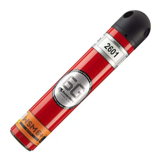
User Manual for the Type 8370 UM-8370 WSM 6+ Transponder Issue A Rev 1 Figure 3-1 Type 8370-1111 Omni-Directional Wideband WSM 6+ Figure 3-2 Type 8370-4112 Directional Wideband WSM 6+ Endcap The connector endcap shields the electrical charging socket and ON/OFF switch. When not in use, the unit should be switched OFF to preserve battery charge. -
Page 14: Connectors
3.5.1 Manufacturing Data The manufacturing data details all essential information about the equipment that will be required if it is necessary to contact Sonardyne International Limited. 3.5.2 Serial No. The serial no. is the unique WSM 6+ identification number and should be quoted in all communications with Sonardyne International Ltd and their agents. -
Page 15: Transducer Type
These can be changed by software, via the RS232 link. All Sonardyne wideband addresses are available as well as all HPR 400 channels. A full table of frequencies for each valid navigation channel is given in Appendix A – Frequency Tables. -
Page 16: Functionality
Issue A Rev 1 Functionality Sonardyne's WSM 6+ offers wideband navigation replies which are capable of significant improvements in ranging accuracy and repeatability, especially in responder mode. It also retains compatibility with existing HPR and LUSBL range-bearing acoustic navigation systems. The acoustic signal level transmitted by the Type 8370-4112 is strongest on axis and useful over a 90 degree cone. -
Page 17: Battery And Charger
The WSM 6+ is fitted with a 2000 mAh nickel metal hydride battery pack and must only be charged with the Sonardyne Type 8370-011-01 (/-02 ) comms/charger unit and matching charger PSU. Earlier types of transponder have different battery pack capacity, different rating AC power packs and different versions of charger are not compatible with the WSM 6+. -
Page 18: Deeply Discharged Battery
Note The battery pack must only be removed and replaced by qualified Sonardyne personnel. Charging a pack which has suffered deep discharge can result in some gas being discharged by the affected cells. If the pressure relief vent is found to be proud of its normal position, this may be an indication that one or more cells have gassed and the appropriate action should be taken to recover the battery pack as described above. -
Page 19: Pressure Relief Vent Valve
User Manual for the Type 8370 UM-8370 WSM 6+ Transponder Issue A Rev 1 3.9.5 Pressure Relief Vent Valve A Pressure Relief Vent Valve is provided to make sure there is no build-up of gas inside the transponder caused by the charging process. The battery manufacturer recommends the batteries are charged in an open environment. -
Page 20: Section 4 - Installation
User Manual for the Type 8370 UM-8370 WSM 6+ Transponder Issue A Rev 1 Section 4 – Installation Introduction Before installing the equipment, make sure Section 2 – Safety is read and fully understood. Pre-Use Checks Before installation, checks should be carried out to make sure the WSM 6+ is serviceable and ready for use. -
Page 21: Charging The Battery
User Manual for the Type 8370 UM-8370 WSM 6+ Transponder Issue A Rev 1 To operate the Pressure Relief Vent Valve: Note Refer to Warnings in Section 2 – Safety “Risk of toxic gases and corrosive liquids”. Screw an M4 bolt into the Pressure Relief Vent Valve. -
Page 22: Figure 4-2 Wsm 6+ Battery Charging Connections
User Manual for the Type 8370 UM-8370 WSM 6+ Transponder Issue A Rev 1 Figure 4-2 WSM 6+ Battery Charging Connections ON/OFF Switch PSU 2.1mm Power Socket WSM 6+Connector Comms/Charger Connector 8370-011 Comms/Charger PSU (AC Power Cable Not Shown) Section 4 – Installation... -
Page 23: Section 5 - Operation
WSM 6+ may not reply to interrogations or may reply erratically. In Sonardyne Wideband configuration, a single interrogation signal will trigger a wideband reply after the selected ‘turn-around time’. -
Page 24: 6G Terminal Lite
User Manual for the Type 8370 UM-8370 WSM 6+ Transponder Issue A Rev 1 5.3.1 6G Terminal Lite 6G Terminal Lite software is supplied on the 6G Utilities CD. Refer to UM-8300-099-User Manual for 6G Terminal Lite (referred to as 6G Terminal Lite in this manual). -
Page 25: Electrical Connections
User Manual for the Type 8370 UM-8370 WSM 6+ Transponder Issue A Rev 1 The WSM 6+ has a red plastic sleeve around the transponder to provide both electrical and some mechanical isolation. Units should be mounted with their body axis vertical. -
Page 26: After Use
User Manual for the Type 8370 UM-8370 WSM 6+ Transponder Issue A Rev 1 Table 5-1 WSM 6+ Pre-Deployment Checklist Type Number: 8370-000-…. Address: Serial Number: Firmware Version: Tested By: Date: Reference Test Tick / Comment Section 4.2.1 Checking the Pressure Relief Vent Valve Section 4.2.2... -
Page 27: Section 6 - Maintenance
Retrieval from the Water Refer to Section 9 – Retrieval and Storage”. Dismantling Dismantling of the WSM 6+ must only be carried out by Sonardyne qualified personnel. Inspection Inspect the WSM 6+ for the following: Inspect the Pressure Relief Vent Valve; refer to Section 4.2.1 “Checking the Pressure Relief Vent Valve”. -
Page 28: Corrosion Removal
User Manual for the Type 8370 UM-8370 WSM 6+ Transponder Issue A Rev 1 Corrosion Removal Cases of slight corrosion found on the transponder housing can be treated effectively as described below. Make sure the WSM 6+ is thoroughly clean and dry. -
Page 29: Section 7 - Functional Testing
User Manual for the Type 8370 UM-8370 WSM 6+ Transponder Issue A Rev 1 Section 7 – Functional Testing Introduction To ensure the WSM 6+ functions correctly, the following functional tests can be carried out: • Transponder test • Responder test •... -
Page 30: Functional Tests
User Manual for the Type 8370 UM-8370 WSM 6+ Transponder Issue A Rev 1 Functional Tests 7.4.1 Serial Communications Test Use the following procedure to test the serial communications of the WSM 6+. Using the 8370-011-01/02 charger/comms interface, connect the WSM 6+ to a PC. -
Page 31: Sensor Test
User Manual for the Type 8370 UM-8370 WSM 6+ Transponder Issue A Rev 1 On the Baud Rate combo box, Type 1200 and then click Connect. On the Manual Commands tab type @ in the text box and then click Send. The WSM 6+ should transmit an audible navigation pulse. -
Page 32: Test Report
User Manual for the Type 8370 UM-8370 WSM 6+ Transponder Issue A Rev 1 To update the firmware refer to 6G Terminal Lite, Section “Firmware Update”. 7.4.8 Test Report On completion of functional testing of the transponder a test report can be created. The report lists all information displayed on the 6G Setup tab of the 6G Terminal Lite software. -
Page 33: Section 8 - Fault Diagnosis
Operating at long range Increase power to the surface transceiver Ray-bending effects stopping the Use software application transponder from receiving RAY_TRACE available from Sonardyne Int Ltd. Surface thermocline refracting Lower transducer below reply signals thermocline Noise level at surface transducer Lower the dunking... -
Page 34: Transponder Replies To Commands, But Not To Interrogations
011-01/02 ) and the PSU being used has the correct rating ( 1.3 A 30 V ) NiMH battery has degraded Contact your nearest Sonardyne office to get the unit repaired. Section 8 – Fault Diagnosis... -
Page 35: Section 9 - Retrieval And Storage
User Manual for the Type 8370 UM-8370 WSM 6+ Transponder Issue A Rev 1 Section 9 – Retrieval and Storage Introduction Before retrieving the transponder, make sure Section 2 – Safety is read and fully understood. Retrieval On retrieval from the water, the following procedures must be carried out before the transponder is stored. -
Page 36: Table 9-1 Storage Conditions
User Manual for the Type 8370 UM-8370 WSM 6+ Transponder Issue A Rev 1 Table 9-1 Storage Conditions Item Specification -20 to 55°C (see Note below) Storage Temperature Relative Humidity 20 to 80% (non-condensing) Note To prolong the life of the NiMH batteries it is recommended not exceed the storage temperature range of -20 to 55°C. -
Page 37: Section 10 - Spares
User Manual for the Type 8370 UM-8370 WSM 6+ Transponder Issue A Rev 1 Section 10 – Spares 10.1 Introduction Table 10-1 shows all available WSM 6+ spares. Table 10-1 Component Identification Part No. Dwg No Description Lower Endcap CON U/W 5W dummy F/M micro Subconn MCDC5F 312-6874 –... -
Page 38: Section 11 - Technical Specifications
User Manual for the Type 8370 UM-8370 WSM 6+ Transponder Issue A Rev 1 Section 11 – Technical Specifications 11.1 Technical Drawings Figure 11-1 Type 8370-1111 Omni-Directional WSM 6+ Outline Drawing Figure 11-2 Type 8370-4112 Directional WSM 6+ Outline Drawing... -
Page 39: 11.2 Pin-Out Wiring Connections
User Manual for the Type 8370 UM-8370 WSM 6+ Transponder Issue A Rev 1 11.2 Pin-Out Wiring Connections 11.2.1 Standard Housing Wiring Connections Figure 11-3 5-Way Connector Pin Out and Mating Tail Bulkhead – Male Subconn MCBH5M Cable – Female Subconn MCIL5F... -
Page 40: 11.2.2 External Remote Release Option Wiring Connections
User Manual for the Type 8370 UM-8370 WSM 6+ Transponder Issue A Rev 1 11.2.2 External Remote Release Option Wiring Connections Figure 11-4 8-Way Connector Pin Out and Mating Tail Bulkhead – Female Subconn MCBH8F Cable – Male Subconn MCIL8M... -
Page 41: Specifications For Type 8370-1111 & 8370-4112 Wsm 6
17 days (8 ms @ 1/sec, NPL187 – WB2) 6 days (8 ms @ 1/sec, NPL175 – WB2) 19 days 3 hours using Sonardyne charger Type 8370-011-01 Charging time (temperature must be between 10 and 40ºC) Section 11 – Technical Specifications... - Page 42 User Manual for the Type 8370 UM-8370 WSM 6+ Transponder Issue A Rev 1 Parameter Specification External Power Voltage: 24 V dc nominal, 28 V dc maximum Current: Average 5 mA when transmitting 1 pulse/sec @ low External Power Requirement...
-
Page 43: Appendix A - Frequency Tables
24500 24000 27500 A.2 Sonardyne Wideband Frequency Table The acoustic command address set in the unit will determine the carrier frequency of the coded reply and the interrogation signal used in IIS tracking. The CIS setting will determine the carrier frequency of the common interrogate signal used for CIS tracking. - Page 44 User Manual for the Type 8370 UM-8370 WSM 6+ Transponder Issue A Rev 1 A.2.1 Wideband Address Frequency Chart Appendix A – Frequency Tables...
-
Page 45: Definitions
Individual Interrogate Signal. iWand The iWand is a hand held acoustic transponder test and configuration device developed for use with Sonardyne’s 6G instruments. Light Emitting Diode. Long Base Line Positioning A system where two or more transponders are on the seabed. The positions... - Page 46 T. +44 (0) 1252 872288 T. +55 22 2123 4950 T.+65 6542 1911 F. +44 (0) 1252 876100 F. +55 22 2123 4951 F. +65 6542 6937 sales@sonardyne.com brasil.sales@sonardyne.com asia.sales@sonardyne.com Houston, USA Aberdeen, UK 24/7 Emergency Helpline 8280 Willow Place Drive North Units 12–14,...
Need help?
Do you have a question about the um-8370 and is the answer not in the manual?
Questions and answers