SOYO Super 7 SY-5EMA+ User's Manual & Technical Reference
Pentium class cpu supported eteq82c663 pci/agp motherboard atx form factor
Hide thumbs
Also See for Super 7 SY-5EMA+:
- Quick start manual (27 pages) ,
- Quick start manual (17 pages) ,
- User's manual & technical reference (74 pages)
Table of Contents
Advertisement
Quick Links
Advertisement
Table of Contents

Related Manuals for SOYO Super 7 SY-5EMA+


Summary of Contents for SOYO Super 7 SY-5EMA+
- Page 1 All manuals and user guides at all-guides.com SY-5EMA+ V1.0 Super 7 Motherboard ************************************************ ® Pentium Class CPU supported ETEQ82C663 PCI/AGP Motherboard ATX Form Factor ************************************************ User's Guide & Technical Reference...
- Page 2 2000. The “SY-5EMA+: system is eligible to carry the NSTL :Year 2000 Certification” seal. The Year 2000 certification test has been done under the following system configuration: Company Name : SOYO COMPUTER INC. System Model Name : SY-5EMA+ Hardware Revision...
- Page 3 USB Mouse: WINIC/F4ZFDM-A50 PS/2 Keyboard: SILITED/GYUM99SK PS/2 Mouse: GENIUS/FSUGMZFC Modem: ACEEX/IF AXDM1414 This declaration is given for the manufacturer SOYO COMPUTER INC. No.21, Wu-Kung 5 Rd., Hsing Chuang City, Taipei Hsien, Taiwan, R.O.C. The test was carried out by SPORTON INTERNATIONAL INC.
- Page 4 It is the policy of Soyo Computer Inc. to respect the valid patent rights of third parties and not to infringe upon or assist others to infringe upon such rights.
-
Page 5: Table Of Contents
All manuals and user guides at all-guides.com Table of Contents SY-5EMA+ V1.0 Table of Contents SY-5EMA+ V1.0 MOTHERBOARD LAYOUT........1 CHAPTER 1 INTRODUCTION............2 KEY FEATURES ............2 HANDLING THE MOTHERBOARD ....... 5 ELECTROSTATIC DISCHARGE PRECAUTIONS..5 CHAPTER 2 HARDWARE SETUP ............ 6 PREPARATIONS ............6 UNPACKING THE MOTHERBOARD ......7 INSTALLATION GUIDE..........8... -
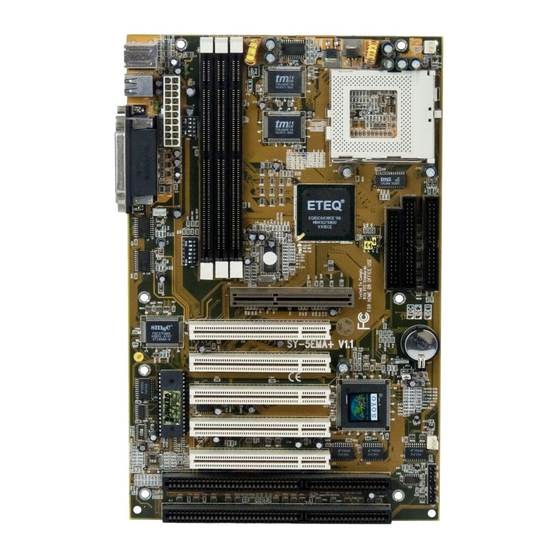
Page 6: Sy-5Ema+ V1.0 Motherboard Layout
All manuals and user guides at all-guides.com Introduction SY-5EMA+ V1.0 SY-5EMA+ V1.0 Motherboard Layout DIMM3 DIMM 2 DIMM 1 CPUFAN PS/2 Mouse PS/2 KB Connector Connector ATX Power P .B. SRAM USB1 USB2 64Kx64 P .B. SRAM 64Kx64 (Optional) ® TAG 32Kx8 JP44 IDE 2... -
Page 7: Chapter 1 Introduction
All manuals and user guides at all-guides.com Introduction SY-5EMA+ V1.0 Chapter 1 INTRODUCTION The SY-5EMA+ V1.0 AGP/PCI Motherboard is a high-performance ATX form-factor system board. SY-5EMA+ V1.0 uses the ® ETEQ82C663 PCI Chipset technology and supports Pentium class processors. This Motherboard is fully compatible with industry standards and adds many technical enhancements. - Page 8 All manuals and user guides at all-guides.com Introduction SY-5EMA+ V1.0 DRAM Controller Ø Supports 3 strips of 168-pin SDRAM unbeffured DIMM 3 x 168-pin DIMM banks support 8/16/32/64/128/256 MB unbuffered DIMM modules Ø Memory configuration: System memory: 8MB to 768MB with EDO/SDRAM SY-5EMA+ V1.0 PLATFORM FEATURES Board Size 4-layer PCB, 19x30.5cm(7.5”x12”), ATX Form Factor...
- Page 9 All manuals and user guides at all-guides.com Introduction SY-5EMA+ V1.0 5-pin Serial Infrared Device Connector Keylock 5-pin KeyLock Connector Reset 2-pin Reset Switch Connector Speaker 4-pin PC Speaker Connector TB_LED 2-pin Turbo LED Connector HDD_LED 2-pin IDE Device LED Connector PWRBT ATX Power On/Off Switch 2-pin Connector CMOS Clear Jumper...
-
Page 10: Handling The Motherboard
All manuals and user guides at all-guides.com Introduction SY-5EMA+ V1.0 1-2 HANDLING THE MOTHERBOARD To avoid damage to your Motherboard, follow these simple rules while unpacking: Ø Before handling the Motherboard, ground yourself by grasping an unpainted portion of the system's metal chassis. Ø... -
Page 11: Chapter 2 Hardware Setup
All manuals and user guides at all-guides.com Hardware Setup SY-5EMA+ V1.0 Chapter 2 HARDWARE SETUP Congratulations on your purchase of SY-5EMA+ V1.0 Super 7 Motherboard. You are about to install and connect your new Motherboard. Note: Do not unpack the Motherboard from its protective anti-static packaging until you have made the following preparations. -
Page 12: Unpacking The Motherboard
All manuals and user guides at all-guides.com Hardware Setup SY-5EMA+ V1.0 2-2 Unpacking the Motherboard When unpacking the Motherboard, check for the following items: Ø The SY-5EMA+ V1.0 ETEQ82C663 PCI/AGP Motherboard Ø This Quick Start Guide * Ø The Installation CD-ROM * Ø... -
Page 13: Installation Guide
All manuals and user guides at all-guides.com Hardware Setup SY-5EMA+ V1.0 2-3 Installation Guide We will now begin the installation of the Motherboard. Please follow the step-by-step procedure designed to lead you to a complete and correct installation. Step 1. CPU Installation ®... - Page 14 All manuals and user guides at all-guides.com Hardware Setup SY-5EMA+ V1.0 Follow these steps to install the CPU in the Socket 7: Lift the socket handle up to a vertical position. Align the blunt edge of the CPU with the matching pinhole distinctive edge on the socket.
- Page 15 All manuals and user guides at all-guides.com Hardware Setup SY-5EMA+ V1.0 Step 3. CPU Voltage Setting (SW2) ® CPU Voltage ® Please verify the correct voltage with your dealer before installation. Use the following tables to set SW2 to the proper "Voltage Value", according to the specifications marked on your CPU: This Motherboard comes with pre-configured setting of CPU voltage.
- Page 16 All manuals and user guides at all-guides.com Hardware Setup SY-5EMA+ V1.0 CPU you are installing and adjust the settings on SW2 accordingly. This motherboard supports CPU core voltages from 2.0 to 3.5V in 0.1V increments. Use the following tables to set the CPU voltage jumpers SW2 to match the voltage value of your CPU: CPU Core Voltage Setting: SW2 Voltage Value...
- Page 17 All manuals and user guides at all-guides.com Hardware Setup SY-5EMA+ V1.0 Voltage Settings for Various Processors Processor Voltage Value: SW2 Voltage Setting Single Voltage Intel P54C - P100 :3.3V Intel P54C - P133 :3.3V Single Voltage Intel P54C - P166 :3.5V Intel P54C - P200 :3.5V...
- Page 18 All manuals and user guides at all-guides.com Hardware Setup SY-5EMA+ V1.0 Voltage Settings for Various Processors (continued) Processor Voltage Value: SW2 Voltage Setting Cyrix 6x86(L) PR166+ The Cyrix 6x86(L) come in several Cyrix 6x86(L) PR200+ versions with different voltages. Please ask your dealer for the correct voltage.
- Page 19 All manuals and user guides at all-guides.com Hardware Setup SY-5EMA+ V1.0 Step 4. CPU Frequency Setting (SW1) ® Host Bus Frequency Frequency Multiplier ® The SY-5EMA+ V1.0 Motherboard is designed to support most ® Pentium class processors currently on the market. Jumpers SW1 is used to configure the Motherboard frequency parameters to match the working frequency of your CPU.
- Page 20 All manuals and user guides at all-guides.com Hardware Setup SY-5EMA+ V1.0 CPU FREQUENCY SETTING (SW1) Configure the SW1 jumpers to the settings that match your CPU speed. Refer to the following tables to set the Frequency Multiplier and Host Bus Frequency of your CPU: Frequency Multiplier Host Bus Frequency Host Bus...
- Page 21 All manuals and user guides at all-guides.com Hardware Setup SY-5EMA+ V1.0 Please refer to the following table that gives you the correct frequency settings for the specific brand and model of CPU you are installing on this Motherboard. ® Frequency Settings for Intel Processors Processor Frequency...
- Page 22 All manuals and user guides at all-guides.com Hardware Setup SY-5EMA+ V1.0 Frequency Settings for AMD ™ Processors Processor Frequency Ratio Frequency Setting Clock Clock Clock Setting: SW1 AMD K5 - PR100 1.5 x 66MHz 66MHz 33MHz 1 2 3 4 5 6 AMD K5 - PR133 2.0 x 66MHz 66MHz...
- Page 23 All manuals and user guides at all-guides.com Hardware Setup SY-5EMA+ V1.0 Frequency Settings for AMD ™ Processors (Continued) Processor Frequency Ratio Frequency Setting Clock Clock Clock Setting: SW1 AMD K6-2 350 3.5 x 100MHz 66MHz 33MHz 1 2 3 4 5 6 AMD K6-2 380 4.0 x 95MHz 63.4MHz 31.7MHz...
- Page 24 All manuals and user guides at all-guides.com Hardware Setup SY-5EMA+ V1.0 Frequency Settings for Cyrix ™ Processors (Continued) Processor Frequency Ratio Frequency Setting Clock Clock Clock Setting: SW1 Cyrix MX - PR200** 2.5 x 66MHz 66MHz 33MHz 1 2 3 4 5 6 Cyrix MX - PR200** 2.0 x 75MHz...
- Page 25 All manuals and user guides at all-guides.com Hardware Setup SY-5EMA+ V1.0 Frequency Settings for IDT ™ Processors Processor Frequency Ratio Frequency Setting Clock Clock Clock Setting: SW1 IDT X86 CPU C6/2-200 3.0 x 66MHz 66MHz 33MHz 1 2 3 4 5 6 IDT X86 CPU C6/2-225 3.0 x 75MHz 75MHz 37.5MHz 1 2 3 4 5 6...
- Page 26 All manuals and user guides at all-guides.com Hardware Setup SY-5EMA+ V1.0 Step 5. Set JP8,JP9,JP10 for SDRAM frequency JP8 is used to indicate the frequency of the CPU bus clock to the ETEQ chipset. JP9 and JP10 are used to determine that the SDRAM is running at the frequency of the CPU bus clock or the AGP clock.
- Page 27 All manuals and user guides at all-guides.com Hardware Setup SY-5EMA+ V1.0 Step 6. DRAM Module Installation This Motherboard supports three DIMM banks from 8 to 256 MB with no other restrictions on memory configurations. You can install the memory in any combination without having to rely on a memory configuration table.
- Page 28 All manuals and user guides at all-guides.com Hardware Setup SY-5EMA+ V1.0 MEMORY CONFIGURATION This Motherboard features 3 x DIMM Banks for 168-pin 3.3V unbuffered DIMM modules Your board comes with three DIMM sockets, providing support for up to 768MB of main memory using DIMM modules from 8MB to 256MB.
- Page 29 All manuals and user guides at all-guides.com Hardware Setup SY-5EMA+ V1.0 Step 9. Front Panel Connections ® HDD LED Speaker Turbo Keylock PWRBT Power ® Reset Plug the computer case's front panel devices to the corresponding connectors on the Motherboard. 1.
- Page 30 All manuals and user guides at all-guides.com Hardware Setup SY-5EMA+ V1.0 3. Speaker Attach the 4-pin PC speaker cable from the case to the Speaker connector on the Motherboard. 4. Turbo LED Connecting the 2-pin Turbo LED cable to the corresponding Turbo LED connector will cause the LED to light whenever the system is in Turbo mode.
- Page 31 All manuals and user guides at all-guides.com Hardware Setup SY-5EMA+ V1.0 Step 10. Back Panel Connections All external devices such as the keyboard, printer, PS/2 mouse, modem, USB, can be plugged directly onto the Motherboard back panel. Only after you have fixed and locked the Motherboard to the computer case can you start connecting the external peripheral devices.
- Page 32 All manuals and user guides at all-guides.com Hardware Setup SY-5EMA+ V1.0 1. Onboard Serial Port COM1,COM2 External peripherals that use serial transmission scheme include: serial mouse, and modem. Plug the serial device cables directly into the COM1or COM2 9-pin male connector located at the rear panel of the Motherboard. 2.
- Page 33 All manuals and user guides at all-guides.com Hardware Setup SY-5EMA+ V1.0 Wake-On-LAN (WOL) Attach the 3-pin connector from the LAN card which supports the Wake-On-LAN (WOL) function to the JP44 connector on the Motherboard. This WOL function lets users wake up the connected computer through the LAN card.
- Page 34 All manuals and user guides at all-guides.com Hardware Setup SY-5EMA+ V1.0 Step 11. CPU Cooling Fan Installation After you have seated the CPU cooling fan properly on the processor, attach the 3-pin fan cable to the CPUFAN connector on the Motherboard. To avoid damage to the system, install according to the following pin assignment: CPU Cooling Fan...
- Page 35 All manuals and user guides at all-guides.com Hardware Setup SY-5EMA+ V1.0 Step 13. ATX Power Supply Plug the connector from the power directly into the 20-pin male ATX PW connector on the Motherboard, as shown in the following figure. ® ATX Power ®...
- Page 36 All manuals and user guides at all-guides.com Hardware Setup SY-5EMA+ V1.0 Please install the ATX power according to the following pin assignment: ATX Power 3.3V 3.3V -12V 3.3V Ø Pay special care to the directionality. PS-ON PW-OK 5VSB Step 14. CMOS Clearing (JP5) After you have turned off your computer, clear the CMOS memory by momentarily shorting pins 2-3 on jumper JP5, for a few seconds.
- Page 37 All manuals and user guides at all-guides.com Hardware Setup SY-5EMA+ V1.0 Step 15. MULTI I/O ADDRESSES Default settings for multi-I/O addresses are as follows: Port I/O Address Status LPT1 378H ECP + EPP COM1 3F8H COM2 2F8H Warning: If a default I/O address conflicts with other I/O cards such as sound card, you must change one of the I/O addresses to remedy to this address conflict.
- Page 38 All manuals and user guides at all-guides.com Hardware Setup SY-5EMA+ V1.0 Step 16. Power On You have now completed the hardware installation of your Motherboard successfully. 1. Turn the power on 2. To enter the BIOS Setup Utility, press the <DEL> key while the system is performing the diagnostic checks, Note: If you have failed to enter the BIOS, wait until the boot up sequence is completed.
-
Page 39: Chapter 3 Bios Setup Utility
All manuals and user guides at all-guides.com BIOS Setup Utility SY-5EMA+ V1.0 Chapter 3 BIOS SETUP UTILITY This Motherboard's BIOS setup program uses the ROM PCI/ISA BIOS program from Award Software Inc. To enter the Award BIOS program's Main Menu: 1. - Page 40 All manuals and user guides at all-guides.com BIOS Setup Utility SY-5EMA+ V1.0 Hot Keys: Function keys give you access to a group of commands throughout the BIOS utility. Function Command Description Help Gives the list of options available for each item. Color Change the color of the display window.
-
Page 41: Standard Cmos Setup
All manuals and user guides at all-guides.com BIOS Setup Utility SY-5EMA+ V1.0 3-1 STANDARD CMOS SETUP Select the [STANDARD CMOS SETUP] option from the Main Menu and press [Enter] key. ROM PCI/ISA BIOS STANDARD CMOS SETUP AWARD SOFTWARE, INC. Date (mm:dd:yy) : Fri, May 29 1998 Time (hh:mm:ss) : 9 : 42 : 43... - Page 42 All manuals and user guides at all-guides.com BIOS Setup Utility SY-5EMA+ V1.0 3-1.2 Hard Disks Type & Mode Choose the type and mode for the hard disks that you have already installed. Primary Setting Description Note (Secondary) Master & Slave Type Auto BIOS detects hard disk type...
- Page 43 All manuals and user guides at all-guides.com BIOS Setup Utility SY-5EMA+ V1.0 3-1.4 Video Select the video mode: EGA/VGA (Default), CGA 40, CGA 80, Mono (Monochrome). 3-1.5 Halt On When the BIOS detects system errors, this function will stop the system.
-
Page 44: Bios Features Setup
All manuals and user guides at all-guides.com BIOS Setup Utility SY-5EMA+ V1.0 3-2 BIOS FEATURES SETUP Select the [BIOS FEATURES SETUP] option from the Main Menu and press [Enter] key. ROM PCI/ISA BIOS BIOS FEATURES SETUP AWARD SOFTWARE, INC. Virus Warning : Disabled Video BIOS Shadow... - Page 45 All manuals and user guides at all-guides.com BIOS Setup Utility SY-5EMA+ V1.0 3-2.1 Virus Warning Setting Description Note Virus Warning Disabled Default Enabled Enable this option to protect the boot sectors and partition tables of your hard disk. Any attempt to write to them will the system to halt and display a warning message.
- Page 46 All manuals and user guides at all-guides.com BIOS Setup Utility SY-5EMA+ V1.0 3-2.3 System Boot Control Settings System Boot Setting Description Note Control Settings Quick Power On Disabled Self Test Enabled Provides a fast POTS at Default boot-up. Boot Sequence A, C, SCSI Choose the boot sequence adapted to...
- Page 47 All manuals and user guides at all-guides.com BIOS Setup Utility SY-5EMA+ V1.0 System Boot Control Settings (continued) System Boot Setting Description Note Control Settings Gate A20 Option Normal Fast Allows RAM access Default above 1MB using the fast gate A20 line. Memory Parity Enabled This allows to perform a...
- Page 48 All manuals and user guides at all-guides.com BIOS Setup Utility SY-5EMA+ V1.0 3-2.5 Other Control Options Other Control Setting Description Note Options Security Setup Use this feature to prevent Default Option Unauthorized system boot-up or use of BIOS Setup. “Setup”, If a password is set, the password prompt only appears if you attempt to enter the Setup program.
- Page 49 All manuals and user guides at all-guides.com BIOS Setup Utility SY-5EMA+ V1.0 Other Control Options (Continued) Other Control Setting Description Note Options Video or Disabled Adapter BIOS Enabled Default Shadow The BIOS is shadowed in a 16K segment if it is enabled and if it has BIOS present. These 16 segments can be shadowed from ROM to RAM.
-
Page 50: Chipset Features Setup
All manuals and user guides at all-guides.com BIOS Setup Utility SY-5EMA+ V1.0 3-3 CHIPSET FEATURES SETUP Caution: Change these settings only if you are already familiar with the Chipset. The [CHIPSET FEATURES SETUP] option changes the values of the chipset registers. These registers control the system options in the computer. - Page 51 All manuals and user guides at all-guides.com BIOS Setup Utility SY-5EMA+ V1.0 CHIPSET FEATURES SETUP CHIPSET Setting Description Note FEATURES DIMM 1 DRAM FP/EDO Use the default setting Default Timing 70ns DIMM 2 DRAM Normal Choose DRAM Timing. Timing Medium DIMM 3 DRAM Fast, Timing...
- Page 52 All manuals and user guides at all-guides.com BIOS Setup Utility SY-5EMA+ V1.0 CHIPSET FEATURES SETUP (Continued) CHIPSET Setting Description Note FEATURES AGP Aperture AGP could use the DRAM Default Size 4-256M as its video RAM. Choose the JDRAM size that you wish to allocate as video RAM.
-
Page 53: Power Management Setup
All manuals and user guides at all-guides.com BIOS Setup Utility SY-5EMA+ V1.0 3-4 POWER MANAGEMENT SETUP The [POWER MANAGEMENT SETUP] sets the system's power saving functions. ROM PCI/ISA BIOS POWER MANAGEMENT SETUP AWARD SOFTWARE, INC. Primary INTR : ON ACPI function : Disabled IRQ3 (COM2) : Primary... - Page 54 All manuals and user guides at all-guides.com BIOS Setup Utility SY-5EMA+ V1.0 3-4.1 Power Management Controls Power Setting Description Note Management Controls ACPI Disabled Default function Enabled Enabled if you use Windows 98 and want to use ACPI Power User Define Lets you define the HDD and Management system power down times.
- Page 55 All manuals and user guides at all-guides.com BIOS Setup Utility SY-5EMA+ V1.0 3-4.2 PM Timers PM Timers Setting Description Note HDD Power Disable Default Down Some older 1-15Min When the set time has model HDDs elapsed, BIOS sends a may not support command to the HDD to this advanced power down.
- Page 56 All manuals and user guides at all-guides.com BIOS Setup Utility SY-5EMA+ V1.0 3-4.3 PM Events PM Events Setting Description Note Enabled the power managemnet. Default LPT & COM LPT/COM Enabled the power Default management timer. NONE HDD & FDD Enabled the power Default management timers when the event is detected on the Hard...
- Page 57 All manuals and user guides at all-guides.com BIOS Setup Utility SY-5EMA+ V1.0 PM Events (Continued) PM Events Setting Description Note IRQ# Primary IRQ3(COM2), IRQ4(COM1), IRQ5(LPT2), IRQ6(Floppy Disk), IRQ7(LPT1), IRQ12(PS/2 mouse), IRQ13(Coprocessor), IRQ14(HardDsik) Secondary IRQ9(IRQ2 Redir), IRQ10( Reserved), IRQ11(Reserved) Disabled IRQ8 (RTC Alarm), IRQ15 (Reserved)
-
Page 58: Pnp/Pci Configuration Setup
All manuals and user guides at all-guides.com BIOS Setup Utility SY-5EMA+ V1.0 3-5 PNP/PCI CONFIGURATION SETUP This option sets the Motherboard's PCI Slots. ROM PCI/ISA BIOS PNP/PCI CONFIGURATION SETUP AWARD SOFTWARE, INC. : No CPU to PCI Write Buffer : Enabled PNP OS Installed : Manual PCI Master Broken Timer... - Page 59 All manuals and user guides at all-guides.com BIOS Setup Utility SY-5EMA+ V1.0 3-5.1 PNP/PCI Configuration Controls PNP/PCI Setting Description Note Controls PNP OS Use the default setting Disabled Installed Resources Manual BIOS does not manage PCI/ISA Controlled By PnP card IRQ assignment. Requires to assign IRQ-# and DMA-# to PCI or ISA PnP manually.
- Page 60 All manuals and user guides at all-guides.com BIOS Setup Utility SY-5EMA+ V1.0 3-5.2 PNP/PCI Configuration Setup PNP/PCI Setting Description Note Setup If [Resources Controlled By] is set to [Manual] IRQ-# and PCI/ISA PnP Choose IRQ-# and IRQ-3,4,5,7,9,10, 11,12,14,15 DMA-# DMA-# assigned to DMA-0,1,3,5,6,7 assigned to: PCI/ISA PnP card.
-
Page 61: Load Setup Defaults
All manuals and user guides at all-guides.com BIOS Setup Utility SY-5EMA+ V1.0 3-6 LOAD SETUP DEFAULTS Select the [LOAD SETUP DEFAULTS] option from the Main Menu to load the system values you have previously saved. This option is recommended if you need to reset the system setup and to retrieve the old values. -
Page 62: Integrated Peripherals
All manuals and user guides at all-guides.com BIOS Setup Utility SY-5EMA+ V1.0 3-8 INTEGRATED PERIPHERALS Caution: Change these settings only if you are already familiar with the Chipset. The [INTEGRATED PERIPHERALS] option changes the values of the chipset registers. These registers control the system options in the computer. - Page 63 All manuals and user guides at all-guides.com BIOS Setup Utility SY-5EMA+ V1.0 3-8.1 IDE Device Controls IDE Controls Setting Description Note Onchip IDE Primary Disabled Use the On-board IDE Channel Channel Enabled Default Onchip IDE Second Disabled Turn off the On-board Channel IDE Channel Enabled...
- Page 64 All manuals and user guides at all-guides.com BIOS Setup Utility SY-5EMA+ V1.0 3-8.2 FDC Controls FDC Controls Setting Description Note Onboard FDC Disabled Turn off the on-board controller floppy controller Enabled Use the on-board Default floppy controller 3-8.3 Onboard Serial Ports Onboard Serial Setting Description...
- Page 65 All manuals and user guides at all-guides.com BIOS Setup Utility SY-5EMA+ V1.0 3-8.4 Onboard Parallel Ports IR Pins Controls Setting Description Note IR Duplex mode Half Select the IR mode Default your IR module Full supports Use IR Pins IR-RX2TX2 Default IR-RX TX 3-8.5 Onboard Parallel Ports...
-
Page 66: Supervisor Password
All manuals and user guides at all-guides.com BIOS Setup Utility SY-5EMA+ V1.0 3-9 SUPERVISOR PASSWORD Based on the setting you have made in the [Security Option] of the [BIOS FEATURES SETUP] section, the password prevents access to the system or the setup program by unauthorized users. Follow this procedure to set a new password or disable the password: Choose [BIOS FEATURES SETUP] in the Main Menu and press [Enter]. -
Page 67: User Password
All manuals and user guides at all-guides.com BIOS Setup Utility SY-5EMA+ V1.0 Enter your new password and press [Enter]. The following message appears, prompting to confirm the new password: Confirm Password: Re-enter your password and then press [Enter] to exit to the Main Menu. -
Page 68: Ide Hdd Auto Detection
All manuals and user guides at all-guides.com BIOS Setup Utility SY-5EMA+ V1.0 3-11 IDE HDD AUTO DETECTION This Main Menu function automatically detects the hard disk type and configures the STANDARD CMOS SETUP accordingly. ROM PCI/ISA BIOS CMOS SETUP UTILITY AWARD SOFTWARE, INC. -
Page 69: Chapter 4 Drivers Installation
HTML format with information on SOYO Motherboards and other products. Step 1. Insert the SOYO CD into the CD-ROM drive The SOYO CD will auto-run, and the SOYO CD Start Up Menu will display as shown below. (SOYO CD Start Up Program Menu) The SOYO CD Start Up Program automatically detects which SOYO Motherboard you own and displays the corresponding model name. - Page 70 After installation of windows, you will need to install the VIA drivers. Follow the instruction below. Click the Enter SOYO CD button to display the list of drivers that can be installed on your Motherboard. The start-up program displays the drivers available for the 5EMA+ V1.0 and the Windows...
- Page 71 Please select the driver you want to install and click OK, You will have to restart your system after installation. Only the drivers that are relevant to your board are displayed initially. ETEQ 4in1 driver package SOYO Speedpro BusMaster Driver for win 95/98 SOYO CD Xpress utility Display all drivers Cancel...
- Page 72 Install the drivers in sequence, starting with the FIRST driver. If you want to see all the drivers available on the SOYO –CD, click the Display all drivers on the SOYO CD button. Do NOT install drivers that are not suitable for your board, otherwise your system...
- Page 73 SOYO-CD and install the next driver. Note: Once you have selected a driver, the system will automatically exit the SOYO CD to begin the driver installation program. When the installation is complete, most drivers require to restart your system...
- Page 74 All manuals and user guides at all-guides.com Drivers Installation SY-5EMA+ V1.0...
Need help?
Do you have a question about the Super 7 SY-5EMA+ and is the answer not in the manual?
Questions and answers