Sign In
Upload
Manuals
Brands
Carrier Manuals
Refrigerator
69NT40-551-500
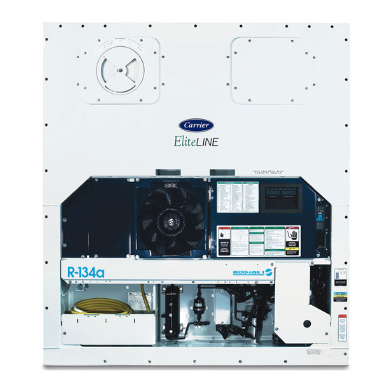
Carrier 69NT40-551-500 Manuals
Manuals and User Guides for Carrier 69NT40-551-500. We have
1
Carrier 69NT40-551-500 manual available for free PDF download: Operation And Service
Carrier 69NT40-551-500 Operation And Service (121 pages)
Container Refrigeration
Brand:
Carrier
| Category:
Refrigerator
| Size: 2.41 MB
Table of Contents
Table of Contents
4
Figure 2--1 Refrigeration Unit - Front Section
15
Evaporator Section
16
Figure 2--2 Evaporator Section
16
Compressor Section
17
Figure 2--3 Compressor Section
17
Air-Cooled Condenser Section
18
Figure 2--4 Air-Cooled Condenser Section
18
Water-Cooled Condenser Section
19
Figure 2--5 Water-Cooled Condenser Section
19
Control Box Section
20
Communications Interface Module
20
Figure 2--6 Control Box Section
20
Refrigeration System Data
21
Electrical Data
22
Safety and Protective Devices
23
Table 2--1 Safety and Protective Devices
24
Refrigeration Circuit
25
Standard Operation
25
Economized Operation
25
Unloaded Operation
25
Liquid Injection Operation
25
Expansion Bypass Solenoid Valve
25
Figure 2--7 Refrigeration Circuit Schematic - Standard Operation
26
Figure 2--8 Refrigeration Circuit Schematic - Economized Operation
27
Figure 2--9 Refrigeration Circuit Schematic - Unloaded Operation
27
Microprocessor
28
Temperature Control Microprocessor System
28
Figure 3--1 Temperature Control System
28
Key Pad
29
Display Module
29
Figure 3--2 Key Pad
29
Table 3--1 Key Pad Function
29
Controller
30
Controller Software
30
Configuration Software (Variables)
30
Operational Software (Function Codes)
30
Figure 3--3 Display Module
30
Modes of Operation
31
Temperature Control - Perishable Mode
31
Evaporator Fan Operation
31
Defrost Interval
31
Failure Action
31
Generator Protection
31
Compressor High Temperature, Low Pressure Protection
31
Perishable Mode - Conventional
31
Figure 3--4 Control Module
31
Perishable Mode - Economy
32
Perishable Mode - Dehumidification
32
Perishable, Dehumidification - Bulb Mode
32
Perishable - System Pressure Regulation
33
Temperature Control - Frozen Mode
33
Frozen Mode - Conventional
33
Frozen Mode - Economy
33
Condenser Fan Switch Override
33
Controller Alarms
33
Datacorder
35
Description
35
Datacorder Software
35
Sensor Configuration (Dcf02)
35
Logging Interval (Dcf03)
36
Thermistor Format (Dcf04)
36
Table 3--2 Datacorder Configuration Variables
36
Figure 3--5 Standard Configuration Download Report
37
Sampling Type (Dcf05 & Dcf06)
38
Alarm Configuration (Dcf07 - Dcf10)
38
Datacorder Power-Up
38
Pre-Trip Data Recording
38
Datacorder Communications
38
Table 3--3 Datacorder Standard Configurations
38
USDA Cold Treatment
39
USDA Cold Treatment Procedure
39
Figure 3--6 Data Reader
39
Datacorder Alarms
40
ISO Trip Header
40
Table 3--4 Controller Configuration Variables
41
Table 3--5 Controller Function Codes
43
Table 3--6 Controller Alarm Indications
47
Table 3--7 Controller Pre-Trip Test Codes
51
Table 3--8 Datacorder Function Code Assignments
55
Table 3--9 Datacorder Pre-Trip Result Records
56
Table 3--10 Datacorder Alarm Indications
57
Operation
58
INSPECTION (before Starting)
58
Connect Power
58
Connection to 380/460 VAC Power
58
Connection to 190/230 VAC Power
58
Adjust Fresh Air Makeup Vent
58
Figure 4--1 Autotransformer
58
Upper Fresh Air Makeup Vent
59
Lower Fresh Air Makeup Vent
59
Fresh Air Position Sensor
59
Figure 4--2 Make up Air Flow Chart
59
Connect Water-Cooled Condenser
60
Water-Cooled Condenser with Water Pressure Switch
60
Water-Cooled Condenser with Condenser Fan Switch
60
Connect Remote Monitoringreceptacle
60
Starting and Stopping Instructions
60
Starting the Unit
60
Stopping the Unit
60
Start-Up Inspection
60
Physical Inspection
60
Check Controller Function Codes
60
Complete Inspection
61
Pre-Trip Diagnosis
61
Observe Unit Operation
62
Probe Check
62
Sequence of Operation
62
Sequence of Operation - Compressor Phase Sequence
62
Figure 4--3 Controller Operation - Perishable Mode
63
Figure 4--4 Controller Operation - Frozen Mode
63
Sequence of Operation - Perishable Mode Cooling
64
Sequence of Operation - Perishable Mode Heating
64
Figure 4--5 Perishable Mode - Cooling
64
Figure 4--6 Perishable Mode Heating
64
Sequence of Operation - Frozen Mode Cooling
65
Sequence of Operation - Defrost
65
Figure 4--7 Frozen Mode
65
Emergency Bypass Operation
66
Troubleshooting
67
Unit will Not Start or Starts then Stops
67
Unit Operates Long or Continuously in Cooling
67
Unit Runs but Has Insufficient Cooling
68
Unit will Not Heat or Has Insufficient Heating
68
Unit will Not Terminate Heating
68
Unit will Not Defrost Properly
68
Abnormal Pressures (Cooling)
69
Abnormal Noise or Vibrations
69
Controller Malfunction
70
Evaporator Air Flow or Restricted Air Flow
70
Thermostatic Expansion Valve Malfunction
70
Autotransformer Malfunction
70
Water-Cooled Condenser or Water Pressure Switch
70
Compressor Operating in Reverse
71
Abnormal Temperatures
71
Abnormal Currents
71
Service
72
Section Layout
72
Manifold Gauge Set
72
Figure 6--1 Manifold Gauge Set
72
Figure 6--2 R-134A Manifold Gauge/Hose Set
72
REFRIGERATION SYSTEM SERVICE-UNITS with STANDARD PIPING (with Service Valves)
73
Service Connections
73
Pumping down the Unit
73
Figure 6--3 Service Valve
73
Refrigerant Leak Checking
74
Evacuation and Dehydration
74
Figure 6--4 Refrigeration System Service Connections
74
Refrigerant Charge
75
Adding Refrigerant to System (Full Charge)
75
Adding Refrigerant to System (Partial Charge)
75
Figure 6--5 Semi-Hermetic Piping Refrigeration System Service Connections
76
Compressor
78
Removal and Replacement of Compressor
78
Figure 6--6 Compressor Upper Mounting
78
Table 6--1 Compressor Kit
78
Figure 6--7 Compressor Lower Mounting
79
Compressor Oil Level
80
High Pressure Switch
80
Replacing High Pressure Switch
80
Checking High Pressure Switch
80
Figure 6--8 High Pressure Switch Testing
80
Condenser Coil
81
Condenser Fan and Motor Assembly
81
Water--Cooled Condenser Cleaning
81
Figure 6--9 Water-Cooled Condenser Cleaning - Forced Circulation
82
Filter Drier
83
Expansion Valves
83
Checking Superheat
83
Figure 6--10 Water-Cooled Condenser Cleaning - Gravity Circulation
83
Figure 6--11 Thermostatic Expansion Valve Bulb
83
Valve Replacement
84
Evaporator Coil Replacement
84
Figure 6--12 Evaporator Expansion Valve
84
Figure 6--13 Economizer Expansion Valves
84
Evaporator Heater Replacement
85
Economizer, Unloader, Liquid Injection, and Expansion Bypass Solenoid Valves
85
Figure 6--14 Hermetic Thermostatic Expansion Valve Brazing Procedure
85
Evaporator Fan and Motor Assembly
86
Replacing the Evaporator Fan Assembly
86
Disassemble the Evaporator Fan Assembly
86
Figure 6--16 Unloader Solenoid Valve
86
Figure 6--17 Evaporator Fan Assembly
86
Assemble the Evaporator Fan Assembly
87
Evaporator Fan Motor Capacitors
87
When to Check for a Defective Capacitor
87
Removing the Capacitor
87
Valve Override Controls
87
Table 6--2 Valve Override Control Displays
88
Suction Modulation Valve
89
Precheck Procedure
89
Checking the Stepper Valve
89
Autotransformer
89
Figure 6--18 Suction Modulation Valve (SMV)
89
Controller
90
Handling Modules
90
Controller Trouble-Shooting
90
Figure 6--19 Controller Section of the Control Box
90
Controller Programming Procedure
91
Removing and Installing a Module
91
Vent Position Sensor Service
92
Temperature Sensor Service
92
Sensor Checkout Procedure
92
Sensor Replacement
93
Sensor Re-Installation
93
Figure 6--20 Sensor Types
93
Figure 6--21 Sensor and Cable Splice
93
Table 6--3 Sensor Temperature/Resistance Chart
93
Figure 6--22 Supply Sensor Positioning
94
Figure 6--23 Return Sensor Positioning
94
Figure 6--24 Electronic Partlow Temperature Recorder
96
Maintenance of Painted Surfaces
97
Composite Control Box Repairs
97
Introduction
97
Cracks
97
Inserts
97
Door Hinge Inserts
97
Figure 6--25 Door Hinge Repair
98
Table 6--4 Crack, Chip & Hole Repair Kit
98
Table 6--5 Insert Repair Kit
98
Table 6--6 Drill Information
98
Figure 6--26 Insert Location
99
Communications Interface Module Installation
100
Figure 6--27 Communications Interface Installation
100
Table 6--7 Recommended Bolt Torque Values
100
Table 6--8 R-134A Temperature - Pressure Chart
101
Electrical Wiring Schematics
102
Introduction
102
Figure 7--2 SCHEMATIC DIAGRAM - Single Phase, Normal Evaporator Fan Capability
104
Figure 7--3 SCHEMATIC DIAGRAM - Single Phase, Single Evaporator Fan Capability
105
Figure 7--4 LEGEND -- Three--Phase Evaporator Fan Motor
106
Figure 7--5 SCHEMATIC DIAGRAM - Three--Phase Evaporator Fan Motor
107
Figure 7--6 SCHEMATIC DIAGRAM-Transfresh and Emergency Bypass
108
Figure 7--7 SCHEMATIC and WIRING DIAGRAM - Electronic Partlow Recorder
109
Figure 7--8 SCHEMATIC and WIRING DIAGRAM - Upper and Lower Vent Position Sensors
110
Figure 7--9 WIRING DIAGRAM - Single Phase, Normal Evaporator Fan Capability
111
Figure 7--10 WIRING DIAGRAM - Normal Evaporator Fan Capability with Bypass Module
113
Figure 7--11 WIRING DIAGRAM - Single Phase, Single Evaporator Fan Capability
115
Figure 7--12 WIRING DIAGRAM - Three--Phase Evaporator Fan Motor
117
Advertisement
Advertisement
Related Products
Carrier 69NT40-551-599
Carrier 69NT40-551-001
Carrier 69NT40-551-199
Carrier 69NT40-511-199
Carrier 69NT40--541--200 TO 299
Carrier 69NT40-541-508
Carrier 69NT40-511-359
Carrier 69NT40-511-300
Carrier 69NT40-541-505
Carrier 69NT40--541-2 Series
Carrier Categories
Air Conditioner
Heat Pump
Furnace
Thermostat
Chiller
More Carrier Manuals
Login
Sign In
OR
Sign in with Facebook
Sign in with Google
Upload manual
Upload from disk
Upload from URL