Advertisement
Quick Links
Cautions and Warnings
Overview
In This Publication
ã
2000 Simplex Time Recorder Co., Westminster, MA 01441-0001 USA
All specifications and other information shown were current as of publication, and are subject to change without notice.
DO NOT INSTALL ANY SIMPLEX PRODUCT THAT APPEARS
DAMAGED. Upon unpacking your Simplex product, inspect the contents of the
carton for shipping damage. If damage is apparent, immediately file a claim
with the carrier and notify Simplex.
ELECTRICAL HAZARD - Disconnect electrical power when making any
internal adjustments or repairs. Servicing should be performed by qualified
Simplex Representatives.
STATIC HAZARD - Static electricity can damage components. Therefore,
handle as follows:
1.
Ground yourself before opening or installing components (use the 553-484
Static Control Kit).
2.
Keep uninstalled component wrapped in anti-static material at all times.
RADIO FREQUENCY ENERGY - This equipment has been tested and found
to comply with the limits for a Class B digital device, pursuant to Part 15 of the
FCC rules. These limits are designed to provide reasonable protection against
harmful interference when the equipment is operated in a commercial
environment. This equipment generates, uses, and can radiate radio frequency
energy and, if not installed and used in accordance with the instruction manual,
may cause harmful interference to radio communications. Operation of this
equipment in a residential area may cause interference in which case the user
will be required to correct the interference at his own expense.
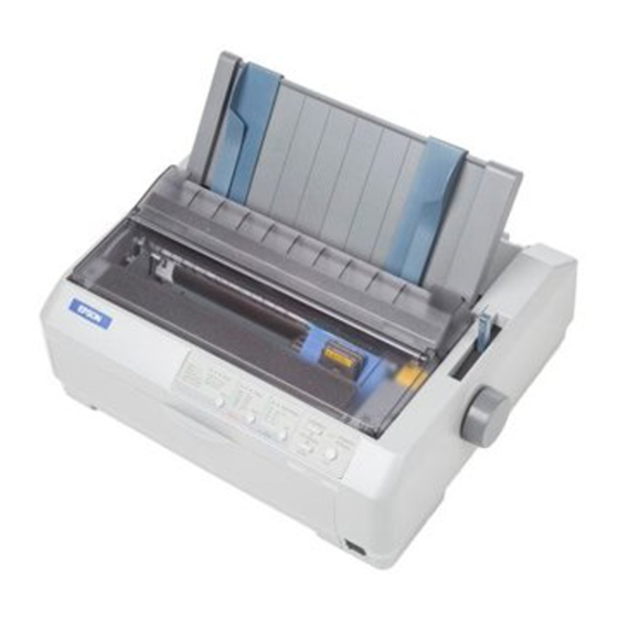
This document describes the installation procedure for the 4190-9013 Remote
Printer. Consult the User's Guide supplied with your printer for a detailed
description of mechanical setup, features and operating principles.
The 4190-9013 Remote Printer interfaces with Simplex Fire Alarm and Nurse
Call systems. The printer provides hard copy of status reports for these systems:
•
Fire Alarm
-
2120 Multiplex
-
4010
-
4020
-
4100+
•
5001 Nurse Call
The following topics are covered in this publication.
Topic
Your Printer's Default Settings
Serial Interface DIP Switches
Printer Connections
Connecting to Fire Alarm Systems
4010 Front Panel Programming for an RS-232 Port
Connecting to 5001 Nurse Call
Control Panel Buttons and Lights
firealarmresources.com
4190-9013 Remote Printer
Installation Instructions
-
4120 Network
-
4120 GCC
-
4120 NPU
Page Number
2
5
7
8
10
13
14
579-233
Rev. A
Advertisement

Related Manuals for Simplex 4190-9013


Summary of Contents for Simplex 4190-9013
- Page 1 Printer. Consult the User’s Guide supplied with your printer for a detailed description of mechanical setup, features and operating principles. The 4190-9013 Remote Printer interfaces with Simplex Fire Alarm and Nurse Call systems. The printer provides hard copy of status reports for these systems: •...
- Page 2 Your Printer's Default Settings Overview While you can often set the default settings through your application software or printer driver, you may need to change a default setting from the printer's control panel using the default setting mode. Table 1 below lists the default settings (in bold) and options you can select in this mode.
- Page 3 Your Printer's Default Settings, Continued Changing Default Settings Follow the steps below to enter the default setting mode and change the printer's default settings. Note: To print the language selection and default setting mode instructions, you need 5 sheets of letter- or A4-size single-sheet paper or 5 pages of continuous paper.
- Page 4 Serial Interface DIP Switches Introduction The serial interface card enables communication between the 4190-9013 Remote Printer and a host computer (see Figure 2 for the location of the serial interface compartment). The serial interface card has two sets of DIP switches (see Figure 1). You control interface operations by adjusting the switch settings.
- Page 5 Serial Interface DIP Switches, Continued Serial Interface Table 2 defines the serial interface settings for DIP Switch 1. DIP Switch 1 Table 2. DIP Switch 1 Settings Simplex Function Setting Interface Card Enable Disable Enable/Disable Word Length 8-bit 7-bit For both even...
- Page 6 Serial Interface DIP Switches, Continued Serial Interface Card Table 3 defines the settings for DIP Switch 2. DIP Switch 2 Table 3. DIP Switch 2 Settings Simplex Function Setting for both 1200 baud (2120, 4020, 4100+, Baud Rate 3 4120), and 9600...
-
Page 7: Printer Connections
Printer Connections Overview The following sections illustrate the connections between the 4190-9013 Remote Printer and the various host systems (Fire Alarm or Nurse Call) with which it is compatible. Connector Ports Use the port on the serial interface card for connections between the printer and host systems. - Page 8 Connecting to Fire Alarm Systems Connecting to 4020, 4100+, Use the 733-937 harness provided with the Simplex shipment (see Figure 3). 4120 Network, 4120 GCC or The harness is equipped with an RS-232 connector with internal suppression. 4120 NPU Systems Follow Steps 1 through 3 when using the serial interface port to connect to the host system.
- Page 9 Connecting to Fire Alarm Systems, Continued Connecting to 2120 Multiplex Use the 733-937 harness provided with the Simplex shipment (see Figure 2). System and 4010 FACP The harness is equipped with an RS-232 connector with internal suppression. Follow these steps to connect the printer to the 2120 Multiplex or 4010 FACP.
- Page 10 4010 Front Panel Programming for an RS-232 Port Introduction This section describes programming a printer port on a 4010 RS-232 card from the front panel of the 4010 FACP. Note: Login to the system at access level 4 before attempting to program the port.
- Page 11 4010 Front Panel Programming for an RS-232 Port, Continued Configuring RS-232 Port Press <NEXT> or <PREVIOUS> until <CONFIGURE CARDS> is Settings (continued) displayed and then press <ENTER>. Press <NEXT> or <PREVIOUS> until <MODIFY 4010 CARD> is displayed and then press <ENTER>. Press <NEXT>...
- Page 12 4010 Front Panel Programming for an RS-232 Port, Continued Configuring RS-232 Port 12. Choose which events are sent to the printer when they occur, as follows: Settings (continued) Send All Events to Printer. Press <ENTER> to send all of the events listed in Table 5 (below) to the printer.
- Page 13 Connect the female DB25 connector to the serial port of the 5001 CPU. Note: The 733-937 harness is not used when connecting to the 5001 Nurse Call system. Figure 7 illustrates the connection between the 4190-9013 printer and the 5001 CPU. 5001 CPU (DB25 SERIAL PRINTER PORT) SHIELD...
-
Page 14: Control Panel Buttons And Lights
Control Panel Buttons and Lights Control Panel Figure 8 illustrates the front panel of the printer. Refer to the indicator lights on the control panel for current status of the printer. Use the buttons to control printer settings. Figure 8. Control Panel Buttons and Lights Font button - Selects the font. - Page 15 Control Panel Buttons and Lights, Continued Control Panel, continued LF/FF button • Feeds paper line by line when pressed quickly. • Ejects a single sheet or advances continuous paper to the next top-of-form position when held down. Load/Eject button • Loads a single sheet of paper.
- Page 16 579-233 Rev. A firealarmresources.com...
Need help?
Do you have a question about the 4190-9013 and is the answer not in the manual?
Questions and answers