Table of Contents
Advertisement
Quick Links
Installation Guide
Power Monitoring
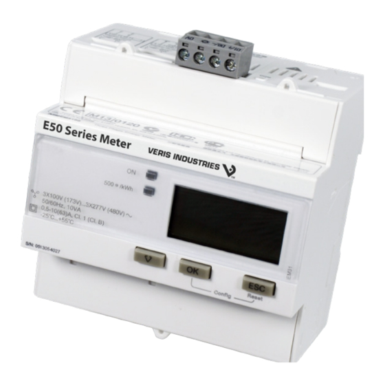
Product Overview
The E54C3C energy meter works on a on a single-phase, three-phase, or three-phase + neutral network with
partial metering and reset functions. The meter requires 1 Amp or 5 Amp current transformers. Data values are
instantly accessible using either the local display or the communications network. The E54C3C is equipped with
Modbus communication via RS-485. It provides four-quadrant energy measurements with one configurable
E54C3C
digital input, one configurable digital output, and up to four tariffs.
Important: COM.Protection is a mode that prevents changes to any meter setting related to energy
measurement, such as wiring configuration, through Modbus communication. This mode is enabled by default.
To allow configuration over Modbus, first disable COM.Protection via the configuration menu on the display.
DANGER
Refer to the Configuration section of this guide.
HAZARD OF ELECTRIC SHOCK, EXPLOSION, OR ARC FLASH
• Follow safe electrical work practices. See NFPA 70E in the USA, or applicable local codes.
• This equipment must only be installed and serviced by qualified electrical personnel.
Specifications
• Read, understand and follow the instructions before installing this product.
• Turn off all power supplying equipment before working on or inside the equipment.
• Product may use multiple voltage/power sources. Disconnect ALL sources before
servicing.
• Use a properly rated voltage sensing device to confirm that power is off.
DO NOT DEPEND ON THIS PRODUCT FOR VOLTAGE INDICATION.
• Current transformer secondaries must be shorted or connected to a burden at all times.
• Products rated only for basic insulation must be installed on insulated conductors.
• Replace all doors, covers and protective devices before powering the equipment.
Failure to follow these instructions will result in death or serious injury.
A quali ed person is one who has skills and knowledge related to the construction and
operation of this electrical equipment and installations, and has received safety
training to recognize and avoid the hazards involved.
NEC Article 100
If this product is used in a manner not speci ed by the manufacturer, the protection
provided by the product may be impaired. No responsibility is assumed by the
manufacturer for any consequences arising out of the use of this material.
The safety of any system incorporating this equipment is the responsibility of the
assembler of the system.
Control system design must consider the potential failure modes of control paths and, for
certain critical control functions, provide a means to acheive a safe state during and after a
path failure. Examples of critical control functions are emergency stop and over-travel stop.
WARNING
LOSS OF CONTROL
Assure that the system will reach a safe state during and after a control path failure.
Separate or redundant control paths must be provided for critical control functions.
Test the e ect of transmission delays or failures of communication links.
1
Each implementation of equipment using communication links must be individually
and thoroughly tested for proper operation before placing it in service.
Failure to follow these instructions may cause injury, death or equipment damage.
For additional information about anticipated transmission delays or failures of the link, refer to
1
NEMA ICS 1.1 (latest edition). Safety Guidelines for the Application, Installation, and Maintenance
of Solid-State Control or its equivalent in your speci c country, language, and/or location.
NOTICE
• This product is not intended for life or safety applications.
• Do not install this product in hazardous or classified locations.
• The installer is responsible for conformance to all applicable codes.
• Mount this product inside a suitable fire and electrical enclosure.
FCC PART 15 INFORMATION
NOTE: This equipment has been tested by the manufacturer and found to
comply with the limits for a class B digital device, pursuant to part 15 of
the FCC Rules. These limits are designed to provide reasonable protection
against harmful interference when the equipment is operated in a
residential environment. This equipment generates, uses, and can radiate
radio frequency energy and, if not installed and used in accordance with
the instruction manual, may cause harmful interference to radio
communications. This device complies with part 15 of the FCC Rules.
Operation is subject to the following two conditions:
(1) This device may not cause harmful interference, and
(2) this device must accept any interference received, including
interference that may cause undesired operation.
Modifications to this product without the express authorization of the
manufacturer nullify this statement.
For use in a Pollution Degree 2 or better environment only. A Pollution Degree 2 environment
must control conductive pollution and the possibility of condensation or high humidity.
Consider the enclosure, the correct use of ventilation, thermal properties of the equipment,
and the relationship with the environment. Installation category: CAT II or CAT III. Provide
a disconnect device to disconnect the meter from the supply source. Place this device in
close proximity to the equipment and within easy reach of the operator, and mark it as the
disconnecting device. The disconnecting device shall meet the relevant requirements of
Real Energy for x/1A Current Input
IEC 60947-1 and IEC 60947-3 and shall be suitable for the application. In the US and Canada,
disconnecting fuse holders can be used. Provide overcurrent protection and disconecting
device for supply conductors with approved current limiting devices suitable for protecting the
Wiring. If the equipment is used in a manner not specified by the manufacturer, the protection
provided by the device may be impaired.
ZL0131-0G
Page 1 of 8
©2018 Veris Industries USA 800.354.8556 or +1.503.598.4564 / support@veris.com
Alta Labs, Enercept, Enspector, Hawkeye, Trustat, Aerospond, Veris, and the Veris 'V' logo are trademarks or registered trademarks of Veris Industries, L.L.C. in the USA and/or other countries.
Other companies' trademarks are hereby acknowledged to belong to their respective owners.
EAV71194-04
E54C3C
Energy Meter, Modbus Communication
POWER SUPPLY
Measured Voltage
100 to 277 V
; 173 to 480 V
± 20%
LN
LL
Frequency
50/60 Hz ± 10%
Voltage Impedance
3 MΩ
Wire Size
24 to 14 AWG (0.2 to 2.5 mm
2
)
Terminal Block Torque
4.4 in-lb (0.5 N-m) max.
CURRENT INPUTS
Nominal Current
1 A or 5 A
Measured Current
5 mA to 6 A
Withstand
10 A continuous; 20 A @ 10 sec/hr
Frequency
50/60 Hz ± 10%
Impedance
<0.3 mΩ
Burden
<0.024 VA @ 10 A
Wire Size
18 to 10 AWG (0.8 to 6 mm
2
)
Terminal Block Torque
7.0 in-lb (0.8 N-m) max.
DIGITAL INPUT
Type
Type 1 (IEC 61131-2)
Maximum Input
40 Vdc, 4 mA
Voltage Off
0 to 5 Vdc
Voltage On
11 to 40 Vdc
Nominal Voltage
24 Vdc
Isolation
3.75 kV RMS
Wire Size
25 to 16 AWG (0.14 to 1.5 mm
2
)
Terminal Block Torque
4.4 in-lb (0.5 N-m) max.
DIGITAL OUTPUT
Type
SPST N.O. (Form A)
Maximum Input
5 to 40 Vdc, 50 mA
Output Resistance
0.1 to 50 Ω
Wire Size
25 to 16 AWG (0.14 to 1.5 mm
2
)
Terminal Block Torque
4.4 in-lb (0.5 N-m) max.
MEASUREMENT ACCURACY
Class 1 conforming to IEC 62053-21 and IEC 61557-12
(PMD Sx): I
=1.2 A, l
=1 A, and I
=0.002 A
max
n
st
Class B conforming to EN 50470-3: I
=1.2 A, l
max
I
=0.002 A
st
E54C3C Installation Guide
TM
Specifications (cont.)
Dimensions
=1 A, I
=0.01 A, and
n
min
0818
ZL0131-0G
Page 2 of 8
Alta Labs, Enercept, Enspector, Hawkeye, Trustat, Aerospond, Veris, and the Veris 'V' logo are trademarks or registered trademarks of Veris Industries, L.L.C. in the USA and/or other countries.
EAV71194-04
Reactive Energy for x/1A Current Input
Class 2 conforming to IEC 62053-23 and IEC 61557-12
(PMD Sx): I
=1.2 A, l
=1 A, and I
max
n
Real Energy for x/5A Current Input
Class 0.5S conforming to IEC 62053-22 and IEC 61557-12 (PMD SD):
I
=6 A, l
=5 A, and I
=0.005 A
max
n
st
Class C conforming to EN 50470-3: I
I
=0.005 A
st
Reactive Energy for x/5A Current Input
Class 2 conforming to IEC 62053-23 and IEC 61557-12
(PMD Sx): I
=6 A, l
=5 A, and I
max
n
MODBUS COMMUNICATION
Number of Ports
1
Parity
Even, Odd, None
Baud Rate
9600, 19200, 38400
Isolation
4 kV RMS
Wire Size
24 to 14 AWG (0.2 to 2.5 mm
Terminal Block Torque
4.4 in-lb (0.5 N-m)
OPERATING CONDITIONS
Operating Temperature Range
-25 to 55 °C (-13 to 131 °F) (5% to 95% RH non-condensing)
Storage Temperature Range
-40 to 85 °C (-40 to 185 °F)
Altitude of Operation
< 2000 m
Mounting Location
Not suitable for wet locations. For indoor use only.
COMPLIANCE INFORMATION
Approvals
CE; UL 61010-1; IEC/EN 61010-1; IEC 62053-31
Housing
IP40 front panel, IP20 casing, Pollution Degree 2, IK08 impact rating
MID
2004/22/EC compliance
OK
ESC
3.5"
2.5"
(90 mm)
(64 mm)
2.7"
(69 mm)
©2018 Veris Industries USA 800.354.8556 or +1.503.598.4564 / support@veris.com
Other companies' trademarks are hereby acknowledged to belong to their respective owners.
TM
=0.003 A
st
=6 A, l
=5 A, I
=0.05 A, and
max
n
min
=0.015 A
st
)
2
3.4"
(87 mm)
1.8"
4.0"
(45 mm)
(102 mm)
0818
Advertisement
Table of Contents

Related Manuals for Veris Industries E54C3C


Summary of Contents for Veris Industries E54C3C
- Page 1 0818 Alta Labs, Enercept, Enspector, Hawkeye, Trustat, Aerospond, Veris, and the Veris ‘V’ logo are trademarks or registered trademarks of Veris Industries, L.L.C. in the USA and/or other countries. Alta Labs, Enercept, Enspector, Hawkeye, Trustat, Aerospond, Veris, and the Veris ‘V’ logo are trademarks or registered trademarks of Veris Industries, L.L.C. in the USA and/or other countries.
- Page 2 0818 Alta Labs, Enercept, Enspector, Hawkeye, Trustat, Aerospond, Veris, and the Veris ‘V’ logo are trademarks or registered trademarks of Veris Industries, L.L.C. in the USA and/or other countries. Alta Labs, Enercept, Enspector, Hawkeye, Trustat, Aerospond, Veris, and the Veris ‘V’ logo are trademarks or registered trademarks of Veris Industries, L.L.C. in the USA and/or other countries.
- Page 3 0818 Alta Labs, Enercept, Enspector, Hawkeye, Trustat, Aerospond, Veris, and the Veris ‘V’ logo are trademarks or registered trademarks of Veris Industries, L.L.C. in the USA and/or other countries. Alta Labs, Enercept, Enspector, Hawkeye, Trustat, Aerospond, Veris, and the Veris ‘V’ logo are trademarks or registered trademarks of Veris Industries, L.L.C. in the USA and/or other countries.
- Page 4 0818 Alta Labs, Enercept, Enspector, Hawkeye, Trustat, Aerospond, Veris, and the Veris ‘V’ logo are trademarks or registered trademarks of Veris Industries, L.L.C. in the USA and/or other countries. Alta Labs, Enercept, Enspector, Hawkeye, Trustat, Aerospond, Veris, and the Veris ‘V’ logo are trademarks or registered trademarks of Veris Industries, L.L.C. in the USA and/or other countries.
Need help?
Do you have a question about the E54C3C and is the answer not in the manual?
Questions and answers