
Related Manuals for Ecolab Ecodos-PCB


Summary of Contents for Ecolab Ecodos-PCB
- Page 1 Betriebsanleitung Operating Instruction Ecodos-PCB (Art. no.: 223782) Deutsch English 417101373_Ecodos-PCB.docx - 1 - Rev. 10-03.12...
-
Page 2: Table Of Contents
Inhaltsverzeichnis Allgemeines Transportschäden Gewährleistungsumfang Kontaktadresse / Hersteller Sicherheit Allgemeine Sicherheit Wartung und Reparatur Hervorhebungen PCB Übersicht Betriebsart: MODE Funktionsbeschreibung, Betrieb und Einstellungen Betriebsart Kontinuierlich 4.1.1 Einstellungen 4.1.2 Freigabesignale Zeitgesteuerte Dosierung 4.2.1 Funktions-Prinzipskizze 4.2.2 Einstellungen 4.2.3 Verzögerung (DIP-Schalter "Delay | Mode |”) 4.2.4 Dosierzeit: (DIP-Schalter "TIME/Titration”) 4.2.5... -
Page 3: Allgemeines
Bitte diese Anleitung sorgfältig lesen und als Referenz aufbewahren. WICHTIG Bei Fragen kontaktieren Sie uns bitte wie unter Kapitel „Kontaktadresse„ angegeben. Transportschäden VORSICHT Wird beim Auspacken ein Transportschaden festgestellt, darf das Ecodos-PCB nicht installiert werden! WARNUNG Gewährleistungsumfang Gewährleistungen in Bezug auf Betriebssicherheit, Zuverlässigkeit und Leistung der Ecodos- werden vom Hersteller nur unter folgenden Bedingungen übernommen:... -
Page 4: Sicherheit
Die Sicherheitshinweise und Hervorhebungen sind in jedem Fall zu beachten! WARNUNG Allgemeine Sicherheit Ecodos-PCB ist gemäß DIN EN 61010-1:2004-01, gebaut und geprüft und hat das Werk in sicherheitstechnisch einwandfreiem Zustand verlassen. Um diesen Zustand zu erhalten, und einen gefahrlosen Betrieb sicherzustellen, muss der Anwender die Hinweise und Warnvermerke beachten, die in dieser Betriebsanleitung enthalten sind. -
Page 5: Pcb Übersicht
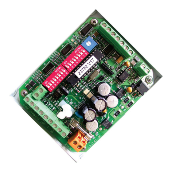
PCB Übersicht Abb. 3.1 Kontinuierlich: Nicht verwendet Zeitgesteuert: Dosierzeit: 1 ... 126 s Leitfähigkeitsgesteuert.: 0 ... 12,6 mS/cm (Faktor 1) (LF gesteuert) 0 ... 25,2 mS/cm (Faktor 2) Leermeldung (opt) Kapselschalter LF gesteuert: Kontinuierlich: Nicht verwendet - OFF: Faktor 1 Zeitgesteuert: Verzögerung: 0 ... -
Page 6: Funktionsbeschreibung, Betrieb Und Einstellungen
Funktionsbeschreibung, Betrieb und Einstellungen Die Steuerelektronik wird über einen externen Transformator (siehe Zubehörliste) mit Spannung versorgt, sobald das entsprechende Freigabesignal von der Geschirrspülmaschine (GSM) anliegt. Die grüne LED auf der Vorderseite der Einheit leuchtet ständig im Betriebsmodus, und blinkt im Modus Stand-By. Die Dosierung kann in den Betriebsarten "kontinuierlich gesteuert”, "zeitgesteuert”... -
Page 7: Einstellungen
4.2.2 Einstellungen Mode Verzögerung Dosierzeit Drehzahl (7=ON, 8=OFF) (z.B. 10 s) (z.B. 6 s) Analog Kapitel 4.2.3 Verzögerung (DIP-Schalter "Delay | Mode |”) (Betriebsart) festgelegt (Betriebsart) festgelegt 32 Sekunden 16 Sekunden 8 Sekunden 4 Sekunden 2 Sekunden 1 Sekunde 4.2.4 Dosierzeit: (DIP-Schalter "TIME/Titration”) Nicht verwendet Nicht verwendet... -
Page 8: Fehleranzeige
4.2.6 Fehleranzeige Die rote LED an der Front leuchtet und der Summer wird eingeschaltet, wenn der Pumpenmotor defekt ist (Kurzschluss). Durch Drücken der Taste "QUIT” wird der Summer ausgeschaltet. Die rote LED an der Front blinkt und der Summer wird eingeschaltet, wenn am Eingang IN2 Leermeldung (Kontakt geöffnet) erkannt wird. -
Page 9: Einstellungen
4.3.2 Einstellungen Titration Max. Dosierzeit Mode Drehzahl (z.B. 5,0 mS/cm) (z.B. 120 s) konduktive (2-Draht) Messzelle (7=OFF, 8=ON) Für Flüssigkeiten: Analog Kapitel Für Feststoff: induktive Messzelle (solid) (7=ON, 8=ON) Siehe Kapitel 4.3.3 4.3.3 Potentiometer für FESTSTOFF (AC-Ausgang) Intervalldauer (Übersteuerung) (MIN) (MAX) (MITTE) Konzentration... -
Page 10: Max. Dosierzeit: (Dip-Schalter "Delay | Mode |")
4.3.4 Max. Dosierzeit: (DIP-Schalter "Delay | Mode |”) Induktiv 2-Draht (Betriebsart) festgelegt (0=2-Draht, 1=induktiv) (Betriebsart) festgelegt 640 Sekunden 320 Sekunden 160 Sekunden 80 Sekunden 40 Sekunden 20 Sekunden Wenn alle "Delay” DIP-Schalter auf OFF stehen, beträgt die Dosierzeit 10 Sekunden 4.3.5 Titration: (DIP-Schalter "TIME/Titration”) Faktor 2... -
Page 11: Fehleranzeige
4.3.7 Fehleranzeige • Die rote LED an der Front leuchtet und der Summer wird eingeschaltet, wenn der Pumpenmotor defekt ist (Kurzschluss). Durch Drücken der Taste "QUIT” wird der Summer ausgeschaltet. • Nur bei induktiver Leitfähigkeitsmessung: Die rote LED an der Front leuchtet und der Summer wird eingeschaltet, wenn die Induktiv-Messzelle nicht angeschlossen oder defekt ist. -
Page 12: Montage Und Installation
Montage und Installation Vor der Installation Die folgenden Montage- und Installationsrichtlinien sind Vorschläge für die beste Methode Die unterschiedlichen Bedingungen und physikalischen Gegebenheiten bestimmen jedoch in der Praxis die Montage und Installation. HINWEIS Die Installation ist entsprechend den geltenden Vorschriften durchzuführen. Für einwandfreien Betrieb der Einheit darf der Abstand zwischen Einheit und Produktbehälter (max. -
Page 13: Schaltplan
Schaltplan Abb. 5.1 417101373_Ecodos-PCB.docx - 13 - Rev. 10-03.12... -
Page 14: Mögliche Freigabemodule (Anschluss An In1)
Mögliche Freigabemodule (Anschluss an IN1) 1. Mechanischer Kontakt (Kontakt geschlossen = System aktiviert) Abb. 5.2 2. Elektrisches Freigabemodul (Bestell-Nr.: 273075) oder Magnetfeldsensor (Bestell-Nr.: 273076) Magnetfeldsensor Übersicht: (273075) Anschlusskabel für Abb. 5.3 Freigabesignal (273055) Elektr. Freigabemodul (273076) Anschlusskabel für Freigabesignal (Enable-Cable) 273055 an PCB: Abb. -
Page 15: Wartungs- Und Reparaturanweisungen
Wartungs- und Reparaturanweisungen Wartungs- und Reparaturarbeiten dürfen nur von autorisierten Personen durchgeführt VORSICHT werden. Sicherstellen, dass die Stromversorgung der Geschirrspülmaschine unterbrochen ist. Nur die Original-Ersatzteile verwenden! Vor der Durchführung von Reparaturarbeiten muss die Einheit von der Stromversorgung WARNUNG getrennt werden.Nach jeder Reparatur muss eine Funktionsprüfung der Einheit durchgeführt werden. -
Page 16: Fehlersuche
Fehlersuche Fehler Mögliche Ursache Abhilfe Trafo und Verdrahtung prüfen, gegebenenfalls LED leuchtet nicht, wenn Trafo defekt, Verdrahtung defekt auswechseln an der Geschirrspülmaschine Platine defekt Platine austauschen (GSM) Spannung anliegt Pumpe arbeitet nicht / Messzelle nicht an Platine Zelle an "1 ... 7” bzw. "8 + 9” anschließen Magnetventil im angeschlossen Drahtbrücke zwischen "3”... -
Page 17: Ersatzteilliste
Ersatzteilliste Beschreibung Artikel Nr. Summer 418271009 Getriebemotor DC 24 v 417501924 *Transformator AC 240/24V, 15 W 418931008 *Konduktiv (2-draht) Leitfähigkeitsmesszelle 418811360 *Messkabel für konduktiv Leitfähigkeitsmesszelle (2-draht-Messzelle) 223752 *Induktivmesszelle (mit 0,2 m Kabel) 287409 * Induktivmesszelle (mit 3,0 m Kabel) 287407 * Induktivmesszelle (mit 6,0 m Kabel) 287408 *Verlängerungskabel (6,0m) -
Page 18: Technische Daten
Technische Daten Versorgungsspannung: AC 24 V,15 W, 50-60 Hz Sicherheitsart: gemäß Dosiereinheiten Schutzklasse: Eingänge: Stromversorgung "POWER AC24V”: Stromversorgung über externen Transformator (AC 24V, 15 W) (steckbar) Enable "IN1”: 5VDC-Kontakt, nicht galvanisch getrennt (TTL) Füllstand "IN2”: 5VDC-Kontakt, nicht galvanisch getrennt (TTL) Konduktiv Leitfähigkeitsmesszelle "P120”... - Page 19 Table of Contents General Extent of Warranty Contact Address / Manufacturer Safety General safety information Maintenance and repair work Emphases PCB Overview Operation Mode Functional description, operation and settings Continuous mode 4.1.1 Settings 4.1.2 Enable Signals Timed metering mode 4.2.1 Functional principal 4.2.2 Settings...
-
Page 20: General
Contact Address / Manufacturer. Transport Damage CAUTION If the Ecodos-PCB is found to have been damaged when it is unpacked, it should not be installed! WARNING Extent of Warranty All warranties concerning the operating safety, reliability and performance of the... -
Page 21: Safety
Safety warnings and emphases must be observed in all cases! WARNING General safety information Ecodos-PCB has been constructed and checked in accordance with DIN EN 61010- 1:2004-01 and left the factory in a safe, faultless technical condition. To keep the device in this condition and to ensure risk-free operation, the user must observe the instructions and warnings in this Operating Instruction. -
Page 22: Pcb Overview
PCB Overview Fig. 3.1 Continuous mode: Not used Timed mode: Dosing time: 1 ... 126 sec Conductivity mode: 0 ... 12,6 mS/cm (Factor 1) 0 ... 25,2 mS/cm (Factor 2) Low level (opt) Capsule switch Continuous mode: Not used Conductivity mode: Timed mode: Delay time: 0 ... -
Page 23: Functional Description, Operation And Settings
Functional description, operation and settings The control electronic is supplied with voltage via an external transformer (see accessory list) as soon as the corresponding enabling signal from the dishwasher is applied. The green LED at the front side of the unit lights up continuously in operation mode or is flashing in standby mode. -
Page 24: Settings
4.2.2 Settings Mode Speed Delay Dosage time (7=ON, 8=OFF) (e.g. 10 sec) (e.g. 6 sec) Analog chapter 4.2.3 Delay: (DIP switch “Delay | Mode |”) (Mode setting) Obligatory (Mode setting) Obligatory 32 seconds 16 seconds 8 seconds 4 seconds 2 seconds 1 second 4.2.4 Dosage time: (DIP switch “TIME/Titration”) -
Page 25: Fault Indication
4.2.6 Fault indication The red LED at the front side will light up and the buzzer will be activated if the pump motor has become defective (short circuit). Buzzer can be switched off by pressing “QUIT” button. The red LED at the front side will flash and the buzzer will be activated if a low level (contact open) will be detected at input IN2. -
Page 26: Settings
4.3.2 Settings Titration Max. dosage time Mode Speed (e.g. 5.0 mS/cm) (e.g. 120 sec) 2-wire probe (7=OFF, 8=ON) For liquid version: Analog chapter inductive probe For solid version: (7=ON, 8=ON) See chapter 4.3.3 4.3.3 Speed potentiometer for SOLID version (AC-output) Interval time (Overshoot behaviour) Concentration... -
Page 27: Titration: (Dip Switch "Time/Titration")
4.3.4 Max. dosage time: (DIP switch “Delay | Mode |”) Inductive Mode 2-wire Mode (Mode setting) Obligatory (0=2-wire, 1=inductive) (Mode setting) Obligatory 640 seconds 320 seconds 160 seconds 80 seconds 40 seconds 20 seconds When all “Delay” DIP-switches are OFF, the dosage time is 10 seconds 4.3.5 Titration: (DIP switch “TIME/Titration”) Factor 2... -
Page 28: Fault Indication
4.3.7 Fault indication • The red LED at the front side will light up and the buzzer will be activated, if the pump motor has become defective (short circuit). Buzzer can be switched off by pressing “QUIT” button. • Only w. inductive mode: The red LED at the front side will light up and the buzzer will be activated if the inductive probe is not connected or becomes defective. -
Page 29: Mounting And Installation
Mounting and installation Pre-installation requirements Mounting and installation guidelines will be suggested as the preferred method. However varying types of conditions and surrounding physical environments will dictate the actual mounting and installation. NOTE The installation must be in accordance with all local regulations. In order to ensure correct operation of the unit, the following dimensions must not be exceeded. -
Page 30: Wiring Diagram
Wiring diagram fig. 5.1 417101373_Ecodos-PCB.docx - 30 - Rev. 10-03.12... -
Page 31: Possible Input Modules (Connection At In1)
Possible input modules (connection at IN1) 1. Mechanical contact (contact closed = system activated) fig. 5.2 2. Electrical enable module (part no: 273075) or magnetic field sensor (part no: 273076) Magnetic field sensor Overview: (273075) Enable cable fig. 5.3 (273055) Electrical enable module Connection enable cable 273055 to PCB: fig. -
Page 32: Maintenance And Repair Instructions
Maintenance and repair instructions Any service and repair work must be carried out by authorized personnel only. CAUTION Ensure, that the power supply from the dishwasher is interrupted. Only the original spare parts must be used. WARNING Before any repair work is carried out, the unit must be disconnected from it’s power source. Following each repair work a functional test of the unit must be performed. -
Page 33: Trouble Shooting
Trouble shooting Symptom Possible cause Corrective action LED does not illuminate Transformer defective, wiring Check transformer, wiring and replace if when power is applied from defective required the dishwasher PCB defective Replace PCB Measuring probe not connected Connect probe to “1 ... 7” resp. -
Page 34: Spare Parts List
Spare parts list Description Item No. Buzzer 418271009 Gear motor DC 24 v 417501924 Transformer AC 240/24 V, 15 W 418931008 2-wire conductivity probe 418811360 Measuring cable for 2-wire probe 223752 Inductive sensor (with 0.2 m cable) 287409 Inductive sensor (with 3.0 m cable) 287407 Inductive sensor (with 6.0 m cable) 287408... -
Page 35: Technical Data
Technical data Supply voltage: AC 24 V,15 W, 50-60 Hz Safety type: According to dosing units Protective class: Inputs: Power suppy “POWER AC24V”: Power supply via external transformer (AC 24V, 15 W) (p/o unit) Enable “IN1”: 5VDC-contact, not galvanic isolated (TTL) Low level “IN2”: 5VDC-contact, not galvanic isolated (TTL) Conductivity sensor 2-wire “8 + 9”:... - Page 37 Letzte Änderung: 22.03.2012 last changing: © Copyright ECOLAB Engineering GmbH, 2011 All rights reserved Alle Rechte vorbehalten. Nachdruck, auch auszugsweise, nur mit Genehmigung der Firma ECOLAB Engineering GmbH gestattet. Reproduction, also in part, only with permission of ECOLAB Engineering GmbH.
Need help?
Do you have a question about the Ecodos-PCB and is the answer not in the manual?
Questions and answers