
Subscribe to Our Youtube Channel
Related Manuals for Ecolab Ecoplus-PCB


Summary of Contents for Ecolab Ecoplus-PCB
- Page 1 Betriebsanleitung Operating Instruction Ecoplus-PCB Abb. 0.1 / Fig. 0.1 Deutsch English 417101726_Ecoplus_PCB.docx - 1 - Rev. 02-02.2012...
-
Page 2: Table Of Contents
Inhaltsverzeichnis Allgemeines ........................3 Transportschäden ..........................3 Gewährleistungsumfang ........................3 Kontaktadresse / Hersteller ........................3 Sicherheit ........................... 4 Allgemeines ............................4 Wartung und Reparatur ......................... 4 Hervorhebungen ............................ 4 Spezielle Sicherheitsinformationen für Wartungs- und Reparaturarbeiten ........... 4 PCB Übersicht ........................5 Hauptplatine ............................ -
Page 3: Allgemeines
Allgemeines Diese Betriebsanleitung enthält alle Anweisungen zur Installation, Inbetriebnahme, Wartung und Reparatur der Ecoplus-PCB. Bei den deutschsprachigen Kapiteln dieser Anleitung handelt es sich um die HINWEIS ORIGINALBETRIEBSANLEITUNG, die rechtlich relevant ist. Alle anderen Sprachen sind Übersetzungen der ORIGINALBETRIEBSANLEITUNG. Bitte diese Anleitung sorgfältig lesen und als Referenz aufbewahren. -
Page 4: Sicherheit
Die Sicherheitshinweise und Hervorhebungen sind in jedem Fall zu beachten! WARNUNG Allgemeines Ecoplus-PCB ist gemäß DIN EN 61010-1:2004-01, gebaut und geprüft und hat das Werk in sicherheitstechnisch einwandfreiem Zustand verlassen. Um diesen Zustand zu erhalten, und einen gefahrlosen Betrieb sicherzustellen, muss der Anwender die Hinweise und Warnvermerke beachten, die in dieser Betriebsanleitung enthalten sind. -
Page 5: Pcb Übersicht
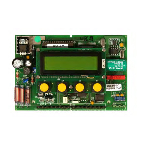
PCB Übersicht Hauptplatine EEPROM (P/N 223568) “P” / Plug 18, 19 “L” / Plug 18, 19 “V” / Plug 17, 18 SQP Add-On-Board P/N: 223551 Ausgänge: - Schlauchquetschpumpe 24 VDC - RS232 Eingänge: - Freigabeeingänge - Leermeldung „N“ Add-On-Board P/N: 223552 Muß... -
Page 6: Tastenfunktionen
Tastenfunktionen Service-, Parametrier- und Betriebsebene Tasten Konfigurationsebene Aktivierung des Menüs Aufrufen eines Menüs. „INPUT ACCESS CODE“ NEXT NEXT Rückkehren zur Ausgangsebene. (=Zugangscode). Reinigerausgang für 30 sec abschalten. Aufrufen eines Menüs. (Sicherheitsfunktion speziell in Blättern innerhalb eines Menüs. Verbindung mit Solid-Ausspülgeräten). Bewegen des Cursors. -
Page 7: Programmierstrukturen
Programmierstrukturen Ecoplus V/P Im Wechsel Programmierstruktur Programmierstruktur ECOPLUS V(P) alle 5 sec. ECOPLUS V/P ECOPLUS V/P 12:00 Ab Software V 2.00 Passwort ---- Falls Code ACCESS CODE falsch Zurück zur - - - - Betriebsebene EXIT Parametrierung Service Konfiguration Funktionen... -
Page 8: Service Funktionen
4.2.1 Service Funktionen Programmierstruktur Programmierstruktur ECOPLUS (alle Varianten) ECOPLUS (alle Varianten) Ab Software v2.00 Service Funktionen SERVICE FUNCTIONS Anzeige OK: Standard 99: Erweitert DISPLAY REPORT MANUAL DOSING ACCESS CODE FUNCTIONS FUNCTIONS FUNCTIONS Manuelle Passwort Dosierfunktionen Funktionen Anzeige/Druck Funktionen DISPLAY DETERGENT OUTPUT Reinigerausgang CONSUMPTION STAT Ein-/Ausschalten... -
Page 9: 4.2.2.1 Kalibrierung
4.2.2.1 Kalibrierung Programmierstruktur Programmierstruktur ECOPLUS (alle Varianten) ECOPLUS (alle Varianten) Ab Software v2.00 Kalibrier- funktionen CALIBRATION FUNCTIONS Reiniger- Klarspüler- Additiv- Nullpunkt-Kalibrierung Kalibrierung Kalibrierung einheit einheit einheit Messzelle Waschtemperatur Klarspülertemperatur DETERGENT UNIT RINSE AID UNIT 3RD PROD UNIT ZERO CALIBRATION CALIBRATE WASH CALIBRATE RINSE... -
Page 10: 4.2.2.2 Alarm, Dosierparameter
4.2.2.2 Alarm, Dosierparameter Programmierstruktur Programmierstruktur ECOPLUS (alle Varianten) ECOPLUS (alle Varianten) Dosier- Ab Software v2.00 einstellungen Alarm- DEFINE METERING ALARM CONTROL einstellungen SETTINGS SETUP Standard Einstellungen? Anzeige- und Grenzwerte STANDARD MESSAGE AND SETTINGS ? DELAY SETTINGS Oder (bei flüssig): Alarmwiederholzeit EMPTY DETERGENT “Leermeldung Reiniger”... -
Page 11: Konfiguration
4.2.3 Konfiguration Programmierstruktur Programmierstruktur ECOPLUS (alle Varianten) ECOPLUS (alle Varianten) Ab Software v2.00 Legende: CONFIGURATION Konfiguration FUNCTIONS Basis ENGLISH “T” oder “X”-Version FRANÇAIS DEUTSCH ITALIANO NEDERLANDS Sprache für Fehlermeldungen MESSAGE LANGUAGE ESPAÑIOL Betriebsdaten ENGLISH Dosiermodus Im zeitgesteuerten Modus wird der Ausgang SOLID ... -
Page 12: Kundendaten
4.2.4 Kundendaten Kundendaten Kundendaten ECOPLUS ECOPLUS Software v2.00 ECOPLUS V Im Wechsel 01.01.07 alle 5 sec. 12:00 Ansicht je nach Gerätetyp unterschiedlich START: 01.01.07 12:00 Taktzähler 16777216 Nur bei System mit externer Nachspülzeit Klarspülerfreigabe 1193046:28 hrs Um von einem Menü zum Nächsten zu gelangen: Taste drücken. -
Page 13: Einstellung Der Reiniger-Konzentration
Einstellung der Reiniger-Konzentration In obigem Diagramm ist die Konzentrationseinstellung für 2 g/l (*) beispielhaft dargestellt. HINWEIS Die Werte in der Titrationstabelle gelten ebenso als Beispiel. Maßgeblich sind die für das verwendete Produkt gültigen Titrationstabellen. 417101726_Ecoplus_PCB.docx - 13 - Rev. 02-02.2012... -
Page 14: Anschlusspläne
Anschlusspläne Ecoplus V Ecoplus VXRi 417101726_Ecoplus_PCB.docx - 14 - Rev. 02-02.2012... -
Page 15: Ecoplus Vxn
Ecoplus VXN Ecoplus P 417101726_Ecoplus_PCB.docx - 15 - Rev. 02-02.2012... -
Page 16: Ecoplus Pxri
Ecoplus PXRi Ecoplus PXN 417101726_Ecoplus_PCB.docx - 16 - Rev. 02-02.2012... -
Page 17: Ecoplus Lxri/Ltri
Ecoplus LXRi/LTRi HINWEIS „T“-Variante ist ohne RS232-Schnittstelle Ecoplus EXN 417101726_Ecoplus_PCB.docx - 17 - Rev. 02-02.2012... -
Page 18: Fehlerbehandlung
Fehlerbehandlung Der akustische Alarm kann durch Drücken einer beliebigen Taste an der Frontseite ausgeschaltet werden. Die Alarmanzeige im Display bleibt jedoch solange erhalten, bis der Fehler behoben ist. Display-Anzeigen Fehlerursache Behebung Reiniger-Vorratsgebinde leer Neues Gebinde anschließen. Alarmverzögerungszeit tmax. (DET. DELAY KEIN REINIGER Alarmverzögerungszeit verändern. -
Page 19: Ersatzteilliste
Verlängerungskabel 6.0 m Für Klarspültemperaturfühler (3-Pol) 418463276 Freigabemodul Typ 1 (Gemeinsammer “N”) 223563 Freigabemodul Typ 2 (3 X L/N Separat) 223564 PC Kabel RS232 223565 RS232 zu USB Wandler 418832011 Kurzanleitung „Ecoplus-PCB“ Free download via Internet 417101726_Ecoplus_PCB.docx - 19 - Rev. 02-02.2012... -
Page 20: Technische Daten
Technische Daten Versorgungspannung: 2x12 V, 50-60 Hz Leistung: Basisgerät ohne Add-On-Board: 15 W Mit SQP Add-On Board 32355103: 30 W Mit “KA”-Add-On Board 32355202: Max. 45 W Schutzart: Gemäß Dosiergeräte Schutzklasse: III (ausschließlich Platine, ohne Trafo) - Spannungsversorgung, 2 x 12 VAC - Induktive Messzelle mit integriertem Waschtanktemperaturfühler Motherboard: - Klarspülertemperaturfühler... - Page 21 Table of Contents General Points ......................... 22 Transport Damage ..........................22 Extent of Warranty ..........................22 Contact Address / Manufacturer ......................22 Safety ..........................23 General Points ............................. 23 Maintenance and Repair ........................23 Emphases ............................23 Special Safety Information for Maintenance and Repair Work ............23 PCB Overview ........................
-
Page 22: General Points
General Points This Operating Instruction contains all required information on installing, starting up, maintaining, and repairing the Ecoplus-PCB. The German sections of this manual constitute the ORIGINAL OPERATING NOTE INSTRUCTIONS and take legal precedence. All other languages are translations of the ORIGINAL OPERATING INSTRUCTIONS. -
Page 23: Safety
Safety warnings and emphases must be observed in all cases! WARNING General Points Ecoplus-PCB has been constructed and checked in accordance with DIN EN 61010- 1:2004-01 and left the factory in a safe, faultless technical condition. To keep the device in this condition and to ensure risk-free operation, the user must observe the instructions and warnings in this Operating Instruction. -
Page 24: Pcb Overview
PCB Overview Motherboard EEPROM (P/N 223568) ‘P’ / Plug 18, 19 ‘L’ / Plug 18, 19 ‘V’ / Plug 17, 18 Peristaltic Pump Add-On Board P/N: 223551 Outputs: - 24 V DC peristaltic pump - RS232 Inputs: - Enable inputs - Empty signal 'N’... -
Page 25: Key Functions
Key functions Service, parameter, and Operating level Keys configuration level For activating the ‘INPUT ACCESS For calling a menu. NEXT CODE’ menu. For returning to the start level. For switching off the detergent output for For calling a menu. 30 seconds For scrolling within a menu. -
Page 26: Programming Structures
Programming Structures Ecoplus V/P Alternating ECOPLUS V(P) each 5 sec. Programming Structure Programming Structure 12:00 ECOPLUS V/P ECOPLUS V/P Software v2.00 if access code ACCESS CODE is wrong - - - - EXIT SERVICE PARAMETER CONFIGURATION ENGLISH FRANÇAIS FUNCTIONS FUNCTIONS... -
Page 27: Service Functions
4.2.1 Service Functions Programming Structure Programming Structure ECOPLUS (complete) ECOPLUS (complete) Software v2.00 SERVICE FUNCTIONS DISPLAY REPORT MANUAL DOSING ACCESS CODE FUNCTIONS FUNCTIONS FUNCTIONS DISPLAY DETERGENT OUTPUT CONSUMPTION STAT (if previously deactivated) (if previously activated) DISPLAY FAULT FLUSHING OUTPUT MESSAGE LOG ACTIVATE DEACTIVATE CHANGE... -
Page 28: 4.2.2.1 Calibration
4.2.2.1 Calibration Programming Structure Programming Structure ECOPLUS (complete) ECOPLUS (complete) Software v2.00 CALIBRATION FUNCTIONS DETERGENT UNIT RINSE AID UNIT 3RD PROD. UNIT ZERO CALIBRATION CALIBRATE WASH CALIBRATE RINSE 04.50 kg/cap 00.00 ml/min 00.00 ml/min CONDUCT. -
Page 29: 4.2.2.2 Alarm And Dosing Parameters
4.2.2.2 Alarm and Dosing Parameters Programming Structure Programming Structure ECOPLUS (complete) ECOPLUS (complete) Software v2.00 DEFINE METERING ALARM CONTROL SETTINGS SETUP STANDARD MESSAGE AND SETTINGS ? DELAY SETTINGS EMPTY DETERGENT PER1 ON = 06:00 SPECIAL SETTINGS ALARM REPEAT CAPSULE SENSOR ... -
Page 30: Configuration
4.2.3 Configuration Programming Structure Programming Structure ECOPLUS (complete) ECOPLUS (complete) Software v2.00 Legend: CONFIGURATION FUNCTIONS Basic ENGLISH “T” or “X”-Version FRANÇAIS DEUTSCH ITALIANO NEDERLANDS MESSAGE LANGUAGE ESPAÑIOL ENGLISH DET.DOS.MODE SOLID In the time controlled mode, the solenoid valve for ... -
Page 31: Customer Data
4.2.4 Customer Data CUSTOMER REPORT CUSTOMER REPORT FUNCTIONS ECOPLUS FUNCTIONS ECOPLUS Software v2.00 ECOPLUS V Alternating 01.01.07 each 5 sec. 12:00 View depends on Unit type START: 01.01.07 12:00 Language: TAKTZÄHLER GB: CYCLE COUNTER CYCLE COUNTER 16777216 Only at systems with external RINSE ON TIME RINSE enable 1193046:28 hrs... -
Page 32: Setting The Detergent Concentration
Setting the Detergent Concentration The diagram above shows an example concentration setting of 2 g/l (*). The values in the NOTE titration table are also meant as examples. The titration tables for the product used take priority over these example values. 417101726_Ecoplus_PCB.docx - 32 - Rev. -
Page 33: Connection Diagrams
Connection Diagrams Ecoplus V Ecoplus VXRi 417101726_Ecoplus_PCB.docx - 33 - Rev. 02-02.2012... -
Page 34: Ecoplus Vxn
Ecoplus VXN Ecoplus P 417101726_Ecoplus_PCB.docx - 34 - Rev. 02-02.2012... -
Page 35: Ecoplus Pxri
Ecoplus PXRi Ecoplus PXN 417101726_Ecoplus_PCB.docx - 35 - Rev. 02-02.2012... -
Page 36: Ecoplus Lxri/Ltri
Ecoplus LXRi/LTRi NOTE The ‘T’ variant has no RS232 interface. Ecoplus EXN 417101726_Ecoplus_PCB.docx - 36 - Rev. 02-02.2012... -
Page 37: Fault Handling
Fault Handling You can switch off the acoustic alarm by pressing any key on the front of the device. However, the alarm display on the screen remains visible until you eliminate the fault. Display screen message Cause of fault Remedy The detergent storage unit is empty. -
Page 38: Spare Parts List
Spare Parts List Description Article No. Buzzer 418271009 Spare part PCB 223557 Current software (EPROM) 223568 Add-On Board for peristaltic pump 223551 Add-On Board with AC outputs (Type Ka) 223552 AC 240 / 2 x 12 v Transformer, 15 w, 2.5 m Prim, 4.5 m Sec 418931008 AC 240 / 2 x 12 v Transformer, 30 w, 2.5 m Prim, 4.5 m Sec 418931010... -
Page 39: Technical Data
Technical Data Power supply: 2x12 V, 50-60 Hz Power: Motherboard w/o add-on board: 15 W With 32355103 peristaltic pump add-on 30 W board: With 32355202 KA add-on board: Max. 45 W Protection class: As appropriate for metering devices Protection rating: III (except PCB, without transformer) - 2 x 12 V AC power supply - Inductive measuring cell with integrated washing tank temperature... - Page 40 Letzte Änderung: 29.02.2012 last changing: © Copyright ECOLAB Engineering GmbH, 2011 All rights reserved Alle Rechte vorbehalten. Nachdruck, auch auszugsweise, nur mit Genehmigung der Firma ECOLAB Engineering GmbH gestattet. Reproduction, also in part, only with permission of ECOLAB Engineering GmbH.
Need help?
Do you have a question about the Ecoplus-PCB and is the answer not in the manual?
Questions and answers