Advertisement
Quick Links
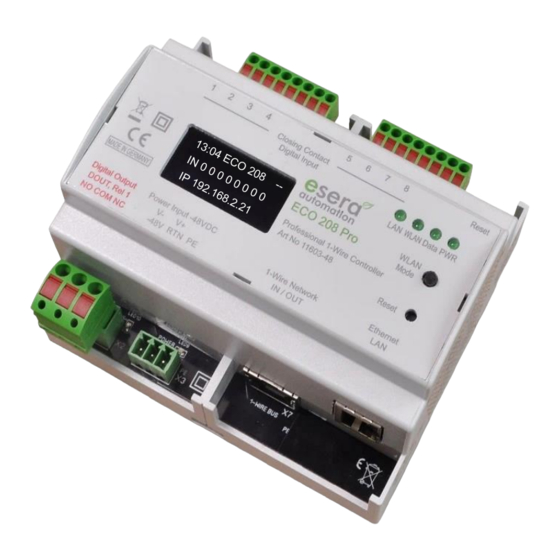
Art.No.11603-48
The ECO 208 PRO controller is a high-
performance 1-Wire interface of the 3rd generation
for sensors and actuators in the industrial and
telecommunication sector.
fully automatic integration of sensors* and
actuators*
WLAN and LAN Modbus TCP data interface
max. 20 Modbus data connections
OLED display
8x digital inputs
1 x relay output / alarm output
Plug and Play interface for up to 30 sensors (e.g.
temperature, humidity, air quality, gas sensors)
Web server for configuration, Debug and Firmware
updates
robust industrial design
extensive software support
power supply -48VDC
Auto-E-Connect Support Level I to III
Fast readout of all 1-Wire Devices in a
1-2 seconds cycle
Basic unit for many industrial and telecommunication solutions
Designed for small to large 1-Wire Networks
Management of all ESERA and many standard
1-Wire Modules and Chips
Note
Before starting the installation of the ECO 208 PRO and putting the unit into operation, read this
operating manual carefully to the end, especially the section on safety instructions.
All settings and configurations of the ECO 208 PRO are carried out with the software Config Tool 3.
You can find this software on the ESERA website. Please refer to the operating instructions for
Config Tool 3, which can be found within the Config Tool 3 software under the
"HELP/SUPPORT" tab.
* if the sensor or actuator supports Auto-E-Connect. For details, please refer to the operating instructions of the sensor or actuator.
All rights reserved. Reproduction as well as electronic duplication of this user guide, complete or in part, requires the written consent of
ESERA GmbH. Errors and technical modification subject to change. ESERA GmbH 2021
www.esera.de
User Guide
ECO 208 PRO
Professional 1-Wire Controller
11603-48 V1.0 R1.1 Manual
Page 1 of 18
Advertisement

Subscribe to Our Youtube Channel
Related Manuals for esera automation ECO 208 PRO


Summary of Contents for esera automation ECO 208 PRO
- Page 1 All settings and configurations of the ECO 208 PRO are carried out with the software Config Tool 3. You can find this software on the ESERA website. Please refer to the operating instructions for Config Tool 3, which can be found within the Config Tool 3 software under the "HELP/SUPPORT"...
- Page 2 (referred to collectively as Devices in the following). Up to 5 data values can be output per 1-Wire device. This means that the ECO 208 PRO can provide up to 150 data values, which is a very large number and a very good price per data value ratio.
- Page 3 OWD number. This automatic registration works up to the maximum possible OWD number of the ECO Controller. Sensorfinder Function: The ECO 208 PRO can activate a status LED within the ESERA 1-Wire Pro sensors*. The status LED flashes or lights up permanently for a certain time. This makes the detection of a device in a 1-Wire Network much easier.
- Page 4 Technical data Ethernet interface: - TCP/IP, Socket Server - 10/100 MBit/s Ethernet Interface, WLAN: 802.11 b/g, LAN 10/100MBit/s - up to 20 data connections for ModbusTCP - Auto Negotiation (Full-duplex and Half-duplex) - Auto MDI/MDIX - Support for DHCP and fixed IP-Adress Auto-E-Connect: Level I to III supported Data, Firmware Update...
- Page 5 Art.No.11603-48 LED Green WLAN WLAN - Network Status LED lights up when a WLAN Network connection is established flashes when the WLAN access point is activated and a direct connection is possible. Connection plan Module top side: Digital inputs, normally open contacts Reset Button: Reset Button for recovery Note...
- Page 6 Module bottom side: Digital Output (Changeover Contact), Power Supply, Sensor Bus Interface (1-Wire) and Ethernet Connection. Note The PE connection of the ECO 208 PRO should be connected to earth potential (PE). This establishes a functional earth Note The module may only be operated at the voltages and under the ambient conditions specified for it. The operating position of the unit is arbitrary.
- Page 7 Art.No.11603-48 Connection example 1-Wire Multisensors * if the sensor or actuator supports Auto-E-Connect. For details, please refer to the operating instructions of the sensor or actuator. All rights reserved. Reproduction as well as electronic duplication of this user guide, complete or in part, requires the written consent of ESERA GmbH.
- Page 8 Hercules oder Putty) via UDP / TCP/IP. to exchange data with the ECO 208 PRO and to carry out the configuration. Details on the communication commands can be found in the document "Programming Manual", which you can find in the download area of the ECO 208 PRO and within the Config Tool 3 software.
- Page 9 Your desired protocol not included? The ECO 208 PRO is extremely powerful due to the Maxi data interface used. On request, we can also integrate other interface protocols. We would be happy to provide you with a quotation for this. Contact us via the technical support, support@esera.de.
- Page 10 Interface configuration Modbus/TCP, Maxi Interface Important, at present the configuration of the Ethernet interfaces is only possible via the web interface. The IP address for starting the web server is shown on the unit display or can be found in the system overview of the router / DHCP server.
- Page 11 Art.No.11603-48 14.3 Web server, Home page (Main Page), Maxi Interface The Main Page provides a selection of options for configuring the Ethernet interface. The various buttons (selection keys) take you to the corresponding submenus. These are described on the following pages. Ethernet Interface Setting This button takes you to the menu for setting the IP address, SubNet and gateway number.
- Page 12 14.4 Web server, Interface Setting, Maxi Interface Use the "Interface Setting" web page to set the basic settings for the Maxi interface. In this menu, the operating mode of the Ethernet interface, TCP Server or UDP, of the ECO Controller is configured.
- Page 13 Art.No.11603-48 14.5 Web server, Protocol Settings, Maxi Interface The data protocol settings for the 5 data interfaces can be made on this page. Currently, 1 x ASCII and 4 x Modbus/TCP are available for the Maxi interface. On request, further protocols can be integrated here and made selectable. We will be happy to provide you with an offer for the integration of further protocols.
- Page 14 14.6 Web server, Disable AP Mode, Maxi Interface In addition to a LAN interface, the ECO Controller with Maxi Interface also has a connectable WLAN access point that you can use for configuration and data communication. The access point is activated by a button on the unit's surface.
- Page 15 The above statements on 1-Wire are hints and tips and do not describe any product property or represent any guaranteed product property of the ECO 208 PRO. Information on the basics and tips on the 1-Wire Bus system can also be found in the ESERA Online Shop under https://www.esera.de/1-wire-grundlagen/...
- Page 16 Pressing the reset button does not correspond to an interruption of the power supply. Example for integration in Codesys We would be pleased to provide you with a test software for the integration of the ECO 208 PRO into the PLC software Codesys. Please contact our technical support under support@esera.de...
- Page 17 Art.No.11603-48 Your software not listed? Due to the text protocol used, the ECO 208 PRO can be integrated extremely universally into many devices and software solutions. Operating conditions The module may only be operated at the voltages and under the ambient conditions specified for it. The unit may be operated in any position.
-
Page 18: Warranty
Warranty ESERA GmbH guarantees that the goods sold at the time of transfer of risk to be free from material and workmanship defects and have the contractually assured characteristics. The statutory warranty period of two years begins from date of invoice.
Need help?
Do you have a question about the ECO 208 PRO and is the answer not in the manual?
Questions and answers