Advertisement
Quick Links
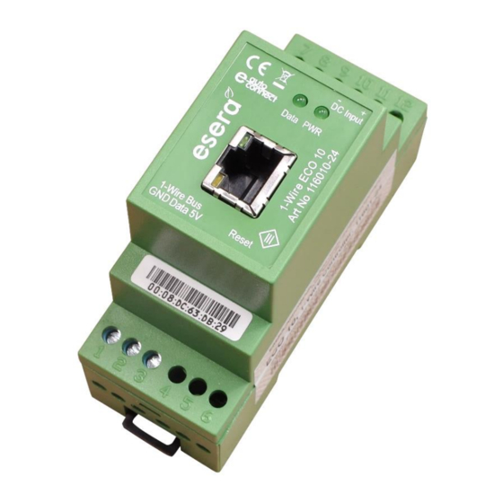
Art. No. 11601-24
The ECO 10 1-Wire Controller represents a high-
performance 3rd generation 1-Wire Interface for
sensors and actuators
Fully automatic integration of sensors* and
actuators*
Auto-E-Connect Support Level I and II
1-Wire Controller for autonomous communication
and updating of the 1-Wire Network.
Fast readout of all 1-Wire Components in a
1-2 seconds cycle
Cyclic output of the processed 1-Wire data in plain
text
Data communication via socket server/client, TCP
or UDP
Designed for small to large 1-Wire Networks
Power supply of the 1-Wire Network
Top-hat rail housing for control cabinet installation
Wide supply voltage range
Management of all ESERA and many standard
1-Wire Modules and Chips
Note
Before you start assembling the ECO 10 and put the unit into operation, read this operating manual
thoroughly, especially the section on safety instructions.
All settings and configurations of the ECO 10 are carried out with the Config Tool 3 software.
You can find this software on the ESERA website. Please refer to the operating instructions for Config
Tool 3, which you will find under the "HELP/SUPPORT" tab within the Config Tool 3 software.
* if the sensor or actuator supports Auto-E-Connect. For details, please refer to the operating instructions of the sensor or actuator.
All rights reserved. Reproduction as well as electronic duplication of this user guide, complete or in part, requires the written consent of
ESERA GmbH. Errors and technical modification subject to change. ESERA GmbH 2021
www.esera.de
User Guide
ECO 10 1-Wire Controller
Professional 1-Wire Controller
of the 3rd Generation
11601-24 V1.0 R1.1 Manual
Page 1 of 13
Advertisement

Subscribe to Our Youtube Channel
Related Manuals for esera automation ECO 10


Summary of Contents for esera automation ECO 10
- Page 1 1-Wire Modules and Chips Note Before you start assembling the ECO 10 and put the unit into operation, read this operating manual thoroughly, especially the section on safety instructions. All settings and configurations of the ECO 10 are carried out with the Config Tool 3 software.
- Page 2 Devices). Up to 5 data values can be output per 1-Wire Device. This means that the ECO 10 can provide up to 150 data values, which is a very large number and a very good price per data value ratio.
- Page 3 OWD number. This automatic login works up to the maximum possible OWD number of the ECO Controller. Sensorfinder Function: The ECO 10 can activate a status LED within the ESERA 1-Wire Pro sensors*. The status LED flashes or lights up permanently for a certain time. This makes it much easier to detect a device in a 1-Wire Network.
- Page 4 Technical data Ethernet interface: TCP/IP or UDP, Socket Server or Client - 10/100 MBit Ethernet Interface (RJ45) - Auto Negotiation (Full-duplex and Half-duplex) - Auto MDI/MDIX - Support für DHCP and fixed IP-Adresse Auto-E-Connect: Level I and II supported Auto-E-Connect Level III is only supported from ECO 100 onwards Data, Firmware Update and Configuration ESERA Config Tool 3...
- Page 5 This keystroke does not correspond to an interruption of the power supply. Note The Minus pole of the supply voltage / power supply unit of the ECO 10 should be connected to earth potential (PE). This establishes a functional earth Note The module may only be operated at the voltages and under the ambient conditions specified for it.
- Page 6 Connection example 1-Wire Multisensor Connection example only iButton reading unit * if the sensor or actuator supports Auto-E-Connect. For details, please refer to the operating instructions of the sensor or actuator. All rights reserved. Reproduction as well as electronic duplication of this user guide, complete or in part, requires the written consent of ESERA GmbH.
- Page 7 Art. No. 11601-24 Connection example with iButton and/or RFID reading unit * if the sensor or actuator supports Auto-E-Connect. For details, please refer to the operating instructions of the sensor or actuator. All rights reserved. Reproduction as well as electronic duplication of this user guide, complete or in part, requires the written consent of ESERA GmbH.
- Page 8 Connection example 1-Wire Hub III, sensors and actuators * if the sensor or actuator supports Auto-E-Connect. For details, please refer to the operating instructions of the sensor or actuator. All rights reserved. Reproduction as well as electronic duplication of this user guide, complete or in part, requires the written consent of ESERA GmbH.
- Page 9 15.1 ESERA ASCII Text protocol The ECO 10 provides a protocol in ASCII format. The ESERA text protocol in ASCII format can be used very easily for configuration and analysis. Special emphasis was placed on good readability and traceability. The ESERA text protocol works with "GET"...
- Page 10 The above statements on 1-Wire are hints and tips and do not describe any product property or represent any guaranteed product property of the ECO 10. Information on the basics and tips on the 1-Wire Bus system can also be found in the ESERA Online Shop under https://www.esera.de/1-wire-grundlagen/...
- Page 11 Example for Integration in Loxone Via the shop we provide a sample project for the simple integration of the ECO 10 into the Loxone Miniserver. This allows you to expand the Miniserver with many 1-Wire functions. Details can be found on the ESERA website under "Compatible controllers / Control units / Loxone integration".
- Page 12 Your software not listed? Due to the text protocol used, the ECO 10 can be integrated extremely universally into many devices and software solutions. Operating conditions The module may only be operated at the voltages and under the ambient conditions specified for it. The unit may be operated in any position.
-
Page 13: Warranty
Art. No. 11601-24 Warranty ESERA GmbH guarantees that the goods sold at the time of transfer of risk to be free from material and workmanship defects and have the contractually assured characteristics. The statutory warranty period of two years begins from date of invoice.
Need help?
Do you have a question about the ECO 10 and is the answer not in the manual?
Questions and answers