Advertisement
Quick Links
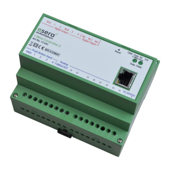
Art. No. 11340
1-Wire Controller / Gateway for autonomous
communication among SPS and a 1-Wire Sensor and
Actuator Network
Fast readout of all 1-Wire devices in
1-2 seconds cycle
Data output as ASCII text protocol
Processed sensor and actuator data
Status for each sensor and actuator can be called up
Comfortable configuration program
No additional drivers necessary
Power supply for 1-Wire Network
Designed for all 1-Wire Network sizes
Top-hat rail housing for control cabinet installation
Management of all ESERA-Automation and many
Standard 1-Wire Sensors and Actuators (e.g. switching
modules)
1
Introduction
Before you start assembling the 1-Wire Controller 2 and before you take the device into operation, please
read this assembly and operating instruction carefully to the end, especially the section referring to the safety
notes.
2
Product description
You can communicate with your smart home or industrial controller, e.g. ESERA Station, IP-Symcon,
Loxone or FHEM via TCP or UDP protocol with the 1-Wire Controller 2.
Autonomous management
The 1-Wire Controller 2 is designed for the autonomous management of a 1-Wire Network. You no longer
need to worry about 1-Wire commands or formulas for evaluating sensor data. The 1-Wire Controller 2
automatically scans the 1-Wire Network for new sensors and actuators and provides the corresponding data
in plain text via ASCII protocol, depending on the device found.
Formatted data output
The 1-Wire Controller 2 prepares sensor and actuator data that have been checked for plausibility, e.g. for
temperature sensors in °C with 2 decimal places. Only a division by 100 is necessary. Within the 1-Wire
Controller 2, product-specific conversion formulas are available for almost all 1-Wire sensors or actuators offered
by ESERA.
Designed for all 1-Wire Networks
The 1-Wire interface of the 1-Wire Controller 2 is specially designed to safely operate all sizes of 1-Wire
Networks, even with long cable runs. 1-Wire sensors can be operated simultaneously in parasitic or normal
mode.
The currently strongest 1-Wire interface for maximum data security, even for complex network structures,
has been installed.
All rights reserved. Reproduction as well as electronic duplication of this user guide, complete or in part, requires the written consent of
ESERA GmbH. Errors and technical modification subject to change. ESERA GmbH, ESERA-Automation 2020
www.esera.de
User Guide
1-Wire Controller 2
11340 V2.0 R1.0 Manual
Page 1 of 9
Advertisement

Subscribe to Our Youtube Channel
Related Manuals for esera automation Auto-E-Connect 11340


Summary of Contents for esera automation Auto-E-Connect 11340
- Page 1 Art. No. 11340 User Guide 1-Wire Controller 2 1-Wire Controller / Gateway for autonomous communication among SPS and a 1-Wire Sensor and Actuator Network Fast readout of all 1-Wire devices in 1-2 seconds cycle Data output as ASCII text protocol ...
-
Page 2: Ambient Conditions
1-Wire Controller 2 configuration For the configuration of the 1-Wire Controller 2, we provide a very powerful and user-friendly software (Config Tool 3) free of charge. Within the software you have the complete documentation at hand at any time and up-to-date, as it is automatically updated via the Internet. We provide the software via the article download area of our website and via the configuration software ESERA Config Tool 3. -
Page 3: Display Led
Art. No. 11340 Conformity EN 50090-2-2 EN 61000-4-2, ESD EN 61000-4-3, HF EN 61000-4-4, Burst EN 61000-4-5, Surge EN 61000-6-1, Noise immunity EN 61000-6-3, Interference radiation RoHS Display LED The module has various display LEDs. In the following the function of the displays Display Description Function... - Page 4 Connection All rights reserved. Reproduction as well as electronic duplication of this user guide, complete or in part, requires the written consent of ESERA GmbH. Errors and technical modification subject to change. ESERA GmbH, ESERA-Automation 2020 www.esera.de 11340 V2.0 R1.0 Manual Page 4 of 9...
- Page 5 Art. No. 11340 Module top side (digital output and 1-Wire Bus) 18 = current / phase input for digital output 1+2 19 = digital output 1, max. 8 A 20 = digital output 2, max. 8 A 21 = current / phase input for digital output 3+4 22 = digital output 3, max.
- Page 6 Connection example 1-Wire Controller, sensors and actuators and termination www.esera.de All rights reserved. Reproduction as well as electronic duplication of this user guide, complete or in part, requires the written consent of ESERA GmbH. Errors and technical modification subject to change. ESERA GmbH, ESERA-Automation 2020 www.esera.de 11340 V2.0 R1.0 Manual Page 6 of 9...
- Page 7 Art. No. 11340 Software Data interface ESERA ASCII Text protocol To configure the Ethernet interface please use ESERA Config-Tool 3. This software is available for download on our webpage. Integration in IP-Symcon / ESERA-Station On our website, we provide ESERA IP-Symcon software modules for easy integration of the 4-fold analog input in IP-Symcon via 1-Wire Controller / 1-Wire Gateway.
- Page 8 Starting with firmware version V1.18_38, it is no longer necessary to press the reset button of the 1-Wire controller / 1-Wire gateway for the update. You can find a video about the firmware update on our website under "Service and Support, Support Videos". 15.1 Recovery Function Firmware-update Should an error occur during the firmware update e.g.
- Page 9 Art. No. 11340 For operational and connection errors outside of our control, we assume no liability of any kind for any resulting damage. Kits should be returned without their housing when not functional with an exact error description and the accompanying instructions.
Need help?
Do you have a question about the Auto-E-Connect 11340 and is the answer not in the manual?
Questions and answers