Table of Contents
Advertisement
Quick Links
Advertisement
Table of Contents

Related Manuals for Solplanet ASW S-A Series


Summary of Contents for Solplanet ASW S-A Series
-
Page 2: Table Of Contents
Solplanst inverter Table of Contents 1 Notes on this Manual ..................4 1.1 General Notes ..................... 4 1.2 Area of validity .................... 4 1.3 Target group ....................4 1.4 Symbols used in this manual ..............5 2 Safety ........................6 2.1 Intended use .................... - Page 3 5.4.3 Second protective grounding connection ........22 5.5 DC Connection ..................23 5.5.1 Requirements for the DC Connection ........... 23 5.5.2 Assembling the DC connectors ............. 24 5.5.3 Disassembling the DC connectors ..........26 5.5.4 Connecting the PV array ..............27 5.6 Communication equipment connection ..........
- Page 4 10.1 DC input data ..................42 10.2 AC output data..................43 10.3 General data .................... 44 10.4 Safety regulations .................. 45 10.5 Tools and torque ..................46 10.6 Power reduction ..................47 11 Troubleshooting .................... 48 12 Maintenance ....................50 12.1 Cleaning the contacts of the DC switch ..........
-
Page 5: Notes On This Manual
1 Notes on this Manual 1.1 General Notes Solplanet inverter is a transformerless solar inverter with three independent MPP trackers. It converts the direct current (DC) from a photovoltaic (PV) array to grid-compliant alternating current (AC) and feeds it into the grid. -
Page 6: Symbols Used In This Manual
1.4 Symbols used in this manual Safety instructions will be highlighted with the following symbols: DANGER indicates a hazardous situation which, if not be avoided, will result in death or serious injury. WARNING indicates a hazardous situation which, if not be avoided, can result in death or serious injury. -
Page 7: Safety
2 Safety 2.1 Intended use 1. The inverter converts the direct current from PV array into grid-compliant alternating current. 2. The inverter is suitable for indoor and outdoor use. 3. The inverter must only be operated with PV arrays (PV modules and cabling) of protection class II, in accordance with IEC 61730, application class A. -
Page 8: Important Safety Information
2.2 Important safety information Danger to life due to electric shock when live components or cables are touched • All work on the inverter must only be carried out by qualified personnel who have read and fully understood all safety information contained in this manual. - Page 9 Risk of injury due to electric shock Touching an ungrounded PV module or array frame can cause a lethal electric shock. • connect and ground the PV modules, array frame and electrically conductive surfaces so that there is continuous conduction. Risk of burns due to hot enclosure parts Some parts of the enclosure can get hot during operation.
-
Page 10: Symbols On The Label
2.3 Symbols on the label Explanation Symbol Beware of a danger zone This symbol indicates that the product mus be additionally grounded if additional grounding or equipotential bonding is required at the installation site. Beware of high voltage and operating current The inverter operates at high voltage and current. -
Page 11: Unpacking
3 Unpacking 3.1 Scope of delivery Object Description Quantity Inverter 1 piece Wall mounting bracket 1 piece Wall anchors and hexagon bolts (3×) 1 set M5 screw (2×) DC connector 3 pairs AC Plug connector 1 piece WiFi stick 1 piece RS 485 COM plug 2 pieces Documentation... -
Page 12: Mounting
4 Mounting 4.1 Ambient conditions 1. Be sure the inverter is installed out of the reach of children. 2. Install the inverter in areas where it cannot be touched inadvertently. 3. Install the inverter in a high traffic area where the fault is likely to be seen. 4. -
Page 13: Selecting The Mounting Location
9. The mounting method, location and surface must be suitable for the inverter's weight and dimensions. 10. If mounted in a residential area, we recommend mounting the inverter on a solid surface. Plasterboard and similar materials are not recommended due to audible vibrations when in use. 11. -
Page 14: Mounting The Inverter With The Wall Bracket
4.3 Mounting the inverter with the wall bracket Risk of injury due to the weight of the inverter •When mounting, be careful that the inverter weighs approx.:18.5kg. Mounting procedures: 7.5kg. 1. Use the wall bracket as a drilling template and mark the positions of the drill holes. - Page 15 3. Position and hang the inverter onto the wall bracket ensuring the two studs located on the outer ribs of the inverter are slotted into the respective slots in the wall bracket. 4. Check both sides of the heat sink to ensure that it is securely in place. insert one screw M5x12 each into the lower screw hole on both sides of the inverter anchorage bracket respectively and tighten them.
-
Page 16: Electrical Connection
5 Electrical Connection 5.1 Safety Danger to life due to high voltages of the PV array When exposed to sunlight, the PV array generates dangerous DC voltage which is present in the DC conductors and the live components of the inverter. -
Page 17: System Layout Of Units Without Integrated Dc Switch
Damage to the inverter due to electrostatic discharge Touching electronic components can cause damage to or destroy the inverter through electrostatic discharge. • Ground yourself before touching any component. 5.2 System layout of units without integrated DC switch Local standards or codes may require that PV systems are fitted with an external DC switch on the DC side. -
Page 18: Overview Of The Connection Area
5.3 Overview of the connection area Objec Description DC SWITCH: switch on or off for PV-load. DC input: plug-in connector to connect the strings. COM: Network port with protective cap. Connector for meter. WiFi: transmit and Wi-Fi signal. Connection point for an additional grounding. AC OUTPUT: plug-in connector, connect the grid. -
Page 19: Conditions For The Ac Connection
5.4.1 Conditions for the AC connection Cable Requirements The grid connection is established using three conductors (L, N, and PE). We recommend the following specifications for stranded copper wire. The AC plug housing has the lettering of length for stripping cable.. Object Description Value... - Page 20 The product is equipped with an integrated universal current-sensitive residual current monitoring unit inside. The inverter will disconnect immediately from the mains power as soon as fault current with a value exceeding the limit. If an external residual-current protection device is required, please install a type B residual-current protection device with a protection limit of not less than 100mA.
-
Page 21: Ac Terminal Connection
conductor connected and disconnects the inverter from the utility grid if this is the case. Depending on the installation site and grid configuration, it may be advisable to deactivate the grounding conductor monitoring. This is necessary, for example, in an IT system if there is no neutral conductor present and you intend to install the inverter between two line conductors. - Page 22 Damage to the seal of the cover in sub-zero conditions If you open the cover in sub-zero condition, the sealing of the cover can be damaged. This can lead moisture entering the inverter. • Do not open the inverter cover at ambient temperatures lower than -5℃. •...
-
Page 23: Second Protective Grounding Connection
5. Secure the connector body assemble to the connector, then tighten the cable gland to the connector body. 6. Connect the AC connector plug to the inverter´s AC output terminal. 5.4.3 Second protective grounding connection In case of operation on a Delta-IT Grid type, in order to ensure safety compliance in accordance with IEC 62109, the following step should be taken: The second protective earth/ground conductor, with a diameter of at least... -
Page 24: Dc Connection
Information on grounding components: Object Description M5 screw Screwdriver type: PH2, torque: 3Nm Bootlace ferrule Customer provided, type: M5 Grounding cable Copper conductor cross-section: >=16mm 5.5 DC Connection Danger to life due to high voltages in the inverter • Before connecting the PV array, ensure that the DC switch is switched off and that it cannot be reactivated. -
Page 25: Assembling The Dc Connectors
Requirements for the PV modules of a string: • PV modules of the connected strings must be of: the same type, identical alignment and identical tilt. • The thresholds for the input voltage and the input current of the inverter must be adhered to (see Section 10.1 "Technical DC input data"). - Page 26 External diameter: 5 mm to 8 mm Conductor cross-section: 2.5 mm² to 6 mm² Qty single wires: at least 7 Nominal voltage: at least 600V Proceed as follows to assemble each DC connector. 1. Strip 12 mm off the cable insulation. 2.
-
Page 27: Disassembling The Dc Connectors
not correctly positioned. (blade width: 3.5 mm) into the clamping bracket and lever it open. • Remove the cable and go back to step 2. 5.5.3 Disassembling the DC connectors Danger to life due to high voltages on DC conductors When exposed to sunlight, the PV array generates dangerous DC voltage which is present in the DC conductors. -
Page 28: Connecting The Pv Array
5.5.4 Connecting the PV array The inverter can be destroyed by overvoltage If the voltage of the strings exceeds the maximum DC input voltage of the inverter, it can be destroyed due to overvoltage. All warranty claims become void. • Do not connect strings with an open-circuit voltage greater than the maximum DC input voltage of the inverter. -
Page 29: Communication Equipment Connection
Damage to the inverter due to moisture and dust penetration • Seal the unused DC inputs so that moisture and dust cannot penetrate the inverter. • Make sure all DC connectors are securely sealed. 5.6 Communication equipment connection Danger to life due to electric shock when live components are touched. - Page 30 The network cable meeting the EIA/TIA 568A or 568B standard must be UV resistant if it is to be used outdoors. Cable requirement : - Shielding wire - CAT-5E or higher - UV-resistant for outdoor use - RS485 cable maximum length 1000m Procedure: 1.
-
Page 31: Smart Meter Cable Connection
then tighten the gland. Disassemble the network cable in reverse order. 5.6.2 Smart meter cable connection Connection diagram Procedure: Loosen the gland of the connector. Insert the crimped conductors into the corresponding terminals and tighten screws with a screwdriver as shown. Torque: 0.5-0.6 Nm Remove the dust cap from the terminal of the meter connector,and connect the meter plug. -
Page 32: Wifi/4G Stick Connection
5.6.3 WiFi/4G stick connection 1. Take out the WiFi/4G modular included in the scope of delivery. 2. Attach the WiFi modular to the connection port in place and tighten it into the port by hand with the nut in the modular. Make sure the modular is securely connected and the label on the modular can be seen. -
Page 33: Communication
6 Communication 6.1 System monitoring via WLAN/4G User can monitor the inverter through the external WiFi/4G stick module. The connection diagram between the inverter and internet is shown as following two pictures, both two methods are available. Please note that each WiFi/4G stick can only connect to 5 inverters in method1. -
Page 34: Active Power Control With Smart Meter
(www.aisweicloud.com). You also can install the “Solplanet APP” application on a smart phone using Android or an iOS operating systems. The application and the manual can be download on website (https://www.solplanet.net). 6.2 Active power control with Smart meter The inverter can control activepower output via connecting smart meter, following picture is the system connection mode through WiFi stick. -
Page 35: Inverter Demand Response Modes (Dred)
6.3 Inverter demand response modes (DRED) DRMS application description • Only applicable to AS/NZS4777.2:2020. • DRM0, DRM5, DRM6, DRM7, DRM8 are available. The inverter shall detect and initiate a response to all supported demand response commands , demand response modes are described as follows: Mode Requirement DRM 0... -
Page 36: Communication With Third-Party Devices
(www.solplanet.net) for more information and download the user manual for the AiCom. 6.4 Communication with third-party devices Solplanet inverters can also connect with one third party device instead of RS485 or WiFi stick, the communication protocol is modbus. For more information, please contact the Service. -
Page 37: Mechanical Checks
Danger to life due to the presence of DC voltage • Do not touch parts of the sub-structure and frame of PV array. • Wear personal protective equipment such as insulating gloves. ② Check the DC voltage values: check that the DC voltage of the strings does not exceed the permitted limits. -
Page 38: Safety Code Check
) and download the Solplanet APP manual for detailed information. you can check the Safety Code Setting and the Firmware Version on APP. The Solplanet’s inverters comply with local safety code when leaving the factory. For the Australian market, the inverter cannot be connected to the grid before the safety-related area is set. - Page 39 Quick Troubleshooting If the inverter is in "Fault" mode, refer to Section 11 "Troubleshooting". UM0026_ASW5000-10000-S-A_EN_V01_0622...
-
Page 40: Operation
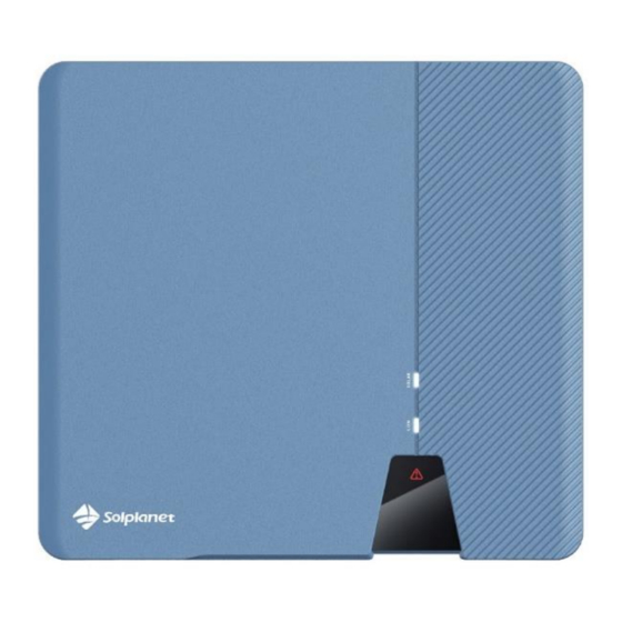
8 Operation The information provided here covers the LED indicators. 8.1 Overview of the panel The inverter is equipped with three LEDs indicators. Object Description Normal (White LED) Communication (White LED) Fault (Red LED) UM0026_ASW5000-10000-S-A_EN_V01_0622... -
Page 41: Leds
8.1.1 LEDs The inverter is equipped with two LED indicators “white” and “red” which provide information about the various operating states. LED A: The LED A is lit when the inverter is operating normally. The LED A is off The inverter is not feeding into the grid. -
Page 42: Disconnecting The Inverter From Voltage Sources
9 Disconnecting the Inverter from Voltage Sources Prior to performing any work on the inverter, disconnect it from all voltage sources as described in this section. Always adhere strictly to the prescribed sequence. Destruction of the measuring device due to overvoltage •... -
Page 43: Technical Data
10 Technical Data 10.1 DC input data ASW5000-S- ASW6000-S- ASW8000-S- ASW10000-S- Type Max. PV array 7500Wp 9000Wp 12000Wp 15000Wp power(STC) Max. input voltage 600V MPP voltage range 80V-550V Rated input voltage 360V Initial feeding-in 100V voltage Min. feed-in power Max. input current 16A/16A/16A per MPP input Isc PV(absolute... -
Page 44: Ac Output Data
10.2 AC output data ASW5000-S ASW6000-S ASW8000-S ASW10000-S Type Rated active power 5000W 6000W 8000W 10000W Rated apparent 5000VA 6000VA 8000VA 10000VA power Max. apparent 5000VA 6600VA 8800VA 10000VA power Nominal AC voltage/ 220V,230V/180V-295V range AC power frequency/ 50, 60/±5Hz range Rated power frequency/rated grid... -
Page 45: General Data
10.3 General data ASW5000-S-A/ 6000-S-A/ 8000-S-A / 10000-S- General data communication: ● / ● / ○ WIFI/Meter/RS485 Display Zero power output Via connecting Smart meter Dimensions 503x435x183 (W x H x D mm) 18.5Kg Weight convection Cooling concept < 39 dB(A)@1m Noise emission (typical) indoor &... -
Page 46: Safety Regulations
10.4 Safety regulations Protective devices ASW5000-S-A/ 6000-S-A/ 8000-S-A/ 10000-S-A ● DC isolator ● / ● PV iso / Grid monitoring DC reverse polarity ● / ● protection / AC short- circuit current capability Residual current ● monitoring(GFCI) function Earth Fault Alarm cloud based, visible(AU) Protection class (according to IEC... -
Page 47: Tools And Torque
10.5 Tools and torque Tools and torque required for installation and electrical connections. Tools, model Object Torque Torque screwdriver, T25 Screws for the cover 2.5Nm Screw for second protective grounding connection Torque screwdriver, T20 1.6Nm Screws connecting inverter and wall bracket Flat-head screwdriver, Sunclix DC connector blade with 3.5mm... -
Page 48: Power Reduction
10.6 Power reduction In order to ensure inverter operation under safe conditions, the device may automatically decrease power output. Power reduction depends on many operating parameters including ambient temperature and input voltage, grid voltage, grid frequency and power available from the PV modules. This device can decrease power output during certain periods of the day according to these parameters. -
Page 49: Troubleshooting
11 Troubleshooting When the PV system does not operate normally, we recommend the following solutions for quick troubleshooting. If an error occurs, the red LED will light up. There will have “Event Messages" display in the monitor tools. The corresponding corrective measures are as follows: Object Error Corrective measures... - Page 50 inverter. If this fault is still being shown, contact the service. • Make sure the grounding connection of the inverter is reliable. •Make a visual inspection of all PV cables and modules. If this fault is still shown, contact the service. •...
-
Page 51: Maintenance
• Disconnect the inverter from the utility grid and 1, 2,3, Permanent the PV array and reconnect it after LED turn off. If 4,5,6, Fault this fault is still being displayed, contact the service. Contact the service if you meet other problems not in the table. 12 Maintenance Normally, the inverter needs no maintenance or calibration. -
Page 52: Recycling And Disposal
The entire EU Declaration of Conformity can be found at www.solplanet.net. 15 Warranty The factory warranty card is enclosed with the package, please keep well the factory warranty card. -
Page 53: Contact
AISWEI Technology (Shanghai) Co., Ltd. Hotline: +86 400 801 9996 (Mainland) +886 809 089 212 (Taiwan) Service email: service.china@aiswei-tech.com Web: https://solplanet.net/contact-us/ Add.: Room 905B, 757 Mengzi Road, Huangpu District, Shanghai, China AISWEI Pty Ltd. Hotline: +61 390 988 673 Service email: service.au@aiswei-tech.com Add.: Level 40, 140 William Street, Melbourne VIC 3000, Australia... - Page 54 Rest of the world Service email: service.row@aiswei-tech.com UM0026_ASW5000-10000-S-A_EN_V01_0622...
- Page 55 UM0026_ASW5000-10000-S-A_EN_V01_0622...
Need help?
Do you have a question about the ASW S-A Series and is the answer not in the manual?
Questions and answers